EP0349911A2 - Micromanipulateur - Google Patents
Micromanipulateur Download PDFInfo
- Publication number
- EP0349911A2 EP0349911A2 EP89111893A EP89111893A EP0349911A2 EP 0349911 A2 EP0349911 A2 EP 0349911A2 EP 89111893 A EP89111893 A EP 89111893A EP 89111893 A EP89111893 A EP 89111893A EP 0349911 A2 EP0349911 A2 EP 0349911A2
- Authority
- EP
- European Patent Office
- Prior art keywords
- support
- movement
- micromanipulator
- movement elements
- elements
- Prior art date
- Legal status (The legal status is an assumption and is not a legal conclusion. Google has not performed a legal analysis and makes no representation as to the accuracy of the status listed.)
- Granted
Links
Images
Classifications
-
- G—PHYSICS
- G01—MEASURING; TESTING
- G01Q—SCANNING-PROBE TECHNIQUES OR APPARATUS; APPLICATIONS OF SCANNING-PROBE TECHNIQUES, e.g. SCANNING PROBE MICROSCOPY [SPM]
- G01Q10/00—Scanning or positioning arrangements, i.e. arrangements for actively controlling the movement or position of the probe
- G01Q10/04—Fine scanning or positioning
-
- B—PERFORMING OPERATIONS; TRANSPORTING
- B25—HAND TOOLS; PORTABLE POWER-DRIVEN TOOLS; MANIPULATORS
- B25J—MANIPULATORS; CHAMBERS PROVIDED WITH MANIPULATION DEVICES
- B25J7/00—Micromanipulators
-
- B—PERFORMING OPERATIONS; TRANSPORTING
- B82—NANOTECHNOLOGY
- B82Y—SPECIFIC USES OR APPLICATIONS OF NANOSTRUCTURES; MEASUREMENT OR ANALYSIS OF NANOSTRUCTURES; MANUFACTURE OR TREATMENT OF NANOSTRUCTURES
- B82Y35/00—Methods or apparatus for measurement or analysis of nanostructures
-
- G—PHYSICS
- G01—MEASURING; TESTING
- G01Q—SCANNING-PROBE TECHNIQUES OR APPARATUS; APPLICATIONS OF SCANNING-PROBE TECHNIQUES, e.g. SCANNING PROBE MICROSCOPY [SPM]
- G01Q60/00—Particular types of SPM [Scanning Probe Microscopy] or microscopes; Essential components thereof
- G01Q60/10—STM [Scanning Tunnelling Microscopy] or apparatus therefor, e.g. STM probes
- G01Q60/16—Probes, their manufacture, or their related instrumentation, e.g. holders
-
- H—ELECTRICITY
- H01—ELECTRIC ELEMENTS
- H01J—ELECTRIC DISCHARGE TUBES OR DISCHARGE LAMPS
- H01J37/00—Discharge tubes with provision for introducing objects or material to be exposed to the discharge, e.g. for the purpose of examination or processing thereof
- H01J37/02—Details
- H01J37/20—Means for supporting or positioning the object or the material; Means for adjusting diaphragms or lenses associated with the support
-
- H—ELECTRICITY
- H02—GENERATION; CONVERSION OR DISTRIBUTION OF ELECTRIC POWER
- H02N—ELECTRIC MACHINES NOT OTHERWISE PROVIDED FOR
- H02N2/00—Electric machines in general using piezoelectric effect, electrostriction or magnetostriction
- H02N2/02—Electric machines in general using piezoelectric effect, electrostriction or magnetostriction producing linear motion, e.g. actuators; Linear positioners ; Linear motors
- H02N2/021—Electric machines in general using piezoelectric effect, electrostriction or magnetostriction producing linear motion, e.g. actuators; Linear positioners ; Linear motors using intermittent driving, e.g. step motors, piezoleg motors
- H02N2/025—Inertial sliding motors
-
- H—ELECTRICITY
- H02—GENERATION; CONVERSION OR DISTRIBUTION OF ELECTRIC POWER
- H02N—ELECTRIC MACHINES NOT OTHERWISE PROVIDED FOR
- H02N2/00—Electric machines in general using piezoelectric effect, electrostriction or magnetostriction
- H02N2/02—Electric machines in general using piezoelectric effect, electrostriction or magnetostriction producing linear motion, e.g. actuators; Linear positioners ; Linear motors
- H02N2/04—Constructional details
- H02N2/043—Mechanical transmission means, e.g. for stroke amplification
- H02N2/046—Mechanical transmission means, e.g. for stroke amplification for conversion into rotary motion
-
- H—ELECTRICITY
- H02—GENERATION; CONVERSION OR DISTRIBUTION OF ELECTRIC POWER
- H02N—ELECTRIC MACHINES NOT OTHERWISE PROVIDED FOR
- H02N2/00—Electric machines in general using piezoelectric effect, electrostriction or magnetostriction
- H02N2/02—Electric machines in general using piezoelectric effect, electrostriction or magnetostriction producing linear motion, e.g. actuators; Linear positioners ; Linear motors
- H02N2/06—Drive circuits; Control arrangements or methods
- H02N2/065—Large signal circuits, e.g. final stages
- H02N2/067—Large signal circuits, e.g. final stages generating drive pulses
Definitions
- the invention relates to a micromanipulator for moving an object relative to a processing or analysis position so that at least a part of the object surface can be processed or analyzed.
- the micromanipulator has several movement elements which support the object or an object holder and which are provided with a support for the object or the object holder.
- the movement elements are piezoelectrically adjustable for executing micro movements.
- Micromanipulators of this type are known for executing movements in scanning tunnel microscopes (RTM).
- RTM scanning tunnel microscopes
- the RTM requires maximum precision for the movement of the object to be examined relative to the scanning needle (tunnel tip) of the RTM.
- DE-OS-36 10 540 describes a micromanipulator in which several movement elements made of piezoelectric material are used to support the object to be examined.
- the movement elements are designed in such a way that both translational and rotational movements and a tilting of the object are possible by means of micro movements.
- the described micromanipulator is set up for micro movements of the object, wherein macro movements are also possible in the addition of micro movements to be processed. Movements are perpendicular to the aforementioned object level can only be carried out to the extent that the deformation of the piezoelectric material that can be achieved by applying electrical voltages permits it.
- the object of the invention is to provide a micromanipulator with which macro movements can also be carried out in any direction with the movement elements provided for the micro movement.
- This object is achieved according to the invention in a micromanipulator of the type mentioned in claim 1 in that the object is mounted on at least one of the movement elements in such a way that micro and macro movements can also be carried out perpendicular to the processing or analysis plane of the object .
- This enables the distance between the processing and analysis level and the processing tool to be adjusted, for example the setting of the distance between the object surface to be processed or analyzed and the stylus of an RTM, even with a rough object surface, the roughness of which is not caused by micro-movements solely by deforming the piezoelectric material can be compensated, or after replacing and installing the stylus.
- the support of a movement element is particularly suitable for macro movement, claim 2.
- the support is preferably movably mounted in the movement element itself according to claim 3, wherein at the same time a guide of the support is provided on the movement element.
- the frictional forces must be such that they are used as a support of the object are sufficient and that, on the other hand, by applying voltage functions to the piezoelectric movement element, a sliding of the support in the socket in the axial direction can be achieved, claim 4.
- the piezoceramic design of the movement element is also perpendicular to the machining or analysis Layer can be used for both the micro movement and the macro movement of the object.
- At least one of the movement elements of the micromanipulator is attached to a section of the base plate that is macro-movable.
- the section is adjustable against the force of a spring which is attached to the base plate on the one hand and to the section on the other.
- two leaf springs are arranged one on top of the other, which can be spread apart. When the leaf springs are spread, the distance between the fastening points of the leaf springs on the base plate and section changes, so that the section is moved when the base plate is stationary. It is essential that the spreading of the leaf springs results in a parabolic dependency between the spreading path and the adjustment of the section, the adjustability increases with the spreading of the leaf springs.
- the leaf springs are therefore arranged on the section so that the setting sensitivity between the object and, for example, a stylus of an RTM is increased as the object and the stylus advance.
- a variant of the invention in which the piezoelectric control of the movement elements is also used for the macro movement relates to the patent Proverbs 8 to 10. Then the movement elements support the object or the object holder via a support plane that runs obliquely to the direction of support of the movement elements, the normal of which is at an angle to the direction of support of the movement elements. If the inclined support plane is moved by movement of the piezoelectric movement elements, the position of the object surface firmly connected to the inclined plane changes in the support direction of the movement elements.
- the size of the angle to be selected depends, on the one hand, on the performance of the piezoelectric movement elements with regard to their lateral deflectability at the support point, and on the other hand on the frictional forces which prevail at the support points of the movement elements on the surface of the support plane.
- the support plane is preferably polished.
- a movement of the support plane by means of the movement elements or a movement of the micromanipulator in the case of a stationary object takes place by applying electrical voltage profiles to the piezoceramic of the movement elements.
- the choice of the angle determines the amount of displacement of the object surface to be processed or analyzed perpendicular to the processing or analysis plane, for example perpendicular to the scanning needle of the RTM.
- the inclined support plane is preferably of helical design and is supported by the movement elements in the axial direction, so that when the support plane rotates, the processing or analysis plane shifts axially. It is advantageous to divide the helical support plane into several sections of the same design, each section being supported by one of the movement elements.
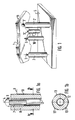
- Figure 1 of the drawing shows a micromanipulator for moving an object or object holder 1 by means of three movement elements 2, 2 ', 2 ⁇ supporting the object holder.
- the object holder lies on supports 3, 3 ', 3 ⁇ of the movement elements in a stable position.
- the cylindrical movement elements 2, 2 ', 2 ⁇ in the exemplary embodiment are attached to a base plate 5 with a vertical cylinder axis 4.
- the micromanipulator is used to move the object relative to a scanning needle 6, which in the exemplary embodiment is between the movement supply elements 2, 2 ', 2 ⁇ arranged on a moving element 10 and also attached to the base plate 5.
- the object 1 being displaceable to the scanning needle 6 of the RTM in the nano range.
- the arrangement of the scanning needle 6 on the moving element 10 on the base plate 5 between the moving elements 2, 2 ', 2 ⁇ is not mandatory.
- the scanning needle with the movement element 10 can also be attached to the base plate at another location. Because of the not inconsiderable temperature drift between the moving elements 2, 2 ', 2 ⁇ and the scanning needle 6 when processing or analyzing the object surface by means of RTM, the arrangement of moving elements and scanning needle on the same base plate is of great advantage.
- the pads 3 ', 3 ⁇ are rigidly connected to the associated movement elements 2', 2 ⁇ .
- the support 3 of the movement element 2 is arranged to be movable. As shown in FIG. 1 a, the support 3 is inserted in an axially extending manner in a bushing 7 within the moving element 2, the piezoelectric material 8 of which is designed as a tube. In the exemplary embodiment, the bushing 7 is embedded in the piezoelectric material 8.
- electrical conductors 9 are fed by a generator which is used to generate the desired control voltages for the required deformations of the piezoelectric material. The aforementioned generator is not shown in the drawing.
- the socket 7 and the support 3 are dimensioned such that there are frictional forces between their adjoining surfaces, which hold the support 3 immovably in the socket 7 when an object or object holder 1 is placed on it.
- Such control voltage pulses are applied to the piezoelectric material 8 that the piezoelectric material spontaneously axially stretches or shortens and thereby overcomes the static friction forces between the sleeve 7 and the pad 3, so that the pad due to its inertia within the moving element relative to the sleeve shifts. In this way, both upward and downward movements of the support in the moving element can be carried out.
- the position of the object 1 changes relative to the scanning needle 6.
- the object 1 is tilted about an axis 11, FIG. 1, the position of which remains the fixed supports 3 ', 3 ⁇ Movement elements 2 ', 2 ⁇ is specified.
- a movement between the scanning needle and the object surface to be processed or analyzed is also generated in the macro region.
- the movement elements 2, 2 ', 2 ⁇ in the exemplary embodiment are all of hollow cylindrical design, as shown in FIG. 1a for the movement element 2, in longitudinal section.
- FIG. 1b shows a cross section of the movement element along section line b / b according to FIG. 1a perpendicular to the cylinder axis 4. From the figures it can be seen that the piezoelectric material 8 is covered on its inside with an inner electrode 12, on its outer side with strip electrodes 13, 13 ', 13 ⁇ , which extend in the direction of the cylinder axis 4. If voltage profiles are applied to the electrodes, the length of the movement elements can be changed or bent. According to the invention, it is therefore only necessary to regulate these voltage profiles in order to move the object or object holder in any direction, macro movements being achieved by stepwise addition of micro movements also perpendicular to the processing or analysis plane of the object.
- the elements required for the vertical movement of the object namely movable support 3 and bushing 7 embedded in piezoelectric material 8 are integrated in the movement element.
- these elements can also be arranged separately and connected to the movement element.
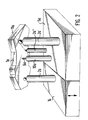
- FIG. 2 shows a micromanipulator in which one of the movement elements 2a, 2a ', 2a ⁇ , in the exemplary embodiment the movement element 2a, is arranged on a section 14 which is movable relative to the base plate 5a.
- the section 14 is moved, in the exemplary embodiment a movement of the section perpendicular to the surface of the base plate 5a is provided, the object holder 1a of the micromanipulator according to FIG. 2 - analogous to the object 1 according to FIG. 1 - by one tilted through the bases of the movement elements 2a ', 2a Obj on the object holder 1a axis 11a.
- the movement elements 2a, 2a ', 2a ⁇ are designed in the same way as movement elements 2, 2', 2 ⁇ according to Figure 1, 1a and 1b.
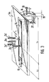
- a section 14a fastened between leaf springs on the base plate 5a is shown in FIG. 3. It is fastened at one end to the base plate 5a with a leaf spring 15, and at the other end via two leaf springs 16, 17 which are arranged one on top of the other in the relaxed state the base plate 5a connected.
- the leaf springs 16, 17 can be spread by means of a clamping screw 18.
- the displacement of the section 14 increases depending on the spreading distance 19 between the leaf springs 16, 17 parabolically with increasing spread.
- the leaf springs 16, 17 are arranged between the base plate 5a and section 14 in such a way that the sensitivity of the section 14 increases when the tensioning screw 18 is adjusted as the object and the scanning needle advance.
- the leaf springs 16, 17 are arranged in the exemplary embodiment according to FIG.
- the reduction ratio between the spreading of the leaf springs 16, 17 generated displacement of the section and distance between the object surface and the stylus is variable by choice of the lever ratios L1: L2, L3: L4 and by the pitch of the screw thread of the clamping screw 18 within wide limits.
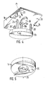
- Figure 4 shows a micromanipulator, the movement elements 2b, 2b ', 2b ⁇ of which support an inclined support plane 21.
- the support plane 21 is part of the object holder 1b with which the object 1b' to be processed or examined is firmly connected.
- the micromanipulator shown in FIG. 4 also serves to move an object holder of an RTM, the scanning needle 6b of which is arranged with its moving element 10b together with the moving elements 2b, 2b ', 2bens on one and the same base plate 5b.
- the movement elements 2b, 2b ', 2b ⁇ which are likewise cylindrical in the embodiment according to FIG. 4, are perpendicular to the base plate 5b, their cylinder axes 4b are arranged parallel to the support direction 22 of the movement elements.
- Support direction 22 and normal 23 of the support plane 21 run at an angle to one another. The angle formed between the support direction 22 and the normal 23 is chosen so that even when the slide 1b is moved by means of the piezo-electrically excitable movement elements, there is sufficient adhesion between the supports 3b, 3b ', 3illages of the movement elements and the surface of the inclined support plane given is.
- the slide 1b must not slide on the movement elements.
- the performance of the piezoelectric movement elements for moving the slide must be taken into account when choosing the angle. The angle can be increased with increasing performance.
- the inclined support plane can be shifted and thus the distance between the object surface and the tip of the scanning needle can be changed.
- the distance between the tip of the needle and the object surface remains constant if the inclined plane is shifted parallel to a horizontal edge.
- FIG. 5 shows an object holder 1c with a helically extending support plane 25.
- the support plane 25 rotates by means of movement elements not shown in FIG. 5, the object 1c ′ arranged centrally in the object holder 1c is moved in the direction of the screw axis 26.
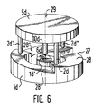
- FIG. 6 shows a micromanipulator equipped with a likewise helical support plane.
- the object holder 1d of this micromanipulator has a support plane 27, which consists of several sections 28, 28 ′, 28 ⁇ in the exemplary embodiment consisting of three helically running sections. Each of the sections has the same design in the exemplary embodiment, in particular the screw surfaces each have the same pitch, in the exemplary embodiment a pitch of 0.3 mm per section.
- the sections 28, 28 ', 28 ⁇ are each supported by one of the movement elements 2d, 2d', 2d ⁇ .
- the object holder 1d is arranged in a stationary manner and the micromanipulator is freely movable on the support plane.
- the micromanipulator moves in the direction of a central axis 29 when the movement elements rotate the micromanipulator about the central axis via the support plane.
- the object to be processed or analyzed 1d ' is arranged centrally.
- the object surface runs parallel to Base plate 5d of the micromanipulator, on which, in the same way as in all of the previous exemplary embodiments, a scanning needle 6d of an RTM is fastened with its moving element 10d and the moving elements 2d, 2d ', 2d ⁇ .
- the movement elements 10 with the scanning needles are also piezoelectrically movable in the exemplary embodiments.
Landscapes
- Engineering & Computer Science (AREA)
- Chemical & Material Sciences (AREA)
- Health & Medical Sciences (AREA)
- General Health & Medical Sciences (AREA)
- General Physics & Mathematics (AREA)
- Nuclear Medicine, Radiotherapy & Molecular Imaging (AREA)
- Radiology & Medical Imaging (AREA)
- Physics & Mathematics (AREA)
- Analytical Chemistry (AREA)
- Mechanical Engineering (AREA)
- Robotics (AREA)
- Nanotechnology (AREA)
- Crystallography & Structural Chemistry (AREA)
- Manipulator (AREA)
- Microscoopes, Condenser (AREA)
- Micromachines (AREA)
Applications Claiming Priority (2)
| Application Number | Priority Date | Filing Date | Title |
|---|---|---|---|
| DE3822504 | 1988-07-03 | ||
| DE3822504A DE3822504A1 (de) | 1988-07-03 | 1988-07-03 | Mikromanipulator |
Publications (3)
| Publication Number | Publication Date |
|---|---|
| EP0349911A2 true EP0349911A2 (fr) | 1990-01-10 |
| EP0349911A3 EP0349911A3 (fr) | 1991-07-17 |
| EP0349911B1 EP0349911B1 (fr) | 1995-09-20 |
Family
ID=6357870
Family Applications (1)
| Application Number | Title | Priority Date | Filing Date |
|---|---|---|---|
| EP89111893A Expired - Lifetime EP0349911B1 (fr) | 1988-07-03 | 1989-06-30 | Micromanipulateur |
Country Status (7)
| Country | Link |
|---|---|
| US (1) | US5325010A (fr) |
| EP (1) | EP0349911B1 (fr) |
| JP (1) | JP2802317B2 (fr) |
| AT (1) | ATE128270T1 (fr) |
| DE (4) | DE3844659A1 (fr) |
| ES (1) | ES2080734T3 (fr) |
| GR (1) | GR3018451T3 (fr) |
Cited By (5)
| Publication number | Priority date | Publication date | Assignee | Title |
|---|---|---|---|---|
| EP0790480A1 (fr) * | 1996-02-09 | 1997-08-20 | Lucent Technologies Inc. | Positionneur basculant pour appareil de micropositionnement |
| US6198299B1 (en) | 1998-08-27 | 2001-03-06 | The Micromanipulator Company, Inc. | High Resolution analytical probe station |
| US6744268B2 (en) | 1998-08-27 | 2004-06-01 | The Micromanipulator Company, Inc. | High resolution analytical probe station |
| WO2005101088A3 (fr) * | 2004-04-12 | 2006-06-08 | Applied Scient Instrumentation | Ensemble etage et procede pour microscope otique comprenant un etage a axe z et un actionneur piezo-electrique pour translation rectiligne de l'etage z |
| US7584653B2 (en) | 2003-08-11 | 2009-09-08 | Veeco Instruments, Inc. | System for wide frequency dynamic nanomechanical analysis |
Families Citing this family (44)
| Publication number | Priority date | Publication date | Assignee | Title |
|---|---|---|---|---|
| DE3918249C1 (fr) * | 1989-06-05 | 1990-09-13 | Forschungszentrum Juelich Gmbh, 5170 Juelich, De | |
| US5155361A (en) | 1991-07-26 | 1992-10-13 | The Arizona Board Of Regents, A Body Corporate Acting For And On Behalf Of Arizona State University | Potentiostatic preparation of molecular adsorbates for scanning probe microscopy |
| JP2905643B2 (ja) * | 1992-05-29 | 1999-06-14 | 住友重機械工業株式会社 | 圧電リニアアクチュエータ |
| US5568004A (en) * | 1992-09-07 | 1996-10-22 | Kleindiek; Stephan | Electromechanical positioning device |
| US5616980A (en) * | 1993-07-09 | 1997-04-01 | Nanomotion Ltd. | Ceramic motor |
| IL106296A0 (en) * | 1993-07-09 | 1993-12-28 | Nanomotion Ltd | Ceramic motor |
| US5682076A (en) * | 1993-08-03 | 1997-10-28 | Nanomotion Ltd. | Ceramic disc-drive actuator |
| US5440920A (en) | 1994-02-03 | 1995-08-15 | Molecular Imaging Systems | Scanning force microscope with beam tracking lens |
| US5515719A (en) | 1994-05-19 | 1996-05-14 | Molecular Imaging Corporation | Controlled force microscope for operation in liquids |
| US5866805A (en) | 1994-05-19 | 1999-02-02 | Molecular Imaging Corporation Arizona Board Of Regents | Cantilevers for a magnetically driven atomic force microscope |
| US5513518A (en) | 1994-05-19 | 1996-05-07 | Molecular Imaging Corporation | Magnetic modulation of force sensor for AC detection in an atomic force microscope |
| US5753814A (en) | 1994-05-19 | 1998-05-19 | Molecular Imaging Corporation | Magnetically-oscillated probe microscope for operation in liquids |
| US5629577A (en) | 1994-07-15 | 1997-05-13 | Micro Medical Devices | Miniature linear motion actuator |
| JPH0837784A (ja) * | 1994-07-25 | 1996-02-06 | Nikon Corp | 移動装置及び移動装置の制御方法 |
| US5675154A (en) * | 1995-02-10 | 1997-10-07 | Molecular Imaging Corporation | Scanning probe microscope |
| US5621210A (en) * | 1995-02-10 | 1997-04-15 | Molecular Imaging Corporation | Microscope for force and tunneling microscopy in liquids |
| US5750989A (en) * | 1995-02-10 | 1998-05-12 | Molecular Imaging Corporation | Scanning probe microscope for use in fluids |
| US5569918A (en) * | 1995-03-17 | 1996-10-29 | Rhk Technology, Inc. | Probe holder and probe mounting method for a scanning probe microscope |
| US5668432A (en) * | 1995-03-24 | 1997-09-16 | Nippondenso Co., Ltd. | Articulation device |
| US5821545A (en) * | 1995-11-07 | 1998-10-13 | Molecular Imaging Corporation | Heated stage for a scanning probe microscope |
| US5654546A (en) * | 1995-11-07 | 1997-08-05 | Molecular Imaging Corporation | Variable temperature scanning probe microscope based on a peltier device |
| WO1997036365A1 (fr) * | 1996-03-26 | 1997-10-02 | Stefan Johansson | Moteur actionneur et son procede de fabrication |
| RU2149752C1 (ru) * | 1998-07-02 | 2000-05-27 | Государственное унитарное предприятие "Научно-производственное объединение конверсионного приборостроения" | Привод микроманипулятора |
| DE19833904C2 (de) * | 1998-07-22 | 2002-07-18 | Hahn Meitner Inst Berlin Gmbh | Verstelleinrichtung für die Positionierung eines Probentisches |
| DE19833905C2 (de) * | 1998-07-22 | 2002-05-08 | Hahn Meitner Inst Berlin Gmbh | Piezoelektrische Verstelleinrichtung für die Positonierung eines Probentisches |
| DE19847995A1 (de) * | 1998-10-17 | 2000-04-20 | Zeiss Carl Jena Gmbh | Anordnung zum Positionieren eines Objektes |
| US6181097B1 (en) * | 1999-02-11 | 2001-01-30 | Institute Of Materials Research And Engineering | High precision three-dimensional alignment system for lithography, fabrication and inspection |
| DE19935570C2 (de) * | 1999-07-30 | 2001-07-05 | Forschungszentrum Juelich Gmbh | Mikromanipulator |
| US6742380B2 (en) * | 2000-07-28 | 2004-06-01 | Seagate Technology Llc | Technique for measuring small distances between, and for measuring the flatness of, electrically conductive surfaces |
| US6661575B1 (en) | 2000-10-31 | 2003-12-09 | Sergey A. Yakovenko | Methods and apparata for micromanipulation of micro-and nanoparticles |
| DE10156870A1 (de) * | 2000-11-22 | 2002-07-11 | Univ Ilmenau Tech | Anordnung und Verfahren zur Erzeugung variabler Kennlinien von Antrieben |
| SE520097C2 (sv) * | 2000-12-05 | 2003-05-27 | Nanofactory Instruments Ab | Mikropositioneringsanordning |
| US6848328B2 (en) | 2001-03-09 | 2005-02-01 | Klocke Nanotechnik | Positioning unit and positioning apparatus with at least two positioning units |
| US20040090418A1 (en) * | 2002-11-12 | 2004-05-13 | Bio-Rad Laboratories, Inc., A Corporation Of The State Of Delaware | Joystick with axial disengagement switch |
| FR2850217A1 (fr) * | 2003-01-17 | 2004-07-23 | Cedrat Technologies | Actionneur piezoactif a deplacement amplifie amorti |
| DE102004049371B4 (de) * | 2004-10-09 | 2015-05-21 | Forschungszentrum Jülich GmbH | Nanomanipulator zum Analysieren oder Bearbeiten von Objekten |
| DE102005054551B3 (de) * | 2005-11-14 | 2006-12-28 | Carl Von Ossietzky Universität Oldenburg | Vorrichtung zum Verlagern von Endeffektoren an Mess- oder Handhabungseinrichtungen sowie Verfahren zur Bestimmung der Kontaktkraft oder der Position eines Endeffektors |
| US8059346B2 (en) | 2007-03-19 | 2011-11-15 | New Scale Technologies | Linear drive systems and methods thereof |
| FI20116111A7 (fi) * | 2011-11-10 | 2013-05-11 | Sensapex Oy | Mikromanipulaattorijärjestely |
| WO2013190783A1 (fr) * | 2012-06-18 | 2013-12-27 | 株式会社ニコン | Unité d'actionneur à vibration, appareil à étages, appareil optique et appareil à étages |
| JP6501388B2 (ja) * | 2014-11-20 | 2019-04-17 | 株式会社ホロン | 移動・傾斜機構 |
| DE102016202582A1 (de) * | 2016-02-19 | 2017-08-24 | Carl Zeiss Microscopy Gmbh | Verstelleinrichtung einer Probenhalterung, Mikroskop mit Verstelleinrichtung und Verfahren |
| CN110191784B (zh) * | 2016-09-30 | 2023-10-20 | 3Sae技术有限公司 | 多轴相对定位台 |
| CN111208320B (zh) * | 2020-03-09 | 2021-06-08 | 中国科学院物理研究所 | 扫描隧道显微镜及其样品架 |
Family Cites Families (10)
| Publication number | Priority date | Publication date | Assignee | Title |
|---|---|---|---|---|
| JPS5315060A (en) * | 1976-07-28 | 1978-02-10 | Hitachi Ltd | Inching device |
| US4195243A (en) * | 1978-11-06 | 1980-03-25 | Sperry Corporation | Piezoelectric wafer mover |
| CH643397A5 (de) * | 1979-09-20 | 1984-05-30 | Ibm | Raster-tunnelmikroskop. |
| GB2102691B (en) * | 1981-08-05 | 1985-01-09 | Cresta Tech | Rotary filter |
| JPH0614789B2 (ja) * | 1984-06-25 | 1994-02-23 | 株式会社東芝 | テーブル微動方法およびこの方法を用いた微動装置 |
| DE8531859U1 (de) * | 1985-11-11 | 1987-03-12 | Feinmetall Gmbh, 7033 Herrenberg | Mikro-Manipulator |
| DE3610540A1 (de) * | 1986-03-27 | 1987-10-01 | Kernforschungsanlage Juelich | Bewegungseinrichtung zur mikrobewegung von objekten |
| EP0252174B1 (fr) * | 1986-07-08 | 1991-01-02 | International Business Machines Corporation | Dispositif de réglage approximatif |
| EP0252745A3 (fr) * | 1986-07-11 | 1990-01-24 | AGENCY OF INDUSTRIAL SCIENCE & TECHNOLOGY MINISTRY OF INTERNATIONAL TRADE & INDUSTRY | Dispositif de commande de déplacement relatif |
| DE3632964A1 (de) * | 1986-09-27 | 1988-04-07 | Physik Instr Pi Gmbh & Co Prod | Piezoelektrisches stellglied |
-
1988
- 1988-07-03 DE DE3844659A patent/DE3844659A1/de active Granted
- 1988-07-03 DE DE3822504A patent/DE3822504A1/de active Granted
- 1988-07-03 DE DE3844821A patent/DE3844821C2/de not_active Expired - Lifetime
-
1989
- 1989-06-28 JP JP1164086A patent/JP2802317B2/ja not_active Expired - Lifetime
- 1989-06-30 AT AT89111893T patent/ATE128270T1/de not_active IP Right Cessation
- 1989-06-30 ES ES89111893T patent/ES2080734T3/es not_active Expired - Lifetime
- 1989-06-30 EP EP89111893A patent/EP0349911B1/fr not_active Expired - Lifetime
- 1989-06-30 DE DE58909442T patent/DE58909442D1/de not_active Expired - Lifetime
-
1993
- 1993-08-18 US US08/108,400 patent/US5325010A/en not_active Expired - Lifetime
-
1995
- 1995-12-19 GR GR950403583T patent/GR3018451T3/el unknown
Cited By (8)
| Publication number | Priority date | Publication date | Assignee | Title |
|---|---|---|---|---|
| EP0790480A1 (fr) * | 1996-02-09 | 1997-08-20 | Lucent Technologies Inc. | Positionneur basculant pour appareil de micropositionnement |
| US6198299B1 (en) | 1998-08-27 | 2001-03-06 | The Micromanipulator Company, Inc. | High Resolution analytical probe station |
| US6744268B2 (en) | 1998-08-27 | 2004-06-01 | The Micromanipulator Company, Inc. | High resolution analytical probe station |
| US6838895B2 (en) | 1998-08-27 | 2005-01-04 | The Micromanipulator Company, Inc. | High resolution analytical probe station |
| US7180317B2 (en) | 1998-08-27 | 2007-02-20 | The Micromanipulator Co., Inc. | High resolution analytical probe station |
| US7584653B2 (en) | 2003-08-11 | 2009-09-08 | Veeco Instruments, Inc. | System for wide frequency dynamic nanomechanical analysis |
| WO2005101088A3 (fr) * | 2004-04-12 | 2006-06-08 | Applied Scient Instrumentation | Ensemble etage et procede pour microscope otique comprenant un etage a axe z et un actionneur piezo-electrique pour translation rectiligne de l'etage z |
| US7180662B2 (en) * | 2004-04-12 | 2007-02-20 | Applied Scientific Instrumentation Inc. | Stage assembly and method for optical microscope including Z-axis stage and piezoelectric actuator for rectilinear translation of Z stage |
Also Published As
| Publication number | Publication date |
|---|---|
| DE58909442D1 (de) | 1995-10-26 |
| JP2802317B2 (ja) | 1998-09-24 |
| ES2080734T3 (es) | 1996-02-16 |
| DE3844821C2 (en) | 1993-07-22 |
| JPH0266841A (ja) | 1990-03-06 |
| DE3822504C2 (fr) | 1992-10-01 |
| EP0349911B1 (fr) | 1995-09-20 |
| GR3018451T3 (en) | 1996-03-31 |
| US5325010A (en) | 1994-06-28 |
| EP0349911A3 (fr) | 1991-07-17 |
| ATE128270T1 (de) | 1995-10-15 |
| DE3822504A1 (de) | 1990-01-04 |
| DE3844659A1 (de) | 1990-11-29 |
Similar Documents
| Publication | Publication Date | Title |
|---|---|---|
| EP0349911B1 (fr) | Micromanipulateur | |
| DE4023311C2 (fr) | ||
| DE3933296C2 (de) | Mikromanipulator | |
| EP2409164B1 (fr) | Dispositif et méthode de positionnement electromecanique | |
| DE9421715U1 (de) | Elektromechanische Positioniereinheit | |
| DE2733924B2 (de) | In zwei Richtungen wirksame Feinjustiereinrichtung | |
| DE19644550C1 (de) | Piezoelektrischer oder elektrostriktiver Trägheitsantrieb zum Verschieben oder Positionieren von insbesondere schweren Objekten | |
| DE20023361U1 (de) | Elektromechanische Antriebsvorrichtung mit Piezoelement | |
| DE69005689T2 (de) | Mechanische Objektplatte, insbesondere für ein Tunneleffektmikroskop. | |
| AT402092B (de) | Linearführung | |
| DE102015107245B4 (de) | 1einstellvorrichtung für eine beleuchtungskomponente eines mikroskops, eine mikroskop-beleuchtungsvorrichtung und ein mikroskop | |
| DE3519386A1 (de) | Vorrichtung zum ausrichten und positionieren einer krafteinheit | |
| DE3820085C1 (en) | Microtome, especially ultramicrotome | |
| WO1988001434A1 (fr) | Porte-echantillon deplaçable pour un microscope a rayonnement corpusculaire | |
| EP0861388B1 (fr) | Entrainement d'arbre | |
| DE102012221892B4 (de) | Antriebsvorrichtung und -verfahren zur linearen oder rotatorischen Positionierung | |
| DE4410248C1 (de) | Piezoelektrische Antriebsvorrichtung | |
| DE102004013549A1 (de) | Vorrichtung zum Erodieren konischer Bohrungen | |
| DE19744311C1 (de) | Verstelleinrichtung | |
| DE2346758A1 (de) | Aufnahmeobjektiv fuer kameras | |
| EP1650590B1 (fr) | Dispositif d'ajustement destiné au positionnement très précis d'un objet | |
| DE102013201604B4 (de) | Kippvorrichtung und Verfahren zum Kippen | |
| DE102018001131A1 (de) | Vorrichtung zum Abstützen eines zu bearbeitenden Werkstücks | |
| WO2008092504A1 (fr) | Procédé de positionnement et/ou de fixation de pièces à usiner et dispositif correspondant | |
| DE2738240C2 (de) | Lageranordnung für den Schwingstab von Mikrotomen, insbesondere Ultramikrotomen |
Legal Events
| Date | Code | Title | Description |
|---|---|---|---|
| PUAI | Public reference made under article 153(3) epc to a published international application that has entered the european phase |
Free format text: ORIGINAL CODE: 0009012 |
|
| AK | Designated contracting states |
Kind code of ref document: A2 Designated state(s): AT BE CH DE ES FR GB GR IT LI LU NL SE |
|
| RAP3 | Party data changed (applicant data changed or rights of an application transferred) |
Owner name: FORSCHUNGSZENTRUM JUELICH GMBH |
|
| 17P | Request for examination filed |
Effective date: 19901221 |
|
| PUAL | Search report despatched |
Free format text: ORIGINAL CODE: 0009013 |
|
| AK | Designated contracting states |
Kind code of ref document: A3 Designated state(s): AT BE CH DE ES FR GB GR IT LI LU NL SE |
|
| 17Q | First examination report despatched |
Effective date: 19940217 |
|
| GRAA | (expected) grant |
Free format text: ORIGINAL CODE: 0009210 |
|
| AK | Designated contracting states |
Kind code of ref document: B1 Designated state(s): AT BE CH DE ES FR GB GR IT LI LU NL SE |
|
| REF | Corresponds to: |
Ref document number: 128270 Country of ref document: AT Date of ref document: 19951015 Kind code of ref document: T |
|
| REF | Corresponds to: |
Ref document number: 58909442 Country of ref document: DE Date of ref document: 19951026 |
|
| ITF | It: translation for a ep patent filed | ||
| GBT | Gb: translation of ep patent filed (gb section 77(6)(a)/1977) |
Effective date: 19951120 |
|
| ET | Fr: translation filed | ||
| REG | Reference to a national code |
Ref country code: ES Ref legal event code: FG2A Ref document number: 2080734 Country of ref document: ES Kind code of ref document: T3 |
|
| REG | Reference to a national code |
Ref country code: GR Ref legal event code: FG4A Free format text: 3018451 |
|
| PLBE | No opposition filed within time limit |
Free format text: ORIGINAL CODE: 0009261 |
|
| STAA | Information on the status of an ep patent application or granted ep patent |
Free format text: STATUS: NO OPPOSITION FILED WITHIN TIME LIMIT |
|
| 26N | No opposition filed | ||
| REG | Reference to a national code |
Ref country code: GB Ref legal event code: IF02 |
|
| PGFP | Annual fee paid to national office [announced via postgrant information from national office to epo] |
Ref country code: LU Payment date: 20080627 Year of fee payment: 20 Ref country code: CH Payment date: 20080624 Year of fee payment: 20 Ref country code: ES Payment date: 20080625 Year of fee payment: 20 |
|
| PGFP | Annual fee paid to national office [announced via postgrant information from national office to epo] |
Ref country code: AT Payment date: 20080620 Year of fee payment: 20 |
|
| PGFP | Annual fee paid to national office [announced via postgrant information from national office to epo] |
Ref country code: BE Payment date: 20080623 Year of fee payment: 20 |
|
| PGFP | Annual fee paid to national office [announced via postgrant information from national office to epo] |
Ref country code: SE Payment date: 20080624 Year of fee payment: 20 Ref country code: DE Payment date: 20080606 Year of fee payment: 20 Ref country code: NL Payment date: 20080618 Year of fee payment: 20 |
|
| PGFP | Annual fee paid to national office [announced via postgrant information from national office to epo] |
Ref country code: IT Payment date: 20080627 Year of fee payment: 20 Ref country code: FR Payment date: 20080618 Year of fee payment: 20 |
|
| PGFP | Annual fee paid to national office [announced via postgrant information from national office to epo] |
Ref country code: GB Payment date: 20080624 Year of fee payment: 20 |
|
| PGFP | Annual fee paid to national office [announced via postgrant information from national office to epo] |
Ref country code: GR Payment date: 20080626 Year of fee payment: 20 |
|
| BE20 | Be: patent expired |
Owner name: FORSCHUNGSZENTRUM *JULICH G.M.B.H. Effective date: 20090630 |
|
| REG | Reference to a national code |
Ref country code: CH Ref legal event code: PL |
|
| REG | Reference to a national code |
Ref country code: GB Ref legal event code: PE20 Expiry date: 20090629 |
|
| PG25 | Lapsed in a contracting state [announced via postgrant information from national office to epo] |
Ref country code: NL Free format text: LAPSE BECAUSE OF EXPIRATION OF PROTECTION Effective date: 20090630 |
|
| REG | Reference to a national code |
Ref country code: ES Ref legal event code: FD2A Effective date: 20090701 |
|
| NLV7 | Nl: ceased due to reaching the maximum lifetime of a patent |
Effective date: 20090630 |
|
| EUG | Se: european patent has lapsed | ||
| PG25 | Lapsed in a contracting state [announced via postgrant information from national office to epo] |
Ref country code: ES Free format text: LAPSE BECAUSE OF EXPIRATION OF PROTECTION Effective date: 20090701 |
|
| PG25 | Lapsed in a contracting state [announced via postgrant information from national office to epo] |
Ref country code: GB Free format text: LAPSE BECAUSE OF EXPIRATION OF PROTECTION Effective date: 20090629 |