EP0354517A2 - Mittelkanal-Kontrollschaltung - Google Patents
Mittelkanal-Kontrollschaltung Download PDFInfo
- Publication number
- EP0354517A2 EP0354517A2 EP89114569A EP89114569A EP0354517A2 EP 0354517 A2 EP0354517 A2 EP 0354517A2 EP 89114569 A EP89114569 A EP 89114569A EP 89114569 A EP89114569 A EP 89114569A EP 0354517 A2 EP0354517 A2 EP 0354517A2
- Authority
- EP
- European Patent Office
- Prior art keywords
- center
- signal
- input signal
- control circuit
- mode control
- Prior art date
- Legal status (The legal status is an assumption and is not a legal conclusion. Google has not performed a legal analysis and makes no representation as to the accuracy of the status listed.)
- Granted
Links
Images

Classifications
-
- H—ELECTRICITY
- H04—ELECTRIC COMMUNICATION TECHNIQUE
- H04S—STEREOPHONIC SYSTEMS
- H04S5/00—Pseudo-stereo systems, e.g. in which additional channel signals are derived from monophonic signals by means of phase shifting, time delay or reverberation
-
- H—ELECTRICITY
- H04—ELECTRIC COMMUNICATION TECHNIQUE
- H04S—STEREOPHONIC SYSTEMS
- H04S3/00—Systems employing more than two channels, e.g. quadraphonic
Definitions
- the present invention relates to a center mode control circuit, and more specifically, to a center mode control circuit employed, for example, in a Dolby Pro Logic Surround Decoder, and suitable for an IC (Integrated Circuit).
- a structure such as shown in Fig. 2 enables a signal processing of enhancement of direction to clarify surround localization of sound, so that acoustics having presence can be provided to listeners.
- the system is effective when applied to an audio signal processing of a large-sized television, so that it can produce the same effect on audience as that is obtained in seeing a picture at a theater.
- the center mode control circuit is disposed in order to switch for a normal mode, a phantom mode and a wide mode.
- a normal mode only low frequency component of the center output signal C is added to the left and the right stereo output signals L and R.
- a phantom mode full range of the center output signal C is added to the left and the right stereo output signals L and R.
- a wide mode nothing is added, and the left and the right stereo output signals L and R are generated as they are.
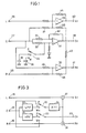
- Fig. 3 is a circuit diagram showing an example of the conventional center mode control circuit, wherein left and right stereo input signals L and R applied to left and right input terminals 15 and 16 are directly applied to first and second adder circuit 17 and 18, respectively.
- a center input signal applied to a center input terminal 19 is passed through a low pass filter 20 or a high pass filter 21, or directly transferred to terminals of first and second switches 22 and 23.
- the signal passed through the first switch 22 is applied to an attenuation circuit 24, wherein it is attenuated by 3 dB to be applied to the first and the second adder circuits 17 and 18, while the signal passed through the second switch 23 is provided to a center output terminal 25 as a center output signal C0.
- the center input signal C is applied to the first and the second adder circuits 17 and 18 through the attenuation circuit 24.
- the left stereo output signal L0 becomes L+C
- the right stereo signal R0 becomes R+C.
- the left and the right stereo input signals L and R become the left and right stereo output signals L0 and R0, respectively, and the center output signal C0 becomes equal to the center input signal C.
- circuit of Fig. 3 enables an accurate center mode controlling.
- the circuit of Fig. 3 had a problem in that it required the low pass filter 20 and the high pass filter 21, so that adjustment of characteristics of these filters was difficult.
- the low pass filter 20, the high pass filter 21 and the first and the second switches 22 and 23 should be externally attached to the IC, thereby increasing the number of pins for external attachment, so that it was not suitable for an integrated circuit.
- An object of the present invention is to provide a center mode control circuit in which adjustment of filter characteristics is not necessary.
- Another object of the present invention is to provide a center mode control circuit having the fewer number of parts to be externally attached, and suitable for an integrated circuit.
- a center mode control circuit in short, comprises an amplifying portion for amplifying a center input signal, a switch connected to an input of the amplifying portion, and capacitors to be selected by the switch and having different characteristics to each other, wherein a normal mode, a phantom mode and a wide mode can be switched by controlling the switch.
- a mode can be selected only by controlling the switch connected to the input end of the amplifying portion.
- the switch is set to the normal position, a capacitor for grounding only high frequency component of the center input signal is connected to the input end of the amplifying portion, so that only low frequency component of the center input signal can be added to the left and the right stereo input signals.
- the switch is set to the phantom position, the input end of the amplifying portion becomes open, so that full range of the center input signal can be added to the left and the right stereo input signals.
- the switch is set to the wide position, a capacitor for grounding full range of the center input signal is connected to the input end of the amplifying portion, so that no adding is performed. Therefore, according to the present invention, switching of the switch connected to the input end of the amplifying portion enables selection of three modes.
- Fig. 1 is a circuit diagram showing one embodiment of the present invention, wherein 26 denotes a first input terminal to which a left stereo input signal L is applied, 27 denotes a second input terminal to which a center input terminal C is applied, 28 denotes a third input terminal to which a right stereo input signal R is applied, 29 denotes a first adding and amplifying circuit for adding the left stereo input signal L and the center input signal C, 30 denotes a second adding and amplifying circuit for adding the right stereo input signal R and the center input signal C, 31 denotes an inversion amplifier circuit having its positive and negative input terminals connected through a resister 33 and 32, respectively, to the second input terminal 27, 34 denotes a switch connected to the positive input terminal of the inversion amplifier circuit 31, 35 denotes a first capacitor connected to a second fixed terminal of the switch 34, for grounding high frequency component of the center input signal, 36 denotes a second capacitor connected to a third fixed terminal of the switch 34, for grounding full range of the center input signal
- the center input signal high frequency component of the opposite polarity is added to the center input signal by means of addition resistors 37 and 38, so that consequently, a center input signal low frequency component C L is applied to the first adding and amplifying circuit 29 to be added to the left stereo input signal L.
- the center input signal is simultaneously applied to the positive and the negative input terminals of the inversion amplifier circuit 31, so that no output signal is generated at the output terminal of the inversion amplifier circuit 31. Therefore, the center input signal C is applied to the first and the second adding and amplifying circuit 29 and 30 through the addition resistances 37 and 38, 42 and 43, respectively, to be added to the left and the right stereo input signals L and R.
- the center input signal is added to the left and the right stereo input signals, so that it becomes a suitable mode especially for a system without a center speaker.
- the center input signal is applied only to the negative input terminal of the inversion amplifier circuit 31, so that an inverted signal of the center input signal is obtained at the output terminal of the inversion amplifier circuit 31.
- the inverted signal is added to the center input signal by means of the addition resistors 37, 38, 42 and 43 to be cancelled. Therefore, only left and right stereo input signals L and R are respectively applied to the first and the second adding and amplifying circuits 29 and 30, and the left and the right stereo input signals L and R are generated respectively at the first and the third output terminals 40 and 41 as the output signals L0 and R0, while the center input signal C is generated as the output signal C0 at the second output terminal 39.
- the left and the right stereo input signals L and R and the center input signal C are applied respectively to a speaker as the left and the right stereo output signals L0 and R0 and the center output signal C0, thereby forming a normal surround system.
- a level of the center input signal C is decreased by 3 dB to be added to the left and the right stereo input signals L and R in order not to increase sound volume in adding. This can be performed by adequately setting ratio of feedback resistors 44 and 45 of the first and the second adding and amplifying circuits 29 and 30, and the addition resistors 37 and 38, 42 and 43.
- a center mode control circuit in processing a center input signal to generate a signal to be added to left and right stereo input signals, can be comprised of only high pass inversion amplifier circuits, so that setting of characteristics is facilitated, and thereby providing a center mode control circuit with small dispersion.
- the center mode control circuit according to the present invention is suitable for integration of circuits.
Landscapes
- Physics & Mathematics (AREA)
- Engineering & Computer Science (AREA)
- Acoustics & Sound (AREA)
- Signal Processing (AREA)
- Stereophonic System (AREA)
- Stereo-Broadcasting Methods (AREA)
Applications Claiming Priority (2)
| Application Number | Priority Date | Filing Date | Title |
|---|---|---|---|
| JP63202225A JPH0720319B2 (ja) | 1988-08-12 | 1988-08-12 | センターモードコントロール回路 |
| JP202225/88 | 1988-08-12 |
Publications (3)
| Publication Number | Publication Date |
|---|---|
| EP0354517A2 true EP0354517A2 (de) | 1990-02-14 |
| EP0354517A3 EP0354517A3 (de) | 1991-09-18 |
| EP0354517B1 EP0354517B1 (de) | 1994-12-14 |
Family
ID=16454036
Family Applications (1)
| Application Number | Title | Priority Date | Filing Date |
|---|---|---|---|
| EP89114569A Expired - Lifetime EP0354517B1 (de) | 1988-08-12 | 1989-08-07 | Mittelkanal-Kontrollschaltung |
Country Status (6)
| Country | Link |
|---|---|
| US (1) | US4980915A (de) |
| EP (1) | EP0354517B1 (de) |
| JP (1) | JPH0720319B2 (de) |
| KR (1) | KR960002472B1 (de) |
| CA (1) | CA1302298C (de) |
| DE (1) | DE68919937T2 (de) |
Cited By (15)
| Publication number | Priority date | Publication date | Assignee | Title |
|---|---|---|---|---|
| EP0526880A3 (de) * | 1991-08-07 | 1994-01-19 | Hughes Aircraft Co | |
| WO1995030322A1 (en) * | 1994-04-29 | 1995-11-09 | Audio Products International | Apparatus and method for adjusting levels between channels of a sound system |
| EP0687129A3 (de) * | 1994-06-08 | 1996-11-06 | Bose Corp | Erzeugung eines gemeinsamen Basssignales |
| US5850453A (en) * | 1995-07-28 | 1998-12-15 | Srs Labs, Inc. | Acoustic correction apparatus |
| US5892830A (en) * | 1995-04-27 | 1999-04-06 | Srs Labs, Inc. | Stereo enhancement system |
| US5912976A (en) * | 1996-11-07 | 1999-06-15 | Srs Labs, Inc. | Multi-channel audio enhancement system for use in recording and playback and methods for providing same |
| US5970152A (en) * | 1996-04-30 | 1999-10-19 | Srs Labs, Inc. | Audio enhancement system for use in a surround sound environment |
| EP1096829A1 (de) * | 1999-10-26 | 2001-05-02 | Jan R. Coyle | System zur Aufzeichnung und Wiedergabe von Audiosignalen |
| US6281749B1 (en) | 1997-06-17 | 2001-08-28 | Srs Labs, Inc. | Sound enhancement system |
| US7031474B1 (en) | 1999-10-04 | 2006-04-18 | Srs Labs, Inc. | Acoustic correction apparatus |
| US7277767B2 (en) | 1999-12-10 | 2007-10-02 | Srs Labs, Inc. | System and method for enhanced streaming audio |
| FR2936117A1 (fr) * | 2008-09-18 | 2010-03-19 | Peugeot Citroen Automobiles Sa | Circuit d'amelioration de la rejection des parasites de liaisons semi-differentielles d'un etage d'entree d'un equipement de traitement audio |
| US8050434B1 (en) | 2006-12-21 | 2011-11-01 | Srs Labs, Inc. | Multi-channel audio enhancement system |
| US9088858B2 (en) | 2011-01-04 | 2015-07-21 | Dts Llc | Immersive audio rendering system |
| US9164724B2 (en) | 2011-08-26 | 2015-10-20 | Dts Llc | Audio adjustment system |
Families Citing this family (12)
| Publication number | Priority date | Publication date | Assignee | Title |
|---|---|---|---|---|
| JPH02228200A (ja) * | 1989-03-01 | 1990-09-11 | Matsushita Electric Ind Co Ltd | 音響再生システム内蔵型テレビセット |
| JPH03236691A (ja) * | 1990-02-14 | 1991-10-22 | Hitachi Ltd | テレビジョン受信機用音声回路 |
| GB2244629B (en) * | 1990-05-30 | 1994-03-16 | Sony Corp | Three channel audio transmission and/or reproduction systems |
| JPH0531493U (ja) * | 1991-09-30 | 1993-04-23 | 株式会社ケンウツド | Avアンプのヘツドホン出力回路 |
| US5420929A (en) * | 1992-05-26 | 1995-05-30 | Ford Motor Company | Signal processor for sound image enhancement |
| ES2149235T3 (es) * | 1993-01-22 | 2000-11-01 | Koninkl Philips Electronics Nv | Transmision digital en 3 canales de señales estereofonicas izquierda y derecha y una señal central. |
| US7010131B1 (en) * | 1998-05-15 | 2006-03-07 | Cirrus Logic, Inc. | Quasi-differential power amplifier and method |
| US6782111B1 (en) * | 1998-07-09 | 2004-08-24 | Bose Corporation | Multiple voicecoil and driver transducing |
| JP4326135B2 (ja) * | 2000-10-20 | 2009-09-02 | ローム株式会社 | 重低音ブースト装置 |
| KR20030005718A (ko) * | 2001-07-10 | 2003-01-23 | 주식회사 메데스코리아 | 고형비누 |
| US20040151330A1 (en) * | 2003-02-04 | 2004-08-05 | Lehmkuhl John E. | Audio interface device for public address systems |
| JP5564803B2 (ja) * | 2009-03-06 | 2014-08-06 | ソニー株式会社 | 音響機器及び音響処理方法 |
Family Cites Families (3)
| Publication number | Priority date | Publication date | Assignee | Title |
|---|---|---|---|---|
| US3016424A (en) * | 1958-09-09 | 1962-01-09 | Telefunken Gmbh | Monaural and binaural sound system |
| JPS5145503A (en) * | 1974-10-16 | 1976-04-19 | Sansui Electric Co | Matorikusu 4 channeruyodekooda |
| US4615043A (en) * | 1984-12-24 | 1986-09-30 | Don Latshaw | Triphonic sound system |
-
1988
- 1988-08-12 JP JP63202225A patent/JPH0720319B2/ja not_active Expired - Lifetime
-
1989
- 1989-08-07 DE DE68919937T patent/DE68919937T2/de not_active Expired - Fee Related
- 1989-08-07 US US07/390,057 patent/US4980915A/en not_active Expired - Lifetime
- 1989-08-07 EP EP89114569A patent/EP0354517B1/de not_active Expired - Lifetime
- 1989-08-09 CA CA000607841A patent/CA1302298C/en not_active Expired - Lifetime
- 1989-08-11 KR KR1019890011444A patent/KR960002472B1/ko not_active Expired - Fee Related
Cited By (36)
| Publication number | Priority date | Publication date | Assignee | Title |
|---|---|---|---|---|
| EP0526880A3 (de) * | 1991-08-07 | 1994-01-19 | Hughes Aircraft Co | |
| WO1995030322A1 (en) * | 1994-04-29 | 1995-11-09 | Audio Products International | Apparatus and method for adjusting levels between channels of a sound system |
| US5530760A (en) * | 1994-04-29 | 1996-06-25 | Audio Products International Corp. | Apparatus and method for adjusting levels between channels of a sound system |
| US6240189B1 (en) | 1994-06-08 | 2001-05-29 | Bose Corporation | Generating a common bass signal |
| EP0687129A3 (de) * | 1994-06-08 | 1996-11-06 | Bose Corp | Erzeugung eines gemeinsamen Basssignales |
| US5892830A (en) * | 1995-04-27 | 1999-04-06 | Srs Labs, Inc. | Stereo enhancement system |
| US7636443B2 (en) | 1995-04-27 | 2009-12-22 | Srs Labs, Inc. | Audio enhancement system |
| US6597791B1 (en) | 1995-04-27 | 2003-07-22 | Srs Labs, Inc. | Audio enhancement system |
| US5850453A (en) * | 1995-07-28 | 1998-12-15 | Srs Labs, Inc. | Acoustic correction apparatus |
| US7555130B2 (en) | 1995-07-28 | 2009-06-30 | Srs Labs, Inc. | Acoustic correction apparatus |
| US7043031B2 (en) | 1995-07-28 | 2006-05-09 | Srs Labs, Inc. | Acoustic correction apparatus |
| US6718039B1 (en) | 1995-07-28 | 2004-04-06 | Srs Labs, Inc. | Acoustic correction apparatus |
| US5970152A (en) * | 1996-04-30 | 1999-10-19 | Srs Labs, Inc. | Audio enhancement system for use in a surround sound environment |
| US7492907B2 (en) | 1996-11-07 | 2009-02-17 | Srs Labs, Inc. | Multi-channel audio enhancement system for use in recording and playback and methods for providing same |
| US7200236B1 (en) | 1996-11-07 | 2007-04-03 | Srslabs, Inc. | Multi-channel audio enhancement system for use in recording playback and methods for providing same |
| US8472631B2 (en) | 1996-11-07 | 2013-06-25 | Dts Llc | Multi-channel audio enhancement system for use in recording playback and methods for providing same |
| US5912976A (en) * | 1996-11-07 | 1999-06-15 | Srs Labs, Inc. | Multi-channel audio enhancement system for use in recording and playback and methods for providing same |
| US6281749B1 (en) | 1997-06-17 | 2001-08-28 | Srs Labs, Inc. | Sound enhancement system |
| US7907736B2 (en) | 1999-10-04 | 2011-03-15 | Srs Labs, Inc. | Acoustic correction apparatus |
| US7031474B1 (en) | 1999-10-04 | 2006-04-18 | Srs Labs, Inc. | Acoustic correction apparatus |
| EP1096829A1 (de) * | 1999-10-26 | 2001-05-02 | Jan R. Coyle | System zur Aufzeichnung und Wiedergabe von Audiosignalen |
| US8046093B2 (en) | 1999-12-10 | 2011-10-25 | Srs Labs, Inc. | System and method for enhanced streaming audio |
| US7277767B2 (en) | 1999-12-10 | 2007-10-02 | Srs Labs, Inc. | System and method for enhanced streaming audio |
| US7987281B2 (en) | 1999-12-10 | 2011-07-26 | Srs Labs, Inc. | System and method for enhanced streaming audio |
| US7467021B2 (en) | 1999-12-10 | 2008-12-16 | Srs Labs, Inc. | System and method for enhanced streaming audio |
| US8751028B2 (en) | 1999-12-10 | 2014-06-10 | Dts Llc | System and method for enhanced streaming audio |
| US8050434B1 (en) | 2006-12-21 | 2011-11-01 | Srs Labs, Inc. | Multi-channel audio enhancement system |
| US8509464B1 (en) | 2006-12-21 | 2013-08-13 | Dts Llc | Multi-channel audio enhancement system |
| US9232312B2 (en) | 2006-12-21 | 2016-01-05 | Dts Llc | Multi-channel audio enhancement system |
| FR2936117A1 (fr) * | 2008-09-18 | 2010-03-19 | Peugeot Citroen Automobiles Sa | Circuit d'amelioration de la rejection des parasites de liaisons semi-differentielles d'un etage d'entree d'un equipement de traitement audio |
| US9088858B2 (en) | 2011-01-04 | 2015-07-21 | Dts Llc | Immersive audio rendering system |
| US9154897B2 (en) | 2011-01-04 | 2015-10-06 | Dts Llc | Immersive audio rendering system |
| US10034113B2 (en) | 2011-01-04 | 2018-07-24 | Dts Llc | Immersive audio rendering system |
| US9164724B2 (en) | 2011-08-26 | 2015-10-20 | Dts Llc | Audio adjustment system |
| US9823892B2 (en) | 2011-08-26 | 2017-11-21 | Dts Llc | Audio adjustment system |
| US10768889B2 (en) | 2011-08-26 | 2020-09-08 | Dts, Inc. | Audio adjustment system |
Also Published As
| Publication number | Publication date |
|---|---|
| DE68919937D1 (de) | 1995-01-26 |
| KR900004218A (ko) | 1990-03-27 |
| JPH0250700A (ja) | 1990-02-20 |
| CA1302298C (en) | 1992-06-02 |
| US4980915A (en) | 1990-12-25 |
| EP0354517A3 (de) | 1991-09-18 |
| JPH0720319B2 (ja) | 1995-03-06 |
| DE68919937T2 (de) | 1995-07-27 |
| EP0354517B1 (de) | 1994-12-14 |
| KR960002472B1 (ko) | 1996-02-17 |
Similar Documents
| Publication | Publication Date | Title |
|---|---|---|
| EP0354517B1 (de) | Mittelkanal-Kontrollschaltung | |
| US5970153A (en) | Stereo spatial enhancement system | |
| US4191852A (en) | Stereophonic sense enhancing apparatus | |
| US5883963A (en) | Method of adjusting the volume and the loudness in an audio device | |
| US5742687A (en) | Signal processing circuit including a signal combining circuit stereophonic audio reproduction system including the signal processing circuit and an audio-visual reproduction system including the stereophonic audio reproduction system | |
| US5136386A (en) | Video signal noise reduction circuit preceded by a picture quality control circuit | |
| US5263086A (en) | Audio accessory circuit | |
| US4432097A (en) | Tone control circuit | |
| US4845775A (en) | Loudspeaker reproduction apparatus in vehicle | |
| US4438414A (en) | Tone control circuit | |
| US5822437A (en) | Signal modification circuit | |
| US4987380A (en) | Gain controlled amplifier circuit | |
| US4528686A (en) | Fader circuit for vehicle sound system | |
| US5526434A (en) | Audio signal output device | |
| US3200199A (en) | Stereophonic reverberation circuit | |
| CA1179949A (en) | Apparatus for matching the d.c. volume control characteristics of two audio channels | |
| US7564982B1 (en) | Two channel audio surround sound circuit | |
| JPS631452Y2 (de) | ||
| US3133989A (en) | Amplifier control circuit | |
| JPH0713356Y2 (ja) | 前後音量バランス調節装置 | |
| JP2900394B2 (ja) | アイソレーション回路 | |
| KR920002124Y1 (ko) | 음향기기의 모드 제어회로 | |
| JP2000152366A (ja) | オーディオ信号処理装置 | |
| JPH07170594A (ja) | イコライザおよびこれを用いるオーディオ装置 | |
| JPS60223295A (ja) | 音場補正装置 |
Legal Events
| Date | Code | Title | Description |
|---|---|---|---|
| PUAI | Public reference made under article 153(3) epc to a published international application that has entered the european phase |
Free format text: ORIGINAL CODE: 0009012 |
|
| AK | Designated contracting states |
Kind code of ref document: A2 Designated state(s): DE FR GB IT |
|
| 17P | Request for examination filed |
Effective date: 19901228 |
|
| PUAL | Search report despatched |
Free format text: ORIGINAL CODE: 0009013 |
|
| AK | Designated contracting states |
Kind code of ref document: A3 Designated state(s): DE FR GB IT |
|
| 17Q | First examination report despatched |
Effective date: 19931029 |
|
| GRAA | (expected) grant |
Free format text: ORIGINAL CODE: 0009210 |
|
| AK | Designated contracting states |
Kind code of ref document: B1 Designated state(s): DE FR GB IT |
|
| REF | Corresponds to: |
Ref document number: 68919937 Country of ref document: DE Date of ref document: 19950126 |
|
| ET | Fr: translation filed | ||
| ITF | It: translation for a ep patent filed | ||
| PLBE | No opposition filed within time limit |
Free format text: ORIGINAL CODE: 0009261 |
|
| STAA | Information on the status of an ep patent application or granted ep patent |
Free format text: STATUS: NO OPPOSITION FILED WITHIN TIME LIMIT |
|
| 26N | No opposition filed | ||
| REG | Reference to a national code |
Ref country code: GB Ref legal event code: IF02 |
|
| PGFP | Annual fee paid to national office [announced via postgrant information from national office to epo] |
Ref country code: GB Payment date: 20030806 Year of fee payment: 15 |
|
| PGFP | Annual fee paid to national office [announced via postgrant information from national office to epo] |
Ref country code: FR Payment date: 20030808 Year of fee payment: 15 |
|
| PGFP | Annual fee paid to national office [announced via postgrant information from national office to epo] |
Ref country code: DE Payment date: 20030814 Year of fee payment: 15 |
|
| PG25 | Lapsed in a contracting state [announced via postgrant information from national office to epo] |
Ref country code: GB Free format text: LAPSE BECAUSE OF NON-PAYMENT OF DUE FEES Effective date: 20040807 |
|
| PG25 | Lapsed in a contracting state [announced via postgrant information from national office to epo] |
Ref country code: DE Free format text: LAPSE BECAUSE OF NON-PAYMENT OF DUE FEES Effective date: 20050301 |
|
| GBPC | Gb: european patent ceased through non-payment of renewal fee |
Effective date: 20040807 |
|
| PG25 | Lapsed in a contracting state [announced via postgrant information from national office to epo] |
Ref country code: FR Free format text: LAPSE BECAUSE OF NON-PAYMENT OF DUE FEES Effective date: 20050429 |
|
| REG | Reference to a national code |
Ref country code: FR Ref legal event code: ST |
|
| PG25 | Lapsed in a contracting state [announced via postgrant information from national office to epo] |
Ref country code: IT Free format text: LAPSE BECAUSE OF NON-PAYMENT OF DUE FEES;WARNING: LAPSES OF ITALIAN PATENTS WITH EFFECTIVE DATE BEFORE 2007 MAY HAVE OCCURRED AT ANY TIME BEFORE 2007. THE CORRECT EFFECTIVE DATE MAY BE DIFFERENT FROM THE ONE RECORDED. Effective date: 20050807 |