EP0355256A2 - Mandrin de serrage excentrique de pièces - Google Patents
Mandrin de serrage excentrique de pièces Download PDFInfo
- Publication number
- EP0355256A2 EP0355256A2 EP89106092A EP89106092A EP0355256A2 EP 0355256 A2 EP0355256 A2 EP 0355256A2 EP 89106092 A EP89106092 A EP 89106092A EP 89106092 A EP89106092 A EP 89106092A EP 0355256 A2 EP0355256 A2 EP 0355256A2
- Authority
- EP
- European Patent Office
- Prior art keywords
- clamping
- axis
- jaws
- chuck
- stroke
- Prior art date
- Legal status (The legal status is an assumption and is not a legal conclusion. Google has not performed a legal analysis and makes no representation as to the accuracy of the status listed.)
- Granted
Links
Images





Classifications
-
- B—PERFORMING OPERATIONS; TRANSPORTING
- B23—MACHINE TOOLS; METAL-WORKING NOT OTHERWISE PROVIDED FOR
- B23B—TURNING; BORING
- B23B31/00—Chucks; Expansion mandrels; Adaptations thereof for remote control
- B23B31/02—Chucks
- B23B31/36—Chucks with means for adjusting the chuck with respect to the working-spindle
-
- B—PERFORMING OPERATIONS; TRANSPORTING
- B23—MACHINE TOOLS; METAL-WORKING NOT OTHERWISE PROVIDED FOR
- B23B—TURNING; BORING
- B23B31/00—Chucks; Expansion mandrels; Adaptations thereof for remote control
- B23B31/02—Chucks
- B23B31/10—Chucks characterised by the retaining or gripping devices or their immediate operating means
- B23B31/12—Chucks with simultaneously-acting jaws, whether or not also individually adjustable
-
- Y—GENERAL TAGGING OF NEW TECHNOLOGICAL DEVELOPMENTS; GENERAL TAGGING OF CROSS-SECTIONAL TECHNOLOGIES SPANNING OVER SEVERAL SECTIONS OF THE IPC; TECHNICAL SUBJECTS COVERED BY FORMER USPC CROSS-REFERENCE ART COLLECTIONS [XRACs] AND DIGESTS
- Y10—TECHNICAL SUBJECTS COVERED BY FORMER USPC
- Y10T—TECHNICAL SUBJECTS COVERED BY FORMER US CLASSIFICATION
- Y10T279/00—Chucks or sockets
- Y10T279/14—Eccentric
-
- Y—GENERAL TAGGING OF NEW TECHNOLOGICAL DEVELOPMENTS; GENERAL TAGGING OF CROSS-SECTIONAL TECHNOLOGIES SPANNING OVER SEVERAL SECTIONS OF THE IPC; TECHNICAL SUBJECTS COVERED BY FORMER USPC CROSS-REFERENCE ART COLLECTIONS [XRACs] AND DIGESTS
- Y10—TECHNICAL SUBJECTS COVERED BY FORMER USPC
- Y10T—TECHNICAL SUBJECTS COVERED BY FORMER US CLASSIFICATION
- Y10T279/00—Chucks or sockets
- Y10T279/18—Pivoted jaw
-
- Y—GENERAL TAGGING OF NEW TECHNOLOGICAL DEVELOPMENTS; GENERAL TAGGING OF CROSS-SECTIONAL TECHNOLOGIES SPANNING OVER SEVERAL SECTIONS OF THE IPC; TECHNICAL SUBJECTS COVERED BY FORMER USPC CROSS-REFERENCE ART COLLECTIONS [XRACs] AND DIGESTS
- Y10—TECHNICAL SUBJECTS COVERED BY FORMER USPC
- Y10T—TECHNICAL SUBJECTS COVERED BY FORMER US CLASSIFICATION
- Y10T279/00—Chucks or sockets
- Y10T279/19—Radially reciprocating jaws
- Y10T279/1973—Wedge actuated
-
- Y—GENERAL TAGGING OF NEW TECHNOLOGICAL DEVELOPMENTS; GENERAL TAGGING OF CROSS-SECTIONAL TECHNOLOGIES SPANNING OVER SEVERAL SECTIONS OF THE IPC; TECHNICAL SUBJECTS COVERED BY FORMER USPC CROSS-REFERENCE ART COLLECTIONS [XRACs] AND DIGESTS
- Y10—TECHNICAL SUBJECTS COVERED BY FORMER USPC
- Y10T—TECHNICAL SUBJECTS COVERED BY FORMER US CLASSIFICATION
- Y10T279/00—Chucks or sockets
- Y10T279/24—Chucks or sockets by centrifugal force
-
- Y—GENERAL TAGGING OF NEW TECHNOLOGICAL DEVELOPMENTS; GENERAL TAGGING OF CROSS-SECTIONAL TECHNOLOGIES SPANNING OVER SEVERAL SECTIONS OF THE IPC; TECHNICAL SUBJECTS COVERED BY FORMER USPC CROSS-REFERENCE ART COLLECTIONS [XRACs] AND DIGESTS
- Y10—TECHNICAL SUBJECTS COVERED BY FORMER USPC
- Y10T—TECHNICAL SUBJECTS COVERED BY FORMER US CLASSIFICATION
- Y10T279/00—Chucks or sockets
- Y10T279/24—Chucks or sockets by centrifugal force
- Y10T279/243—Chucks or sockets by centrifugal force to counterbalance jaws
-
- Y—GENERAL TAGGING OF NEW TECHNOLOGICAL DEVELOPMENTS; GENERAL TAGGING OF CROSS-SECTIONAL TECHNOLOGIES SPANNING OVER SEVERAL SECTIONS OF THE IPC; TECHNICAL SUBJECTS COVERED BY FORMER USPC CROSS-REFERENCE ART COLLECTIONS [XRACs] AND DIGESTS
- Y10—TECHNICAL SUBJECTS COVERED BY FORMER USPC
- Y10T—TECHNICAL SUBJECTS COVERED BY FORMER US CLASSIFICATION
- Y10T279/00—Chucks or sockets
- Y10T279/25—Compensation for eccentricity
Definitions
- the invention relates to a power-operated jaw chuck for workpieces to be eccentrically clamped, in particular crankshafts, the clamping axis running parallel and eccentrically to the axis of rotation of the chuck, with a chuck base which can be fastened coaxially to the axis of rotation on a lathe spindle, one on the chuck base parallel to that through the axis of rotation and the Clamping axis that goes along the center axis and that allows the adjustment of the eccentricity of the clamping axis relative to the axis of rotation, in which in a mirror-symmetrical arrangement to the center plane, two circular arcs bent around axes of curvature parallel to the clamping axis and adjustable by pivoting about their axis of curvature against the clamping axis are guided to actuate them an axially adjustable drive member is provided in the chuck base, and with one in the central plane and in relation to the clamping axis with respect to the clamping heads of the arcuate S jaw
- the counter bearing is a fixed support for the workpiece on the clamping head.
- the invention has for its object to design a chuck of the type mentioned so that the workpiece experiences a central clamping and therefore tolerances of the workpiece in the clamping diameter can not lead to corresponding tolerances in the eccentricity of the clamping axis with respect to the axis of rotation.
- the counterbearing is designed as a central clamping jaw driven centrally in the clamping stroke with the two circular arc-shaped clamping jaws and is guided in the clamping head in the central plane and in relation to the clamping axis in a radially adjustable manner, and that for the common adjustment of all three clamping jaws, an actuating piston which is connected to the drive member and is axially guided in the clamping head is provided, which has a clamping wedge body, against which the clamping jaws rest over their own clamping surfaces which are inclined to the clamping axis.
- a preferred embodiment is characterized in that the clamping wedge body has two lateral clamping surfaces for the ends of the circular arc-shaped clamping jaws which abut them with corresponding inclined surfaces and in the middle therebetween a groove-like recess in which the central clamping jaw runs and on the groove side walls of which spline teeth are provided which are provided in driving grooves grasp the sides of the central clamping jaw and carry the clamping surfaces assigned to this clamping jaw, which the clamping jaw rests with the corresponding oblique side walls of the driving grooves.
- the clamping jaws all have a thickness which is substantially the same in the axial direction and can be arranged perpendicular to the axial direction in essentially the same plane.
- This arrangement of all the clamping jaws, including their clamping surfaces, in essentially the same plane results in a reaction-free clamping process, so that the clamping jaws cannot "beak open" when the workpiece is clamped.
- the central clamping jaw with its actuating device does not build axially larger than the circular-arc-shaped clamping jaws, which overall allows a short axial chuck length.
- the actuating piston can then perform a rapid stroke only for the two circular-shaped clamping jaws for completely opening the workpiece holder after the clamping stroke of all clamping jaws, the clamping wedge body only on the way of the clamping stroke with the central clamping jaw is engaged on the path of Schnellhubes is unhooked from this clamping jaw, and that the actuating piston overlaps the ends of the arcuate clamping jaws, each with an extension arm, on which there is a projection which engages in an inclined groove inclined to the clamping axis, the length of which is equal to the travel sum of the clamping and rapid strokes , whereby the inclination of the oblique groove is chosen in the same sense as that of the clamping surface.
- the circular jaws perform the closing movement of the clamping stroke over the clamping surfaces, but the opening movement of the clamping stroke and both the closing and the opening movement of the quick stroke via the projections engaging in the oblique grooves.
- the circular jaws can be adjusted back so far that the workpiece can be inserted from the side between the two jaws into the chuck or removed from it again.
- the middle clamping jaw suspended from the clamping wedge body during the rapid stroke can have an adjustment limitation which limits the adjustments of the suspended clamping lacquers to such an extent that the coupling between the clamping jaw and clamping wedge body takes place during the subsequent clamping stroke.
- the spline teeth are provided with run-in bevels at their end entering the driving grooves.
- the arrangement will be such that the inclination of the oblique groove is less on the path corresponding to the clamping stroke than on the path corresponding to the rapid stroke. It is also to be ensured that, if necessary, the clamping wedge body has cutouts which have the ends of the circular jaws when these jaws are in the fully open position at the end of the rapid stroke. The clamping wedge body can then not hinder the adjustment of the circular jaws in the fully open position.
- the arrangement of all three clamping jaws in essentially the same level is further associated with the advantage that space is available behind this level for further adjustment devices, such as for straightening jaws, etc.
- adjusting devices and locking devices for the counterweights can be arranged axially behind the guide plane for the clamping jaws in the case of counterweights which are displaceably guided on the clamping head for balancing the unbalance.
- the adjusting devices for the clamping head guided on the chuck base are preferably arranged in the same plane as the adjusting and fixing devices for the counterweights, the adjusting devices for the counterweights on the one hand and the clamping head on the other hand being arranged diametrically opposite one another and in the central plane on the clamping head. Therefore, the eccentric stroke between the clamping axis and the axis of rotation on the one hand and the counterweights on the other hand can be set independently of one another, which enables the compensation of different workpiece weights with the same eccentricity.
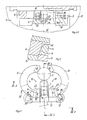
- the jaw chuck is used for eccentric clamping of crankshafts, the axially seen outline of which is indicated at 1.
- the clamping axis 2 runs parallel and eccentrically to the axis of rotation 3 of the chuck.
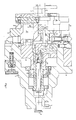
- the chuck itself consists in its basic structure of a coaxial to the axis of rotation 3 attachable to a lathe spindle, not shown Chuck base 4, a clamping head 5 with clamping jaws 6, 7, which is displaceably held on the chuck base parallel to the central plane passing through the axis of rotation 3 and the clamping axis 2 and enables the eccentricity of the clamping axis 2 to be adjusted with respect to the axis of rotation 3, and also with the unbalance of the clamping head 5 balancing counterweights 8, which are guided on the clamping head 5 in the same adjustment direction as this, and from straightening jaws 9, with which the workpiece 1 can be pre-aligned before it is clamped between the clamping jaws 6, 7.
- the clamping jaws 6, 7 are guided in the clamping head 5, namely, first of all, there are two clamping jaws 6, which are arranged mirror-symmetrically to the central plane, are curved in a circular arc around curvature axes 10 parallel to the clamping axis 2 and are adjustable by pivoting about their curvature axis 10 against the clamping axis 2, as well as a central clamping jaw 7, which is driven centrally in the clamping stroke with the two arcuate clamping jaws 6 and which is guided so as to be radially adjustable in relation to the clamping heads 41 of the clamping jaws 6 in the central plane and in relation to the clamping axis 2.
- a drive member 11 is axially adjustable in the chuck base 4, to which an actuating piston 12, which is axially guided in the clamping head 4 and has a clamping wedge body 13, is connected, the clamping jaws 6, 7 each having their own, oblique Clamping surfaces 14, 15 are inclined to the clamping axis 2.
- An actuating member 15 for the straightening jaws 9 is nested in the chuck base 4 in the drive member 11 for the clamping jaws 6, 7, on which actuating bolts 16, which are displaceable in the clamping head 5, are suspended in the same direction as the clamping head 5 axially guided and are formed at their front end with a wedge head 17 which engage in a corresponding wedge receptacle 18 of the straightening jaws 9.
- the connection of the tip 20 or the straightening jaws 9 to their respective actuators 15, 19 cannot hinder the displacement of the clamping head 5 on the chuck base 4.
- the actuating piston 12 is suspended on the driving member 11 for the clamping jaws 6, 7, so that the actuating piston 12 together with the clamping head 5 can move relative to the chuck base 4 and the driving member 11, if that has a yoke 22 on the chuck base 4 mounted adjusting spindle 23 is rotated, which engages in a nut 24 provided with bush 24 of the clamping head 5.
- an externally rotatable shaft 25 with a gear 26 is mounted in the clamping head 5 diametrically opposite the adjusting spindle 23, which meshes with intermediate gears 26 'with a spindle 27 also mounted in the clamping head 5, which in the counterweights 8 engages in a nut thread 28. If the adjusting spindle 23 and the gear shaft 25 are rotated as a result, the clamping head 5 or the counterweights 8 are adjusted parallel to one another.
- the clamping wedge body 13 has two lateral clamping surfaces 14 for the corresponding sloping surfaces 14 'adjacent ends of the circular arc-shaped clamping jaws 6 and centrally between them a groove-like recess 31 in which the central clamping jaw 7 runs.
- the path of all clamping jaws 6, 7 during the clamping stroke can be adjusted exactly to one another and coordinated with one another, so that there is a central clamping movement of all three clamping jaws related to the clamping axis 2 6, 7 results.
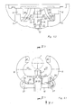
- the actuating piston 12 can then perform a quick stroke for the clamping stroke of all clamping jaws 6, 7 only for the two circular-shaped clamping jaws 6, in order to open these circular-shaped clamping jaws completely for the tool holder, so that the tool can be seen from the side between the open circular-curved clamping jaws 6 the chuck can be inserted.
- the clamping wedge body 13 engages only on the way of the clamping stroke, but on the way of the quick stroke it is detached from this clamping jaw 7, as the comparison of FIG. 4.3 and 5.3 can be recognized immediately.
- the middle clamping jaw 7 In order to prevent the unhooked condition that the middle clamping jaw 7 executes independent movements which could subsequently prevent the wedge teeth 32 from re-entering the driving groove 33 during the clamping stroke, the movement of the middle clamping jaw 7 is limited, for which purpose a stop screw 34 in FIG. 1 on the central clamping jaw 7 engages in a limiting groove 35 provided in the clamping head 5.
- the spline teeth 32 are provided with run-in bevels 36 at their end leading into the driving grooves 33.
- the opening stroke of the clamping stroke and the closing and opening stroke of the quick stroke do not take place for the circular jaws 6 over the clamping surfaces 14, rather the actuating piston 12 overlaps the ends of the circular jaws 6, each with an arm 37, on which a projection 38 in the form of a Bolt is located, which engages in an inclined groove 39 inclined to the clamping axis 2, the length of which is equal to the travel sum of the clamping and rapid stroke, the inclination of the inclined groove 39 being chosen in the same sense as that of the clamping surface 14 and along the path 39.1 corresponding to the clamping stroke is less than on the path 39.2 corresponding to the rapid stroke.
- the clamping wedge body 13 has recesses 40 which accommodate the ends of the circular clamping jaws 6 when these jaws 6 are in the fully open position at the end of overdrive. The complete opening of the circular jaws 6 is thus not hindered by the clamping wedge body 13.
- the clamping jaws 6, 7 all have the same thickness in the axial direction and are arranged perpendicular to the axial direction in essentially the same plane. You can not beak open during the clamping process, so that a reaction-free central clamping of the workpiece 1 is ensured.
Landscapes
- Engineering & Computer Science (AREA)
- Mechanical Engineering (AREA)
- Gripping On Spindles (AREA)
Applications Claiming Priority (2)
| Application Number | Priority Date | Filing Date | Title |
|---|---|---|---|
| DE3828162A DE3828162A1 (de) | 1988-08-19 | 1988-08-19 | Kraftbetaetigtes backenspannfutter fuer exzentrisch zu spannende werkstuecke |
| DE3828162 | 1988-08-19 |
Publications (3)
| Publication Number | Publication Date |
|---|---|
| EP0355256A2 true EP0355256A2 (fr) | 1990-02-28 |
| EP0355256A3 EP0355256A3 (en) | 1990-11-14 |
| EP0355256B1 EP0355256B1 (fr) | 1992-07-08 |
Family
ID=6361174
Family Applications (1)
| Application Number | Title | Priority Date | Filing Date |
|---|---|---|---|
| EP89106092A Expired - Lifetime EP0355256B1 (fr) | 1988-08-19 | 1989-04-07 | Mandrin de serrage excentrique de pièces |
Country Status (5)
| Country | Link |
|---|---|
| US (1) | US4966375A (fr) |
| EP (1) | EP0355256B1 (fr) |
| JP (1) | JPH0276610A (fr) |
| DE (2) | DE3828162A1 (fr) |
| ES (1) | ES2033042T3 (fr) |
Cited By (2)
| Publication number | Priority date | Publication date | Assignee | Title |
|---|---|---|---|---|
| ITBO20090627A1 (it) * | 2009-09-29 | 2011-03-29 | Istonio S R L | Mandrino per la lavorazione di pezzi meccanici |
| CN112894616A (zh) * | 2020-12-04 | 2021-06-04 | 苏州洲洋精密机械科技有限公司 | 一种挑线曲柄自动夹持定位装置 |
Families Citing this family (7)
| Publication number | Priority date | Publication date | Assignee | Title |
|---|---|---|---|---|
| DE4132841A1 (de) * | 1991-10-02 | 1993-04-08 | Boehringer Werkzeugmaschinen | Spannfutter |
| US5320365A (en) * | 1992-10-05 | 1994-06-14 | Sil Han | Precision air chuck with split cam actuator assembly |
| ATE217828T1 (de) * | 1996-05-10 | 2002-06-15 | Kummer Freres Sa | Werkzeugmaschine mit exzenterspindel |
| DE10019775A1 (de) * | 2000-04-20 | 2001-10-31 | Index Werke Kg Hahn & Tessky | Werkzeugmaschine und Werkstückspannfutter |
| JP2005111593A (ja) * | 2003-10-06 | 2005-04-28 | Nsk Ltd | チャック装置及びそれを用いた加工装置 |
| JP6292890B2 (ja) * | 2014-01-15 | 2018-03-14 | コマツNtc株式会社 | チャック装置 |
| CN114799956A (zh) * | 2021-12-23 | 2022-07-29 | 广州市锐美汽车零部件有限公司 | 一种用于数控车床的夹具模块及工件夹持方法 |
Family Cites Families (7)
| Publication number | Priority date | Publication date | Assignee | Title |
|---|---|---|---|---|
| DE422198C (de) * | 1921-07-19 | 1925-11-25 | Felix Rosenberg | Spannfutter mit seitlicher Einfuehrung des Werkstueckes |
| US3373641A (en) * | 1965-04-22 | 1968-03-19 | Leblond Mach Tool Co R K | Chuck construction |
| US4044638A (en) * | 1974-10-31 | 1977-08-30 | Crankshaft Machine Company | Crankshaft machine stock and chuck apparatus |
| FR2430292A1 (fr) * | 1978-07-07 | 1980-02-01 | Clichy Const Sa | Dispositif support d'arbre vilebrequin a quatre manetons sur machine a rectifier |
| JPS59142006A (ja) * | 1983-02-03 | 1984-08-15 | Toyoda Mach Works Ltd | クランク軸を保持するチヤツク |
| DE3446687A1 (de) * | 1984-12-21 | 1986-07-03 | Günter Horst 7927 Sontheim Röhm | Kraftbetaetigtes backenspannfutter fuer exzentrisch zu spannende werkstuecke |
| JPS61152306A (ja) * | 1984-12-25 | 1986-07-11 | Toyoda Mach Works Ltd | クランク軸用偏心チヤツク装置 |
-
1988
- 1988-08-19 DE DE3828162A patent/DE3828162A1/de active Granted
-
1989
- 1989-04-07 EP EP89106092A patent/EP0355256B1/fr not_active Expired - Lifetime
- 1989-04-07 DE DE8989106092T patent/DE58901805D1/de not_active Expired - Lifetime
- 1989-04-07 ES ES198989106092T patent/ES2033042T3/es not_active Expired - Lifetime
- 1989-07-28 US US07/387,173 patent/US4966375A/en not_active Expired - Fee Related
- 1989-08-02 JP JP1201142A patent/JPH0276610A/ja active Pending
Cited By (2)
| Publication number | Priority date | Publication date | Assignee | Title |
|---|---|---|---|---|
| ITBO20090627A1 (it) * | 2009-09-29 | 2011-03-29 | Istonio S R L | Mandrino per la lavorazione di pezzi meccanici |
| CN112894616A (zh) * | 2020-12-04 | 2021-06-04 | 苏州洲洋精密机械科技有限公司 | 一种挑线曲柄自动夹持定位装置 |
Also Published As
| Publication number | Publication date |
|---|---|
| DE3828162A1 (de) | 1990-03-08 |
| DE3828162C2 (fr) | 1991-05-02 |
| DE58901805D1 (de) | 1992-08-13 |
| US4966375A (en) | 1990-10-30 |
| JPH0276610A (ja) | 1990-03-16 |
| EP0355256A3 (en) | 1990-11-14 |
| EP0355256B1 (fr) | 1992-07-08 |
| ES2033042T3 (es) | 1993-03-01 |
Similar Documents
| Publication | Publication Date | Title |
|---|---|---|
| DE3434009C2 (fr) | ||
| DE9313602U1 (de) | Zweifach-Werkzeugträger für Handbohrmaschinen | |
| DE2326546C3 (de) | Schnellspannelement | |
| DE69623630T2 (de) | Werkzeug zum bearbeiten von rohrenden | |
| EP0185883B1 (fr) | Mandrin à mors actionné mécaniquement | |
| DE3828162C2 (fr) | ||
| DE69901662T2 (de) | Maschinen zum Verdrillen von Stäben mit vieleckigem Querschnitt | |
| DE848141C (de) | Maschine zum Schneiden von Blech oder aehnlichem Material | |
| DE2719447C2 (de) | Spannvorrichtung | |
| DE3100512C2 (de) | Schnellwechselfutter | |
| EP1238730A1 (fr) | Mandrin de serrage | |
| DE3844343C2 (de) | Kraftbetätigtes Backenspannfutter für exzentrisch zu spannende Werkstücke, insbesondere Kurbelwellen | |
| DE10143387B4 (de) | Werkzeugkopf für den Einsatz in Werkzeugmaschinen | |
| DE3934365C1 (en) | Grinder tool for dental instruments - has tool body to coaxially enclose support and holder | |
| DE19533730A1 (de) | Räumvorrichtung und Verfahren zum Räumen | |
| DE3631455A1 (de) | Automatischer schraubenschluessel | |
| EP0249184B1 (fr) | Dispositif à fileter | |
| DE3149755A1 (de) | Werkstueckspannvorrichtung | |
| DE2751791C3 (de) | Werkstoffstangenführungseinrichtung für selbsttätige, Mehrkantwerkstoffstangen verarbeitende Drehmaschinen | |
| DE2220161A1 (de) | Vorrichtung zum umsetzen von teilen, insbesondere werkzeugwechselvorrichtung bei werkzeugmaschinen | |
| DE8026616U1 (de) | Schneidwerkzeug, insbesondere zum Entfernen des Sekundärgrates beim maschinellen Entgraten oder Brechen der Stirnkanten der Zähne von Zahnrädern u.a. Teilen | |
| DE1800271C3 (de) | Spannfutter tür Drehmaschinen | |
| DE3618620A1 (de) | Vorrichtung zum automatischen zufuehren und eindrehen von schrauben | |
| DE1299491B (de) | Selbsttaetige Nachformfraesmaschine zur Umrissbearbeitung planer Werkstuecke wie Brillengestelle u. dgl. | |
| DE379861C (de) | Vorrichtung zur Bearbeitung von Kurbelwellen auf einer gewoehnlichen Drehbank |
Legal Events
| Date | Code | Title | Description |
|---|---|---|---|
| PUAI | Public reference made under article 153(3) epc to a published international application that has entered the european phase |
Free format text: ORIGINAL CODE: 0009012 |
|
| AK | Designated contracting states |
Kind code of ref document: A2 Designated state(s): DE ES FR GB IT SE |
|
| PUAL | Search report despatched |
Free format text: ORIGINAL CODE: 0009013 |
|
| AK | Designated contracting states |
Kind code of ref document: A3 Designated state(s): DE ES FR GB IT SE |
|
| 17P | Request for examination filed |
Effective date: 19901116 |
|
| 17Q | First examination report despatched |
Effective date: 19910830 |
|
| GRAA | (expected) grant |
Free format text: ORIGINAL CODE: 0009210 |
|
| AK | Designated contracting states |
Kind code of ref document: B1 Designated state(s): DE ES FR GB IT SE |
|
| REF | Corresponds to: |
Ref document number: 58901805 Country of ref document: DE Date of ref document: 19920813 |
|
| ITF | It: translation for a ep patent filed | ||
| ET | Fr: translation filed | ||
| GBT | Gb: translation of ep patent filed (gb section 77(6)(a)/1977) | ||
| REG | Reference to a national code |
Ref country code: ES Ref legal event code: FG2A Ref document number: 2033042 Country of ref document: ES Kind code of ref document: T3 |
|
| PLBE | No opposition filed within time limit |
Free format text: ORIGINAL CODE: 0009261 |
|
| STAA | Information on the status of an ep patent application or granted ep patent |
Free format text: STATUS: NO OPPOSITION FILED WITHIN TIME LIMIT |
|
| 26N | No opposition filed | ||
| EAL | Se: european patent in force in sweden |
Ref document number: 89106092.3 |
|
| PGFP | Annual fee paid to national office [announced via postgrant information from national office to epo] |
Ref country code: SE Payment date: 19990322 Year of fee payment: 11 |
|
| PGFP | Annual fee paid to national office [announced via postgrant information from national office to epo] |
Ref country code: FR Payment date: 19990323 Year of fee payment: 11 |
|
| PGFP | Annual fee paid to national office [announced via postgrant information from national office to epo] |
Ref country code: GB Payment date: 19990326 Year of fee payment: 11 |
|
| PGFP | Annual fee paid to national office [announced via postgrant information from national office to epo] |
Ref country code: ES Payment date: 19990409 Year of fee payment: 11 |
|
| PGFP | Annual fee paid to national office [announced via postgrant information from national office to epo] |
Ref country code: DE Payment date: 19990612 Year of fee payment: 11 |
|
| PG25 | Lapsed in a contracting state [announced via postgrant information from national office to epo] |
Ref country code: GB Free format text: LAPSE BECAUSE OF NON-PAYMENT OF DUE FEES Effective date: 20000407 |
|
| PG25 | Lapsed in a contracting state [announced via postgrant information from national office to epo] |
Ref country code: SE Free format text: LAPSE BECAUSE OF NON-PAYMENT OF DUE FEES Effective date: 20000408 Ref country code: ES Free format text: THE PATENT HAS BEEN ANNULLED BY A DECISION OF A NATIONAL AUTHORITY Effective date: 20000408 |
|
| GBPC | Gb: european patent ceased through non-payment of renewal fee |
Effective date: 20000407 |
|
| EUG | Se: european patent has lapsed |
Ref document number: 89106092.3 |
|
| PG25 | Lapsed in a contracting state [announced via postgrant information from national office to epo] |
Ref country code: FR Free format text: LAPSE BECAUSE OF NON-PAYMENT OF DUE FEES Effective date: 20001229 |
|
| PG25 | Lapsed in a contracting state [announced via postgrant information from national office to epo] |
Ref country code: DE Free format text: LAPSE BECAUSE OF NON-PAYMENT OF DUE FEES Effective date: 20010201 |
|
| REG | Reference to a national code |
Ref country code: FR Ref legal event code: ST |
|
| REG | Reference to a national code |
Ref country code: ES Ref legal event code: FD2A Effective date: 20020204 |
|
| PG25 | Lapsed in a contracting state [announced via postgrant information from national office to epo] |
Ref country code: IT Free format text: LAPSE BECAUSE OF NON-PAYMENT OF DUE FEES Effective date: 20050407 |