EP0356864B1 - Vorrichtung zum Einstellen der Bogenlage - Google Patents
Vorrichtung zum Einstellen der Bogenlage Download PDFInfo
- Publication number
- EP0356864B1 EP0356864B1 EP89115377A EP89115377A EP0356864B1 EP 0356864 B1 EP0356864 B1 EP 0356864B1 EP 89115377 A EP89115377 A EP 89115377A EP 89115377 A EP89115377 A EP 89115377A EP 0356864 B1 EP0356864 B1 EP 0356864B1
- Authority
- EP
- European Patent Office
- Prior art keywords
- sheet
- checker
- conveying
- sheets
- guiding
- Prior art date
- Legal status (The legal status is an assumption and is not a legal conclusion. Google has not performed a legal analysis and makes no representation as to the accuracy of the status listed.)
- Expired - Lifetime
Links
Images





Classifications
-
- B—PERFORMING OPERATIONS; TRANSPORTING
- B65—CONVEYING; PACKING; STORING; HANDLING THIN OR FILAMENTARY MATERIAL
- B65H—HANDLING THIN OR FILAMENTARY MATERIAL, e.g. SHEETS, WEBS, CABLES
- B65H9/00—Registering, e.g. orientating, articles; Devices therefor
- B65H9/16—Inclined tape, roller, or like article-forwarding side registers
- B65H9/163—Tape
-
- B—PERFORMING OPERATIONS; TRANSPORTING
- B41—PRINTING; LINING MACHINES; TYPEWRITERS; STAMPS
- B41J—TYPEWRITERS; SELECTIVE PRINTING MECHANISMS, i.e. MECHANISMS PRINTING OTHERWISE THAN FROM A FORME; CORRECTION OF TYPOGRAPHICAL ERRORS
- B41J13/00—Devices or arrangements of selective printing mechanisms, e.g. ink-jet printers or thermal printers, specially adapted for supporting or handling copy material in short lengths, e.g. sheets
- B41J13/26—Registering devices
- B41J13/32—Means for positioning sheets in two directions under one control, e.g. for format control or orthogonal sheet positioning
-
- B—PERFORMING OPERATIONS; TRANSPORTING
- B65—CONVEYING; PACKING; STORING; HANDLING THIN OR FILAMENTARY MATERIAL
- B65H—HANDLING THIN OR FILAMENTARY MATERIAL, e.g. SHEETS, WEBS, CABLES
- B65H5/00—Feeding articles separated from piles; Feeding articles to machines
- B65H5/02—Feeding articles separated from piles; Feeding articles to machines by belts or chains, e.g. between belts or chains
- B65H5/021—Feeding articles separated from piles; Feeding articles to machines by belts or chains, e.g. between belts or chains by belts
- B65H5/026—Feeding articles separated from piles; Feeding articles to machines by belts or chains, e.g. between belts or chains by belts between belts and stationary pressing, supporting or guiding elements forming a transport nip
-
- B—PERFORMING OPERATIONS; TRANSPORTING
- B65—CONVEYING; PACKING; STORING; HANDLING THIN OR FILAMENTARY MATERIAL
- B65H—HANDLING THIN OR FILAMENTARY MATERIAL, e.g. SHEETS, WEBS, CABLES
- B65H9/00—Registering, e.g. orientating, articles; Devices therefor
- B65H9/06—Movable stops or gauges, e.g. rising and falling front stops
-
- B—PERFORMING OPERATIONS; TRANSPORTING
- B65—CONVEYING; PACKING; STORING; HANDLING THIN OR FILAMENTARY MATERIAL
- B65H—HANDLING THIN OR FILAMENTARY MATERIAL, e.g. SHEETS, WEBS, CABLES
- B65H9/00—Registering, e.g. orientating, articles; Devices therefor
- B65H9/14—Retarding or controlling the forward movement of articles as they approach stops
Definitions
- the present invention relates to an apparatus for adjusting the posture of conveyed sheets according to the preamble of claim 1.
- Such an apparatus is known from JP-A-61-51445.
- the apparatus may be used in a printer.
- the JP-A-100047/1983 discloses a device including a stationary checking member which is arranged such that fed sheets will collide against the member and their skewed posture can thereby be corrected. Specifically, upon collision each sheet is brought into a posture in which its leading edge is correctly positioned, and possible skewed postures of sheets being fed may thus be corrected.
- the JP-A-190144/1984 discloses another device for correcting skewed posture of fed sheets in a manner similar to that in which the device of the previously mentioned publication does.
- This device further comprises a sensor for detecting the thickness of sheets, for instance, by means of transmitted light therethrough, for the purpose of achieving optimum correction of skewed posture of sheets being fed.
- the force acting between a checking member and a sheet colliding against the checking member is adjusted by controlling the force for conveying the sheet depending on the detected thickness of the sheet.
- the JP-A-90343/1982 proposes a device for registering sides of sheets being fed.
- the device comprises a side registration guide.
- Each fed sheet is once turned aside so that a front corner thereof will not collide against the guide while being conveyed, and subsequently its direction of travel is again turned so as to bring a side of the sheet into contact with the guide, thereby positioning the sheet.
- Another device is also known in which a corners or a side of each sheet is directly brought into contact with a guide without being once separated therefrom in order to register the sides of the sheets.
- Prior art document JP-A-61-51445 discloses an apparatus for adjusting the posture and position of a sheet being conveyed in a predetermined conveyance path.
- This apparatus includes a pair of transport rollers for feeding the sheet obliquely to the direction of the conveyance path. Behind the transport rollers there are provided two endless conveying belts also extending obliquely to the conveyance path.
- Checker members are mounted on each conveying belt in a perpendicular direction to a bar-like guiding member disposed on one side of the conveyance path.
- Prior art document JP-A-57-90343 discloses to bring the side edge of a conveyed sheet into contact with a guiding means after a front corner of this sheet has passed a front edge of the guiding means.
- Prior art document FR-2 041 896 discloses a device for slowing down conveyed sheets. This device comprises abuting means mounted on chains that are driven independently from paper conveying belts.
- the above-mentioned device using the side registration guide has problems in that the sheet transport path becomes long and the movement of the sheet along the path is therefore complicated, or in that the sheet may be deformed off from the plane in which the sheet is conveyed, or the sheet corners may be folded.
- An object of the present invention is therefore to provide a method which allows correcting any skewed posture of a sheet being conveyed without requiring the detection of the thickness thereof, positioning the sides of the sheet being conveyed in a short conveying path without deforming or folding the sheet and properly adjusting the conveyed sheet into a predetermined posture irrespectively of the type of the sheet.
- a further object of the present invention is to provide apparatuses for implementing the above-mentioned methods to be provided by the present invention.
- Checking members are so constructed and arranged to be movable in the direction in which a sheet is conveyed that the members are once driven before coming into contact with the sheet, subsequently decelerated, and brought to abut against the leading edge of the sheet while being decelerated.
- the collision of the checking member with the sheet will cause only a reduced force exerting therebetween, hardly causing a bound or buckling of the sheet, and therefore highly accurate control can be performed within a short time.
- the detection of the sheet is not necessitated, malfunctioning caused by erroneous detection will not occur.
- the sheet For the purpose of positioning the sides of a sheet, the sheet is conveyed while being guided such that its front corner cannot collide with a side registration guide, and the sheet is conveyed toward the guide so as to cause the sheet side to touch the guide after the front corner of the sheet have passed at least an edge of the guide.
- a side registration guide For the purpose of positioning the sides of a sheet, the sheet is conveyed while being guided such that its front corner cannot collide with a side registration guide, and the sheet is conveyed toward the guide so as to cause the sheet side to touch the guide after the front corner of the sheet have passed at least an edge of the guide.
- An apparatus for adjusting the posture of a sheet being conveyed comprises conveyer means defining a conveying path for conveying the sheet therealong; movable checking means provided adjacent to the conveying path for correcting skew of the sheet being conveyed; means for driving the checking means and for controlling movement of the checking means; the driving and controlling means controlling the checking means in such a manner that the driving and controlling means once drives and subsequently decelerates the checking means in the same direction as that in which the sheet is conveyed, and the driving and controlling means causes the checking means to abut against a leading edge of the sheet during the deceleration of the checking means so that the collision of the sheet with the checking means can be moderated; means provided adjacent to the conveying path for positioning a side of the sheet; means for guiding the sheet such that the sheet will not be brought into contact with the positioning means; means for bringing the side of the sheet into contact with the positioning means after a front corner of the sheet have passed by a front edge of the positioning means facing the conveying direction for the sheet.
- Fig. 1 shows the overall arrangement of the apparatus according to an embodiment of the invention.
- the apparatus has a pair of substantially parallel side plates 11, only one of which is illustrated in the drawing.
- a conveyer belt driving shaft 3 and a driven shaft 1 are rotatably supported on the side plates. These shafts 1 and 3 have pulleys mounted thereon, on which a plurality of conveyer belts are wound.
- the present embodiment includes three belts 51, 52 and 53.
- a motor 61 connected to the conveyer belt driving shaft 3 serves to rotate the conveyer belts 51, 52 and 53.
- a pile of a large number of stacked sheets 2 is mounted on a hopper adjacent to the conveyer belts.
- the sheets 2 are taken out of the pile, one by one, by separating means, and are sequentially transported in a spaced relation into the gap between a guide plate 12 and the conveyer belts 51, 52 and 53.
- separating means With respect to the guide plate 12 and the separating means, a description will be given later.
- checking members 21 and 22 for controlling the movement of the paper sheets 2, which are arranged, respectively, between the conveyer belts 51 and 52, and between 52 and 53.
- the checking members 21 and 22 are fixed to checker supporting belts 23 and 24, respectively, and move together with these belts.
- the checking members 21 and 22 and the checking member supporting belts 23 and 24 constitute skew correcting means 20.
- the checking members 21 and 22 are also arranged in locations which bisect the checking member supporting belts 23 and 24.
- the checker supporting belts 23 and 24 can be moved by an checker driving shaft 7 which is rotatably supported on the side plates 11.
- An optical sensor 10 which serves to detect the presence of the paper sheet 2, is provided within the conveying path and upstream of the upstream end of the regions within which the checking members 21 and 22 can be moved, in a manner not interfering with the movement of the sheets 2.
- the optical sensor 10 delivers an output signal when it has detected the front end of the sheet 2, and the output signal triggers the actuation of a motor 62 connected to the checker driving shaft 7.
- a conveyer roller shaft 8 Downstream of the conveyer belts 51, 52 and 53 and the checking members 21 and 22, there are provided a conveyer roller shaft 8 which has conveyer rollers 5 mounted thereon, and a driven roller shaft 9 which has driven rollers 6 mounted thereon in a facting manner relative to the conveyer rollers 5.
- These shafts 8 and 9 are rotatably supported on the side plate 11 and another side plate (not shown) which is situated parallel to the illustrated plate 11.
- the conveyer rollers 5 are driven for rotation by means of a motor 63 connected to the conveyer roller shaft 8.
- Control means 60 which is for controlling the speed of rotation of the motors 61, 62 and 63, will deliver control signals depending on signals from other conveyer systems, separating belts to be described, and the previously mentioned optical sensor 10.
- the speeds of rotation of the motors 61 and 63 are controlled to substantially equalize the peripheral speed of each of the conveyer belts and of the conveyer rollers 5 with the conveying speed V at which the sheet 2 is conveyed.
- the drive shaft 3, drive roller shaft 8 and checker drive shaft 7 have individual motors connected thereto.
- a single power source may be arranged to drive, through a power transmission, all the shafts at predetermined speeds.
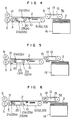
- Figs. 2-6 show the movement of the sheet 2 relative to the movement of the checking members 21 and 22 at sequential points of time in the embodiment.
- Fig. 2 shows the phase in which the sheet 2 is between a separator 15 and the optical sensor 10.
- the sheets 2 stacked in a hopper 16 are separated from the pile of sheets 2 and taken out of the hopper 16 one after another by the separator 15.
- the separator 15 comprises a suction chamber 13 communicating with a vacuum suction device (not shown), and a separating belt 14 having suction ports therethrough and wound around a drive pulley 31 and a driven pulley 32.
- the suction ports through the separating belt 14 are intermittently brought into register with the suction chamber 31 as the belt rotates, and such register causes one sheet 2 on top of the pile of sheets 2 to be drawn to and held by the separating belt 14.
- the sheets 2 are thus delivered one after another onto the conveyer belts 51, 52 and 53.
- the guide plate 12 provided above and spaced from the conveyer belts by a constant distance, serves as a guide for preventing the sheet from rising off the belts 51, 52 and 53.
- Each sheet 12 delivered to between the guide plate 12 and the conveyer belts 51, 52 and 53 is conveyed by the conveyer belts 51, 52 and 53.
- the optical sensor 10 will detect the front end of each sheet 2 passing by the sensor 10 and deliver a detection signal to a control circuit for controlling the driver for driving the checking members 21 and 22 for rotation.
- the checking members 21a (22a) and 21b (22b) are situated to bisect the checker supporting belt 23 (24).
- the checker members 21a (22a) and 21b (22b) are positioned below the top surface of the conveyer belts 51, 52 and 53 and remain there until the optical sensor 10 detects a sheet 2 passing thereby and the control means 60 receives a detection signal from the sensor 10.
- Fig. 3 shows a subsequent phase in which the optical sensor 10 detects the front end of a sheet 2 and the checker members 21a (22a) and 21b (22b) are actuated.
- a checker controlling unit of the control means 60 will actuate the checker driving shaft 7 by means of the motor 62, the checker members 21a (22a) is thus accelerated to above the top surface of the conveyer belts at a location downstream of the detected sheet 2.
- the checker member 21a (22a) is accelerated to near the conveying speed at which the sheet is conveyed, and such member is subsequently decelerated.
- the sheet 2 comes to touch the checker 21a (22a), as shown in Fig. 4, and thus the sheet conveying speed V is thus dominated by the speed of the checker 21a (22a).
- the skew of the sheet 2 is corrected by the checker members 21 and 22 which push the sheet 2 at its front end during the deceleration of the checkers 21 and 22, as shown in Fig. 4.
- the checkers 21a (22a) is further decelerated to stop at the position shown in Fig. 5.
- Fig. 5 shows the sheet 2 stopped.
- the checker 21a (22a) Upon reception by the control means 60 of an open-checkers signal from a central processing unit (not shown), the checker 21a (22a) is accelerated faster than the sheet 2 and thus rotates to a waiting position shown in Fig. 2.
- Fig. 6 shows the phase in which the checker 21a (22a) is out of the conveying path.
- the other checker 21b acts in the same manner as the checker 21a (22a).
- Fig. 7 shows the movement of the checkers 21a (22a) and 21b (22b) based on the signals from the control means 60 in terms of the speed of the checkers varying with time.
- time is taken along the axis of abscissas and the speed V is taken along the axis of ordinates.
- the checker drive shaft 7 Upon detection of the front end of each sheet 2 by the optical sensor 10, the checker drive shaft 7 is actuated for rotation (at point O ) and is accelerated (between points O - a ), and is subsequently driven at a constant speed near the conveying speed V at which the sheet 2 is conveyed (between points a and b ).
- the checker drive shaft 7 is gradually decelerated (between points b and c ) and then stops (at point c ).
- the checker member 21a (22a) or 21b (22b) will be brought into contact with the sheet 2 and thus the skew of the sheet 2 is corrected in a manner as described previously.
- the control means 60 receives a printing signal from the central processing unit at point d and the checker drive shaft 7 is accelerated between points d and e and subsequently decelerated between points e and f to stop at the waiting position.
- the checker drive shaft 7 is again started for rotation at point g , and is accelerated between points g and h and subsequently, between points h and i , it is driven at a constant speed near the conveying speed V for the sheet 2.
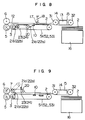
- Fig. 8 shows the apparatus according to another embodiment of the present invention.
- elements identical or similar to those of the previous embodiment are designated by the same reference numerals and will not be described in detail again.
- the apparatus shown in Fig. 8 has an arrangement in which a stronger force may be exerted for conveying sheets.
- a stronger force may be exerted for conveying sheets.
- the conveying force acting between the conveyer belts 51, 52 and 53 and each sheet 2 is not sufficient, it is possible to enhance the conveying force by providing an auxiliary roller 17 urged by a spring 18 against the sheet conveyer, as shown in Fig. 8.
- the guide plate may be pressed against the conveyer belts 51, 52 and 53 by a constant pressing force to enhance the conveying force acting between the sheet 2 and the conveyer belts 51, 52 and 53.
- Fig. 9 shows the apparatus according to a further embodiment of the present invention.
- skew correcting means 20 is arranged opposite to the top surface of the conveying path of the conveyer means.
- the skew correcting means 20, like that of the previously described embodiments, can be rotated about the drive shaft 7.
- the checker member 21a (22a) or 21b (22b) may be caused to project into the conveying path. If the sheet 2 is jammed, for example, in the conveying path, the skew correcting means 20 can be rotated about the drive shaft 7. This makes it possible to easily remove the jammed sheet 2 from the conveying path.
- the conveying means comprises three conveyer belts, between which two checker supporting belts are arranged with checker members secured thereto.
- the number of the checker supporting belts is not limited to two and any plurality of supporting belts having checker members secured thereto may be provided.
- the number of the conveyer belts is not limited to three. Further rollers can be used in place of the conveyer belts.
- the means for separating and taking sheets from the hopper one after another is not limited to the previously described one which comprises the suction chamber and the separating belt having the suction ports therethrough. Any means can be used as long as it can separate and take sheets out of the hopper one after another. For example, friction rollers may be used.
- the above described embodiments are arranged so that each sheet being conveyed can be gradually checked. Therefore, they may be applicable to paper sheets of a wide range of thickness and make it possible to correct skew of the paper sheets accurately and within a short period of time.
- these embodiments make it possible to correct skew of paper sheets while securely conveying them one sheet at a time, achieving efficient conveyance of paper sheets.
- a hopper 16 fixed to side plates 11 of the apparatus.
- the hopper 16 is provided with an elevator mechanism (not shown) for vertically moving the stacked sheets 2.
- a compressed air chamber 140 which is adapted to blow an air jet up to the stacked sheets 2, thus making it easier to separate the sheets 2 on the hopper 16 from one another.
- the separator 15 like the one of the previously described embodiments, comprises the suction chamber 13 and the suction-ported belt 14 wound around driving and driven pulleys.
- a plurality of conveyer belts 150 are wound around pulleys which are mounted on a driving shaft 3 and a driven shaft 101.
- a side registration guide 160 is mounted to one of the side plates 11, and the conveyer belts 150 are arranged to extend obliquely so as to gradually near the guide 160.
- the side registration guide 160 has a groove formed in a side thereof which faces the sheet conveying path.
- the groove lies in the plane in which sheets are conveyed.
- the guide is positioned so that each sheet 2 being conveyed in the plane is brought into contact with the guide 160 at the groove surface.
- each separated sheet 2 can be moved smoothly a short distance from the separating station to the side registering station.
- Each sheet 2 is fed along the conveyer belts 150 and obliquely toward the guide 160 after it has passed the overlap rollers 109. The sheet 2 is then guided into the groove in the side registration guide 160.
- the sheet is conveyed while approaching the side registration guide 160 by the obliquely extending conveyer belts 150 and the overlap rollers 109 after it has reached the overlap rollers 109. Until the sheet reaches the overlap rollers 109, it must be fed by the separating belt 14. Therefore, the following relation must hold: L1 ⁇ 1 (1) In order to avoid collision of a corner of the sheet 2 with the side registration guide 160, the following relation: w ⁇ (L2 + L3) ⁇ tan ⁇ (2) must hold with respect to the position of the sheets in the hopper 16 relative to the side registration guide 160.
- the expression (4) is also applicable to apparatuses employing frictional separation means in place of the suction type separator.
- Fig. 12 shows the sheet 2 which is drawn to, thus separated by the separating belt 14 and is conveyed to the overlap rollers 109.
- the sheet 2 is moved straight until it reaches the overlap rollers 109, since it is drawn by vacuum to the separating belt 14.
- the sheet drawing action of the separating belt 14 reduces. Thereafter, the conveying force provided by the overlap rollers 109 and the conveyer belts 150 becomes predominant.
- Fig. 13 shows the sheet 2 being conveyed obliquely. In this condition, however, the front corner of the sheet 2 will not collide with the side registration guide 160.
- Fig. 14 shows the sheet 2 being conveyed with its front end passing through the groove of the side registration guide 160.
- the front end corner of the sheet will not collide with the side registration guide 160.
- one side of the sheet 2 is brought into contact with the groove of the guide 160, whereby the side registration of the sheet is performed.
- the above described embodiment can perform a high precision side registration of sheets in a short conveying path without causing folds of the sheets at the corners thereof or jamming thereof. Therefore, they have an advantage in that printing on a preprinted paper sheet or on the entire surface of a sheet can be performed in a compact arrangement of the embodiment.
- Fig. 15 shows the apparatus according to still another embodiment of the present invention.
- the apparatus shown is a combination of the embodiments shown in Fig. 1 and Fig. 10 and the components of this apparatus are similarly arranged except that the skew correcting means includes three sets of checker members.
- the skew correcting means 20 comprises three sets of checker supporting belts 24, 25 and 26 which respectively have checker members 21, 22 and 23 secured thereto and will operate in the same manner as those of Fig. 1 embodiment does.
- each sheet 2 is side registered by the side registration guide 160 and subsequently comes into contact with the checker members 21, 22 and 23, whereby the sheet is checked at a predetermined position.
- the skew correction of the sheet 2 during conveyance but also the side registration thereof can be performed and thus it is always possible to properly adjust the posture of sheets being conveyed.
Landscapes
- Engineering & Computer Science (AREA)
- Mechanical Engineering (AREA)
- Registering Or Overturning Sheets (AREA)
- Delivering By Means Of Belts And Rollers (AREA)
Claims (8)
- Vorrichtung zur Einstellung der Lage eines geförderten Blatts (2), mit- einer Zuführeinrichtung (15), um die Blätter (2) in beabstandeter Weise zu einer in einem längs ausgerichteten Förderpfad vorgesehenen Einstellstation zu transportieren, wobei die Blätter eine vorbestimmte Länge Lp in Längsrichtung haben,- einer Fördereinrichtung (150), die in der Einstellstation vorgesehen ist, um die Blätter (2) schräg zur Längsrichtung zu fördern,- einer Führeinrichtung (160), die am Förderpfad angrenzend derart angebracht ist, daß eine Seitenkante des schräg geförderten Blatts (2) mit der Führeinrichtung (160) in Kontakt gelangt, und- einer beweglichen Hemmeinrichtung (20), die quer zur Längsrichtung angebracht ist, um eine verdrehte Lage des Blatts (2) durch Kontaktieren der Vorderkante des Blatts zu korrigieren,dadurch gekennzeichnet, daß- die Fördereinrichtung (150) mehrere synchron angetriebene Förderbänder (150) aufweist, die sich schräg unter dem Verdrehwinkel ϑ bezüglich der Längsrichtung erstrecken, sowie Überlappungsrollen (109), die über den Förderbändern (150) und in einem vorbestimmten Abstand L₁ hinter der Zuführeinrichtung (15) sowie einem vorbestimmten Abstand L₂ vor der Führeinrichtung (160) angebracht sind,- die Führeinrichtung (160) eine vorbestimmte Länge L₃ hat und in einer solchen vorbestimmten seitlichen Position bezüglich der Fördereinrichtung (150) angebracht ist, daß die Seitenkante des schräg geförderten Blatts die Führeinrichtung (160) kontaktiert, nachdem die Vorderecke des Blatts die Führeinrichtung (160) passiert hat,- die Hemmeinrichtung (20) durch eine Antriebseinrichtung (62) beschleunigt und abgebremst wird, um die Vorderkante des Blatts in Kontakt mit der Hemmeinrichtung (20) zu bringen, nachdem die Vorderkante des Blatts (2) die Führeinrichtung (160) passiert hat, und-


- Vorrichtung nach Anspruch 1,
dadurch gekennzeichnet, daß
die Überlapprollen (109) der Fördereinrichtung im Förderpfad in einer Position hinter der Fördereinrichtung (160) angebracht sind, in der die Führwirkung für das Blatt (2) durch die Führeinrichtung (160) im wesentlichen abgeschlossen ist. - Vorrichtung nach Anspruch 1 oder 2,
dadurch gekennzeichnet, daß
auf der Innenseite der Führeinrichtung (160) ein Längsschlitz zur Aufnahme der Seitenkante des Blatts (2) vorgesehen ist. - Vorrichtung nach einem der Ansprüche 1 bis 3,
dadurch gekennzeichnet, daß
im Förderpfad eine Erfassungseinrichtung (10) vorgesehen ist, um das Vorhandensein eines geförderten Blatts (2) zu erfassen, die mit einer Steuerungseinheit (60) zur Steuerung der Geschwindigkeit der Hemmeinrichtung (20) verbunden ist. - Vorrichtung nach einem der Ansprüche 1 bis 4,
dadurch gekennzeichnet, daß
die Steuerungs- und Antriebseinrichtung (60, 62) die Hemmeinrichtung (20) zumindest bis zur Fördergeschwindigkeit des Blatts (2) beschleunigt und nach einer Periode konstanter Geschwindigkeit die Hemmeinrichtung (20) bremst. - Vorrichtung nach einem der Ansprüche 1 bis 5,
dadurch gekennzeichnet, daß
die Hemmeinrichtung (20) zumindest ein endloses Stützband (24-26) aufweist, das in einer vorbestimmten Beziehung zu den Förderbandvorrichtungen (150) angebracht ist, und daß zumindest ein Hemmbauteil (21-24) am Stützband (24-26) derart angebracht ist, daß das Hemmbauteil (21, 22) unabhängig von der Förderwirkung des Förderbands (150) in den Förderpfad hinein und aus diesem heraus gelangt. - Vorrichtung nach Anspruch 6,
dadurch gekennzeichnet, daß
ein zwei Hemmbauteile (21a, 21b) stützendes endloses Stützband (24-26) zwischen benachbarten Förderbändern (150) angebracht ist. - Vorrichtung nach Anspruch 6,
dadurch gekennzeichnet, daß
ein zwei Hemmbauteile (21a, 21b) stützendes endloses Stützband (23, 24) oberhalb der Förderbänder (150) angebracht ist.
Applications Claiming Priority (2)
| Application Number | Priority Date | Filing Date | Title |
|---|---|---|---|
| JP218345/88 | 1988-09-02 | ||
| JP63218345A JP2624795B2 (ja) | 1988-09-02 | 1988-09-02 | 紙葉類の斜行修正方法 |
Publications (3)
| Publication Number | Publication Date |
|---|---|
| EP0356864A2 EP0356864A2 (de) | 1990-03-07 |
| EP0356864A3 EP0356864A3 (de) | 1991-02-20 |
| EP0356864B1 true EP0356864B1 (de) | 1995-06-21 |
Family
ID=16718416
Family Applications (1)
| Application Number | Title | Priority Date | Filing Date |
|---|---|---|---|
| EP89115377A Expired - Lifetime EP0356864B1 (de) | 1988-09-02 | 1989-08-21 | Vorrichtung zum Einstellen der Bogenlage |
Country Status (5)
| Country | Link |
|---|---|
| US (1) | US5039086A (de) |
| EP (1) | EP0356864B1 (de) |
| JP (1) | JP2624795B2 (de) |
| KR (1) | KR920010799B1 (de) |
| DE (1) | DE68923136T2 (de) |
Families Citing this family (32)
| Publication number | Priority date | Publication date | Assignee | Title |
|---|---|---|---|---|
| JP2535428B2 (ja) * | 1990-04-13 | 1996-09-18 | エス・ケイエンジニアリング株式会社 | シ―ト供給装置 |
| US5172898A (en) * | 1990-07-05 | 1992-12-22 | Mitsubishi Jukogyo Kabushiki Kaisha | Paperboard feeding apparatus |
| US5080666A (en) * | 1990-10-17 | 1992-01-14 | Pitney Bowes Inc. | Document aligning apparatus |
| US5209809A (en) * | 1990-10-26 | 1993-05-11 | Moore Business Forms, Inc. | Detacher to folder or pressure sealer shingle conveyor |
| JPH0494356U (de) * | 1990-12-28 | 1992-08-17 | ||
| US5324124A (en) * | 1993-01-28 | 1994-06-28 | International Business Machines Corporation | Guide system for feed roll entry |
| US5374053A (en) * | 1994-01-21 | 1994-12-20 | Heidelberger Druckmaschinen Ag | Device for changing the transport position of products |
| JP3442859B2 (ja) * | 1994-05-24 | 2003-09-02 | キヤノンファインテック株式会社 | 印刷装置および方法 |
| DE19609991A1 (de) * | 1996-03-14 | 1997-09-18 | Winkler Duennebier Kg Masch | Verfahren und Vorrichtung zum Ausrichten von flachen Gegenständen, insbesondere von Briefumschlägen |
| DE19853026C1 (de) * | 1998-11-18 | 2000-03-30 | Icoma Fbs Gmbh Packtechnik | Vorrichtung zum Ausrichten von Schlauchabschnitten |
| DE10119508C1 (de) * | 2001-04-21 | 2002-10-24 | Fischer Maschf Karl E | Materialführungssystem für Spleißmaschinen |
| US7021185B2 (en) * | 2001-10-26 | 2006-04-04 | Goss International Americas, Inc. | Registration apparatus for a sheet material article handler |
| KR20030038890A (ko) * | 2001-11-07 | 2003-05-17 | 대구중공업주식회사 | 페이퍼 포지셔너 |
| PL212097B1 (pl) * | 2003-03-10 | 2012-08-31 | Diebold Inc | Sposób otwierania drzwiczek kasety i kaseta nośnika dla urządzenia do automatycznego przeprowadzania transakcji bankowych |
| US7537211B2 (en) * | 2004-05-14 | 2009-05-26 | Seiko Epson Corporation | Media transportation mechanism and a data processing apparatus having a media transportation mechanism |
| DE102005046685A1 (de) * | 2005-09-29 | 2007-04-05 | Heidelberger Druckmaschinen Ag | Bogenleiteinrichtung für Bogenanleger |
| JP4302706B2 (ja) * | 2006-03-28 | 2009-07-29 | ホリゾン・インターナショナル株式会社 | 紙折装置 |
| JP5511497B2 (ja) * | 2009-06-30 | 2014-06-04 | キヤノン株式会社 | シート搬送装置及び画像形成装置 |
| EP2277812B1 (de) * | 2009-07-21 | 2013-07-03 | Müller Martini Holding AG | Verfahren zum seitlichen Ausrichten von Produkten mit ebener Grundfläche, insbesondere von Druckprodukten, sowie Transportvorrichtung zum Durchführen des Verfahrens |
| JP5574884B2 (ja) * | 2010-08-25 | 2014-08-20 | キヤノン株式会社 | 画像形成装置 |
| JP5830894B2 (ja) | 2011-03-28 | 2015-12-09 | 富士ゼロックス株式会社 | 記録材搬送装置 |
| JP5790067B2 (ja) * | 2011-03-29 | 2015-10-07 | 富士ゼロックス株式会社 | 用紙搬送装置および画像形成装置 |
| JP5830927B2 (ja) * | 2011-05-13 | 2015-12-09 | 富士ゼロックス株式会社 | 用紙搬送装置 |
| JP5817208B2 (ja) * | 2011-05-16 | 2015-11-18 | 富士ゼロックス株式会社 | 用紙搬送装置及び画像形成装置 |
| JP5849437B2 (ja) | 2011-05-25 | 2016-01-27 | 富士ゼロックス株式会社 | 記録材搬送装置および画像形成装置 |
| TWI457267B (zh) * | 2011-05-30 | 2014-10-21 | Seiko Epson Corp | 搬送裝置、印刷裝置、及搬送方法 |
| JP5958097B2 (ja) * | 2012-06-05 | 2016-07-27 | 富士ゼロックス株式会社 | シート搬送装置、画像形成装置 |
| US9334133B2 (en) * | 2012-06-28 | 2016-05-10 | Multifeeder Technologies, Inc. | Sheet feeder with dual discharge |
| CN103144424B (zh) * | 2013-03-07 | 2016-01-20 | 天津长荣印刷设备股份有限公司 | 一种电子套准系统及其工作方法 |
| US9533489B2 (en) * | 2013-09-23 | 2017-01-03 | Tresu A/S | Apparatus for register control and a method for regulating such apparatus |
| JP2020057036A (ja) * | 2018-09-28 | 2020-04-09 | 日立オムロンターミナルソリューションズ株式会社 | 紙葉類取扱装置、自動取引装置、および紙葉類仕分け装置 |
| CN111591796B (zh) * | 2020-04-28 | 2022-02-18 | 温州职业技术学院 | 一种柔性印刷机的纸间距调节装置 |
Family Cites Families (12)
| Publication number | Priority date | Publication date | Assignee | Title |
|---|---|---|---|---|
| US2039784A (en) * | 1935-05-03 | 1936-05-05 | Cottrell C B & Sons Co | Sheet feed retarding mechanism for printing presses |
| FR824006A (fr) * | 1936-07-08 | 1938-01-31 | Roland Offsetmaschf | Dispositif d'application des feuilles à marger |
| GB1151493A (en) * | 1966-01-25 | 1969-05-07 | Ernest Arthur Timson | Slow-Down Means for Travelling Sheets |
| FR2041896A5 (de) * | 1969-04-21 | 1971-02-05 | Timson Ernest | |
| DE2135271A1 (de) * | 1971-07-15 | 1973-01-25 | Winkler Duennebier Kg Masch | Vorrichtung zum zeitlichen und raeumlichen ausrichten einer fortlaufenden folge fertig- oder teilgefalteter briefhuellen, zuschnitte od.dgl |
| US4147339A (en) * | 1975-03-26 | 1979-04-03 | Ricoh Company, Ltd. | Sheet feed and positioning mechanism |
| JPS5790343A (en) * | 1980-11-20 | 1982-06-05 | Fuji Xerox Co Ltd | Paper adjusting device in duplicating machine |
| JPS58100047A (ja) * | 1981-12-11 | 1983-06-14 | Fuji Xerox Co Ltd | レジストレ−シヨン装置 |
| DE3223048C2 (de) * | 1982-06-19 | 1984-07-05 | Canon K.K., Tokio/Tokyo | Verfahren zum Ausrichten eines durch Walzenpaare laufenden Papierblattes sowie Vorrichtung zur Durchführung des Verfahrens und Anwendung desselben |
| JPS59173863A (ja) * | 1983-03-24 | 1984-10-02 | Fujitsu Ltd | マスクメモリ方式 |
| JPS59190144A (ja) * | 1983-04-12 | 1984-10-27 | Fuji Xerox Co Ltd | 用紙搬送力制御装置 |
| JPS61132352U (de) * | 1985-02-05 | 1986-08-18 |
-
1988
- 1988-09-02 JP JP63218345A patent/JP2624795B2/ja not_active Expired - Fee Related
-
1989
- 1989-08-17 US US07/395,015 patent/US5039086A/en not_active Expired - Fee Related
- 1989-08-21 EP EP89115377A patent/EP0356864B1/de not_active Expired - Lifetime
- 1989-08-21 DE DE68923136T patent/DE68923136T2/de not_active Expired - Fee Related
- 1989-08-28 KR KR1019890012252A patent/KR920010799B1/ko not_active Expired
Also Published As
| Publication number | Publication date |
|---|---|
| KR900004516A (ko) | 1990-04-12 |
| EP0356864A2 (de) | 1990-03-07 |
| JP2624795B2 (ja) | 1997-06-25 |
| JPH0270639A (ja) | 1990-03-09 |
| US5039086A (en) | 1991-08-13 |
| EP0356864A3 (de) | 1991-02-20 |
| DE68923136D1 (de) | 1995-07-27 |
| DE68923136T2 (de) | 1995-11-30 |
| KR920010799B1 (ko) | 1992-12-17 |
Similar Documents
| Publication | Publication Date | Title |
|---|---|---|
| US5039086A (en) | Method and apparatus for adjusting posture of sheets | |
| US5090683A (en) | Electronic sheet rotator with deskew, using single variable speed roller | |
| US5980439A (en) | Folding apparatus | |
| EP0393589A1 (de) | Kontinuierliches Papierausgabegerät | |
| US4621966A (en) | Shingle compensating device | |
| US6942214B2 (en) | Mail registration and feeding apparatus | |
| US5265731A (en) | Job separator | |
| EP0406827A1 (de) | Blattumkehrapparat | |
| US4146220A (en) | Document handling apparatus | |
| US4076233A (en) | Document handling apparatus | |
| JP2723864B2 (ja) | 紙葉類の重ね合わせ機構 | |
| JPS6151445A (ja) | 用紙整合装置 | |
| US5465950A (en) | Paper sheet conveying and arranging apparatus | |
| JP2709623B2 (ja) | シート位置決め装置 | |
| JP3610474B2 (ja) | 紙葉類搬送装置 | |
| EP0537978B1 (de) | Verfahren und Vorrichtung zum Sortieren von abgeschnittenen blattförmigen Materialien in Stapeln | |
| EP3822206B1 (de) | Stapelvorrichtung und sortierverfahren | |
| JP3090134B2 (ja) | 給紙装置および方法 | |
| JP2790889B2 (ja) | ソーター綴じ装置 | |
| JPH02178162A (ja) | 紙葉類の搬送装置 | |
| JP3788052B2 (ja) | 紙葉類整位装置 | |
| JPS6320669Y2 (de) | ||
| JPH0464554A (ja) | 用紙斜行補正機構 | |
| JPH03211147A (ja) | 紙葉類搬送装置のスキュー検知機構 | |
| JPH08192939A (ja) | シート給送装置および画像読み取り装置 |
Legal Events
| Date | Code | Title | Description |
|---|---|---|---|
| PUAI | Public reference made under article 153(3) epc to a published international application that has entered the european phase |
Free format text: ORIGINAL CODE: 0009012 |
|
| AK | Designated contracting states |
Kind code of ref document: A2 Designated state(s): DE FR GB NL |
|
| PUAL | Search report despatched |
Free format text: ORIGINAL CODE: 0009013 |
|
| 17P | Request for examination filed |
Effective date: 19901122 |
|
| AK | Designated contracting states |
Kind code of ref document: A3 Designated state(s): DE FR GB NL |
|
| 17Q | First examination report despatched |
Effective date: 19930302 |
|
| GRAA | (expected) grant |
Free format text: ORIGINAL CODE: 0009210 |
|
| AK | Designated contracting states |
Kind code of ref document: B1 Designated state(s): DE FR GB NL |
|
| REF | Corresponds to: |
Ref document number: 68923136 Country of ref document: DE Date of ref document: 19950727 |
|
| ET | Fr: translation filed | ||
| PLBE | No opposition filed within time limit |
Free format text: ORIGINAL CODE: 0009261 |
|
| STAA | Information on the status of an ep patent application or granted ep patent |
Free format text: STATUS: NO OPPOSITION FILED WITHIN TIME LIMIT |
|
| 26N | No opposition filed | ||
| REG | Reference to a national code |
Ref country code: GB Ref legal event code: IF02 |
|
| PGFP | Annual fee paid to national office [announced via postgrant information from national office to epo] |
Ref country code: FR Payment date: 20020618 Year of fee payment: 14 |
|
| PGFP | Annual fee paid to national office [announced via postgrant information from national office to epo] |
Ref country code: GB Payment date: 20020809 Year of fee payment: 14 |
|
| PGFP | Annual fee paid to national office [announced via postgrant information from national office to epo] |
Ref country code: NL Payment date: 20020830 Year of fee payment: 14 |
|
| PGFP | Annual fee paid to national office [announced via postgrant information from national office to epo] |
Ref country code: DE Payment date: 20021030 Year of fee payment: 14 |
|
| PG25 | Lapsed in a contracting state [announced via postgrant information from national office to epo] |
Ref country code: GB Free format text: LAPSE BECAUSE OF NON-PAYMENT OF DUE FEES Effective date: 20030821 |
|
| PG25 | Lapsed in a contracting state [announced via postgrant information from national office to epo] |
Ref country code: NL Free format text: LAPSE BECAUSE OF NON-PAYMENT OF DUE FEES Effective date: 20040301 |
|
| PG25 | Lapsed in a contracting state [announced via postgrant information from national office to epo] |
Ref country code: DE Free format text: LAPSE BECAUSE OF NON-PAYMENT OF DUE FEES Effective date: 20040302 |
|
| GBPC | Gb: european patent ceased through non-payment of renewal fee | ||
| PG25 | Lapsed in a contracting state [announced via postgrant information from national office to epo] |
Ref country code: FR Free format text: LAPSE BECAUSE OF NON-PAYMENT OF DUE FEES Effective date: 20040430 |
|
| NLV4 | Nl: lapsed or anulled due to non-payment of the annual fee |
Effective date: 20040301 |
|
| REG | Reference to a national code |
Ref country code: FR Ref legal event code: ST |