EP0357245B1 - Dispositif de montage à amortissement hydraulique - Google Patents
Dispositif de montage à amortissement hydraulique Download PDFInfo
- Publication number
- EP0357245B1 EP0357245B1 EP89307936A EP89307936A EP0357245B1 EP 0357245 B1 EP0357245 B1 EP 0357245B1 EP 89307936 A EP89307936 A EP 89307936A EP 89307936 A EP89307936 A EP 89307936A EP 0357245 B1 EP0357245 B1 EP 0357245B1
- Authority
- EP
- European Patent Office
- Prior art keywords
- hydraulically damped
- chamber
- damped mount
- mount
- resilient element
- Prior art date
- Legal status (The legal status is an assumption and is not a legal conclusion. Google has not performed a legal analysis and makes no representation as to the accuracy of the status listed.)
- Expired - Lifetime
Links
- 239000012530 fluid Substances 0.000 claims description 44
- 238000005192 partition Methods 0.000 claims description 22
- 230000002093 peripheral effect Effects 0.000 claims description 13
- 125000006850 spacer group Chemical group 0.000 claims description 12
- 239000002184 metal Substances 0.000 claims description 5
- 238000013016 damping Methods 0.000 description 4
- 101100441413 Caenorhabditis elegans cup-15 gene Proteins 0.000 description 3
- 239000000463 material Substances 0.000 description 3
- 238000006073 displacement reaction Methods 0.000 description 2
- 239000007788 liquid Substances 0.000 description 2
- 238000010276 construction Methods 0.000 description 1
- 230000001627 detrimental effect Effects 0.000 description 1
- 230000000694 effects Effects 0.000 description 1
- 238000010438 heat treatment Methods 0.000 description 1
Images







Classifications
-
- F—MECHANICAL ENGINEERING; LIGHTING; HEATING; WEAPONS; BLASTING
- F16—ENGINEERING ELEMENTS AND UNITS; GENERAL MEASURES FOR PRODUCING AND MAINTAINING EFFECTIVE FUNCTIONING OF MACHINES OR INSTALLATIONS; THERMAL INSULATION IN GENERAL
- F16F—SPRINGS; SHOCK-ABSORBERS; MEANS FOR DAMPING VIBRATION
- F16F13/00—Units comprising springs of the non-fluid type as well as vibration-dampers, shock-absorbers, or fluid springs
- F16F13/04—Units comprising springs of the non-fluid type as well as vibration-dampers, shock-absorbers, or fluid springs comprising both a plastics spring and a damper, e.g. a friction damper
- F16F13/06—Units comprising springs of the non-fluid type as well as vibration-dampers, shock-absorbers, or fluid springs comprising both a plastics spring and a damper, e.g. a friction damper the damper being a fluid damper, e.g. the plastics spring not forming a part of the wall of the fluid chamber of the damper
- F16F13/08—Units comprising springs of the non-fluid type as well as vibration-dampers, shock-absorbers, or fluid springs comprising both a plastics spring and a damper, e.g. a friction damper the damper being a fluid damper, e.g. the plastics spring not forming a part of the wall of the fluid chamber of the damper the plastics spring forming at least a part of the wall of the fluid chamber of the damper
- F16F13/10—Units comprising springs of the non-fluid type as well as vibration-dampers, shock-absorbers, or fluid springs comprising both a plastics spring and a damper, e.g. a friction damper the damper being a fluid damper, e.g. the plastics spring not forming a part of the wall of the fluid chamber of the damper the plastics spring forming at least a part of the wall of the fluid chamber of the damper the wall being at least in part formed by a flexible membrane or the like
-
- F—MECHANICAL ENGINEERING; LIGHTING; HEATING; WEAPONS; BLASTING
- F16—ENGINEERING ELEMENTS AND UNITS; GENERAL MEASURES FOR PRODUCING AND MAINTAINING EFFECTIVE FUNCTIONING OF MACHINES OR INSTALLATIONS; THERMAL INSULATION IN GENERAL
- F16F—SPRINGS; SHOCK-ABSORBERS; MEANS FOR DAMPING VIBRATION
- F16F13/00—Units comprising springs of the non-fluid type as well as vibration-dampers, shock-absorbers, or fluid springs
- F16F13/04—Units comprising springs of the non-fluid type as well as vibration-dampers, shock-absorbers, or fluid springs comprising both a plastics spring and a damper, e.g. a friction damper
- F16F13/26—Units comprising springs of the non-fluid type as well as vibration-dampers, shock-absorbers, or fluid springs comprising both a plastics spring and a damper, e.g. a friction damper characterised by adjusting or regulating devices responsive to exterior conditions
Definitions
- the present invention relates to improvements in hydraulically damped mounts.
- Japanese utility model application No. 63-74856 discloses a fluid damped mounting device which includes a boss fixed to an engine, and a generally annular support fixed to a vehicle frame.
- a resilient element is connected between the boss and the support and co-operates with a diaphragm to define a fluid chamber.
- the fluid chamber is filled with a fluid and divided into a working chamber and a compensation chamber by means of a partition assembly.
- the partition assembly includes two disks joined together in a manner to define a space therebetween.
- a movable plate is arranged within the space and is vertically movable. When the engine vibrates, the resilient element is subject to a flexure. This causes a change in the volume of the working chamber.
- displacement of the movable plate absorbs the movement of the fluid caused by the change in the volume of the working chamber.
- the two disks are likely to flex, particularly at their center, due to fluid pressure. If flexed, movable distance of the movable plate would be reduced, and the movement of the fluid may not be appropriate adsorbed.
- EP-A-0 262 544 discloses a hydraulically damped mounting device having two anchor points joined by a resilient spring.
- the spring and a partition define a working chamber which is in communication with a compensation chamber via a passage.
- a hydraulically damped mount comprising: a mounting element adapted to be fixed to a moving component; a support substantially co-axial with the mounting element and adapted to be fixed to a stationary component; a resilient element connected between said mounting element and said support; a deformable element secured to said support and co-operating with said resilient element so as to define a fluid chamber(s), said fluid chamber being filled with an incompressible fluid; a partition assembly connected to divide said fluid chamber with respect to the axial direction into a working chamber and a compensation chamber and having a passage through which said working chamber and said compensation chamber are communicating with each other; said partition assembly further including, with respect to the axial direction, and upper place and a lower plate spaced apart from each other, said upper and lower plates being secured to the support and joined together to define a space within which a movable plate is movable to absorb movement of the fluid caused by a change in pressure in said working chamber.
- the present invention is characterised in that means is provided for maintaining a constant distance between said upper plate and said lower plate of said partition assembly, said means including a cylindrical spacer centrally disposed in said upper and lower plates.
- a hydraulically damped mount comprises a frustoconical-shaped resilient element interconnected between a mounting element fixed to a moving machine such as a vehicle engine and a support fixed to a stationary support such as a vehicle frame.
- a diaphragm is secured to the support and co-operates with the resilient element to define a fluid chamber filled with an incompressible fluid such as an oil.
- the chamber is divided by a partition assembly into a working chamber and a compensation chamber.
- the partition assembly includes an upper plate and a lower plate joined together in a manner to define a space therebetween.
- a movable plate is arranged within the space and is vertically movable. When small amplitude vibrations are applied to the mounting element, the resilient element is flexed.
- the movable plate then absorbs the movement of the oil caused by the change in the volume of the working chamber.
- a spacer is centrally positioned in the upper and lower plates to maintain a constant distance between the two plates whereby movable range of the movable plate in the vertical direction is always kept constant.
- a press member in the form of an inverted-U cup, is fixed to the mounting element or disk.
- the frustoconical resilient element tends to expand outwardly due to an increase in pressure in the working chamber.
- the press member is adapted to push down the expanded area of the resilient element so as to prevent the undesirable reduction of the effective cross area of the resilient element acting as a piston.
- a protection cover is fixedly attached to the press member to prevent the resilient element from heat, for instance, dissipated from the engine.
- the upper section of the cover is secured to the inner surface of the press member and has an annular recess within which the rim or peripheral edge of the mounting disk is received to hold the cover in position.
- a small opening may also be formed in the movable plate to provide a fluid communication between the inner chamber and the compensation chamber.
- a recess may be formed in the outer peripheral edge of the movable plate.
- a through hole may extend axially through the spacer.
- the volume of the compensation chamber is rendered variable by deformation of the diaphragm to compensate for movement of fluid between the working chamber and the compensation chamber.
- the diaphragm has a relatively low coefficient of elasticity and is more deformable than the resilient element.
- the diaphragm has a thick portion on which an annular ridge is formed. The annular ridge is normally in contact with the lower surface of the lower plate so as to provide a constant distance between the diaphragm and the partition assembly and thus, to keep the volume of the compensation chamber constant.
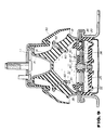
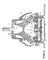
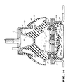
- the mount 10 includes a mounting element or disk 11 connected by a bolt 12 to any moving machine such as a reciprocating engine (not shown) and having a peripheral edge 13 extending over the rim of a cup 15.
- a resilient element or spring element 16 made of rubber or similar material, is of a frustoconical shape and has a central recess 17 within which the cup 15 is received.
- a bracket 18 is secured to the lower part of the resilient element 16 and extends over the rim of a generally cylindrical support 20.
- the support 20 has an annular flange 21 seated on a vehicle frame (not shown) and secured thereto by a fixing bolt (not shown).
- the chamber S is filled with a suitable incompressible fluid such as an oil, and is divided into an upper or a working chamber S1 and a lower or a compensation chamber S2 by means of a partition assembly 27.
- the two plates 30, 31 may be flexed, particularly at their center. Such flexure will change the distance between the two plates, and may prevent proper vertical movement of the movable plate 36.
- a cylindrical spacer 40 made of suitable metal, is placed centrally in the two plates 30, 31 so as to maintain a constant distance or space therebetween.
- the spacer 40 has a large-diameter section 40a, an upper small-diameter section 40b, and a lower small-diameter section 40c.
- a press member 42 cooperates with an annular metal ring 43. More specifically, the press member 42, in the form of an inverted U cup, is fixed by a bolt 44 to the disk 11 and has a flange 42a.
- the mount 10 may be thermally affected, for example, when used as an engine mounting. Heating may change the characteristics of the resilient element 16 and would have a detrimental effect on the behaviour of the mount 10.
- a protection cover 50 is provided to prevent the mount 10 from such heat.
- the cover 50 includes, in a unitary fashion, a lower section or skirt 51 adapted to surround the lower half of the resilient element 16, an intermediate portion 52 within which the flange 42a of the press member 42 is embedded, and an upper cylindrical section 53 secured to the inner peripheral surface of the press member 42 and having at its upper end an annular recess 54 within which the peripheral edge 13 of the disk 11 is received for engagement.
- the cover 50 is attached to the press member 42 before they are assembled to the disk 11.
- the inner diameter of the upper section 53 of the cover 50 gradually increases in a direction toward the partition 27. This arrangement makes it easier to fit the cover/press member over the disk from thereabove.
- the resilient element 16 includes an annular projection 60 extending downwardly from its lower surface. There is also provided an annular projection 61 seated on the upper surface of the upper plate 30 and having a tapered surface 62 and a horizontal surface 63. Both of these projections 60, 61 act as a stopper. When considerably large amplitude vibrations occur, the annular projection 60 is moved into contact with the horizontal surface 63 of the projection 61 and at the same time, the tapered surface 62 of the projection 61 is brought into contact with the lower surface of the resilient element 16, as best seen in Fig. 8. Under these circumstances, the working chamber S1 is divided into an inner chamber S1a and an outer chamber S1b.
- the projection 61 has a plurality of radial grooves 64 formed at circumferentially equally spaced intervals as shown in Fig. 8.
- radial grooves as indicated at 65 in Fig. 9, may be formed, at circumferentially equally spaced intervals, in the lower surface of the resilient element 16.
- Each of these grooves 65 extends from the lower surface of the projection 60 and terminates at near the lower end of the resilient element 16.
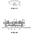
- the diaphragm 25 has a relatively low coefficient of elasticity and is more deformable than the resilient element 16. As shown in Fig. 12, the diaphragm 25 includes a thick portion 25a having a central opening 25b, a ring portion 25c secured to the inner peripheral wall of the support 20, and a thin portion 25d by which the thick portion 25a and the ring 25c are interconnected together.
- the mount 10 is positioned upside down and supported on a member 73.
- a suitable cover 74 is fitted at its peripheral edge into an annular groove 25g formed in the ring 25c and has an inlet 75 to which one end of a flexible hose 76 is connected.
- the other end of the hose 76 is connected to a valve 77 via a port 78.
- the valve 77 is also connected to a vacuum pump P via a port 79 as well as to an oil reservoir O via a port 80.
- a space 81 defined between the diaphragm 25 and the cover 74 is communicated with the compensation chamber S2 through the central opening 25b and radial slots 25h formed in the annular ridge 25f of the diaphragm 25.
Landscapes
- Engineering & Computer Science (AREA)
- General Engineering & Computer Science (AREA)
- Mechanical Engineering (AREA)
- Combined Devices Of Dampers And Springs (AREA)
- Arrangement Or Mounting Of Propulsion Units For Vehicles (AREA)
Claims (23)
- Dispositif de montage à amortissement hydraulique (10) comportant : un élément de montage (12) adapté pour être fixé à un composant mobile ; un support (21) sensiblement coaxial à l'élément de montage (12) et adapté pour être fixé à un composant stationnaire ; un élément élastique (16) relié entre ledit élément de montage (12) et ledit support (21) ; un élément déformable (25) fixé audit support (21) et qui coopère avec ledit élément élastique (16) de manière à délimiter une chambre à fluide (S), ladite chambre à fluide (S) étant remplie d'un fluide incompressible ; un ensemble de séparation (27) relié pour diviser ladite chambre à fluide (S) dans une direction axiale en une chambre de travail (S1) et une chambre de compensation (S2) et comportant un passage (35) à travers lequel ladite chambre de travail (S1) et ladite chambre de compensation (S2) peuvent communiquer l'une avec l'autre ; ledit ensemble de séparation (27) comprenant en outre dans une direction axiale, une plaque supérieure (30) et une plaque inférieure (31) écartées l'une de l'autre, lesdites plaques supérieure et inférieure (30, 31) étant fixées au support (21) et reliées entre elles pour délimiter un espace à l'intérieur duquel une plaque mobile (36) peut être déplacée pour absorber le mouvement du fluide dû à une variation de pression dans ladite chambre de travail (S1) ; caractérisé en ce qu'il comporte des moyens pour maintenir une distance constante entre ladite plaque supérieure (30) et ladite plaque inférieure (31) dudit ensemble de séparation (27), ledit moyen comprenant une pièce d'écartement cylindrique (40) disposée à la partie centrale desdites plaques supérieure et inférieur (30, 31).
- Dispositif de montage à amortissement hydraulique (10) selon la revendication 1, dans lequel ladite pièce d'écartement (40) est en métal.
- Dispositif de montage à amortissement hydraulique (10) selon les revendications 1 ou 2, dans lequel ladite pièce d'écartement (40) a des extrémités opposées montées au-dessus des surfaces extérieures desdites deux plaques (30, 31).
- Dispositif de montage à amortissement hydraulique (10) selon l'une quelconque des revendications 1 à 3, comportant en outre un élément de pression (42) fixé audit élément de montage (12) de manière à pousser vers le bas une portion intermédiaire dudit élément élastique (16) lorsque ledit élément élastique est dilaté vers l'extérieur du fait d'une augmentation de la pression à l'intérieur de la chambre de travail (S).
- Dispositif de montage à amortissement hydraulique (10) selon la revendication 4, dans lequel ledit élément de pression (42) comporte une bride (42a) et dans lequel une bague annulaire (43) s'étend à l'intérieur de ladite portion intermédiaire dudit élément élastique (16) et comporte une bride (43a) qui fait face à la bride dudit élément de pression.
- Dispositif de montage à amortissement hydraulique (10) selon les revendications 4 ou 5, comprenant en outre un couvercle de protection (50) ayant une section supérieure (53) fixée à la surface intérieure dudit élément de pression (42), une portion intermédiaire (52) à l'intérieur de laquelle est enrobée ladite bride (42a) dudit élément de pression et une section inférieure (51) qui dépend de ladite portion intermédiaire pour entourer ledit élément élastique.
- Dispositif de montage à amortissement hydraulique (10) selon la revendication 5, dans lequel ladite section supérieure (53) dudit couvercle de protection (50) comporte un évidement annulaire à l'intérieur duquel est logé un bord périphérique dudit élément de montage.
- Dispositif de montage à amortissement hydraulique (10) selon l'une quelconque des revendications précédentes, dans lequel ledit ensemble de séparation (27) comporte en outre des éléments d'étranglement supérieur (33) et inférieur (34) montés à l'intérieur dudit espace défini par lesdites première et deuxième plaques (30, 31) et dans lequel ladite plaque mobile (36) est placée entre ledit élément d'étranglement supérieur et ledit élément d'étranglement inférieur.
- Dispositif de montage à amortissement hydraulique (10) selon la revendication 8, dans lequel l'ensemble desdites première et deuxième plaques (30, 31) et desdits éléments d'étranglement supérieur et inférieur (33, 34) comporte une pluralité d'ouvertures allongées (33a, 34a) formées à des intervalles équidistants dans une direction circonférentielle.
- Dispositif de montage à amortissement hydraulique (10) selon la revendication 9, dans lequel l'ensemble desdites première et deuxième plaques (30, 31) et desdits éléments d'étranglement supérieur et inférieur (33, 34) comporte une pluralité d'ouvertures sectorielles (33b, 34b) formées entre chaque groupe de deux éléments allongés adjacents (33a, 33b).
- Dispositif de montage à amortissement hydraulique (10) selon l'une quelconque des revendications précédentes, comportant en outre un moyen pour empêcher la déformation excessive dudit élément élastique (16), ledit moyen comprenant une première saillie annulaire (61) formée sur la surface supérieure de ladite plaque supérieure (30) de l'ensemble de séparation et une deuxième saillie annulaire (60) formée sur la surface inférieure dudit élément élastique, et un moyen (64) assurant la mise en communication pour le passage du fluide entre ladite chambre de travail (S1) et ladite chambre de compensation (S2) à travers ledit passage (35), lorsque lesdites première et deuxième saillies annulaires sont en contact l'une avec l'autre.
- Dispositif de montage à amortissement hydraulique (10) selon la revendication 11, dans lequel ledit moyen assurant la mise en communication pour le passage du fluide entre ladite chambre de travail (S1) et ladite chambre de compensation (S2) à travers ledit passage (35) comporte une pluralité de rainures radiales (65) s'étendant depuis la surface intérieure de ladite deuxième saillie annulaire (60) et se terminant au voisinage de l'extrémité inférieure dudit élément élastique (16).
- Dispositif de montage à amortissement hydraulique (10) selon la revendication 11, dans lequel ledit moyen assurant la mise en communication pour le passage du fluide entre ladite chambre de travail (S1) et ladite chambre de compensation (S2) à travers ledit passage, comporte une pluralité de rainures radiales (64) formées dans ladite première saillie annulaire (61).
- Dispositif de montage à amortissement hydraulique (10) selon l'une quelconque des revendications 1 à 10, comprenant en outre un moyen destiné à empêcher la déformation excessive dudit élément élastique (16), ledit moyen comportant une première saillie annulaire (61) formée sur la surface supérieure de ladite plaque supérieure (30) de l'ensemble de séparation et une deuxième saillie annulaire (60) formée sur la surface intérieure dudit élément élastique et un moyen pour assurer la mise en communication en vue du passage du fluide entre ladite chambre de travail (S1) et ladite chambre de compensation (S2) lorsque lesdites première et deuxième saillies annulaires sont en contact l'une avec l'autre.
- Dispositif de montage à amortissement hydraulique (10) selon la revendication 14, dans lequel ledit moyen assurant la mise en communication pour le passage du fluide entre ladite chambre de travail et ladite chambre de compensation comporte au moins une petite ouverture (66) formée dans ladite plaque mobile (36).
- Dispositif de montage à amortissement hydraulique (10) selon la revendication 14, dans lequel ledit moyen assurant la mise en communication en vue du passage entre ladite chambre de travail et ladite chambre de compensation comporte au moins un évidement (67) formé sur le bord périphérique de ladite plaque mobile (36).
- Dispositif de montage à amortissement hydraulique (10) selon la revendication 14, dans lequel ledit moyen assurant la mise en communication pour le passage du fluide entre ladite chambre de travail et ladite chambre de compensation comporte un trou de passage qui s'étend dans une direction axiale à travers la pièce d'écartement (40).
- Dispositif de montage à amortissement hydraulique (10) selon l'une quelconque des revendications précédentes, dans lequel ledit élément déformable (25) comprend une portion épaisse (25a), une portion annulaire (25c) fixée audit support et une portion mince (25d) assurant la liaison de ladite portion épaisse avec ladite portion annulaire, ladite portion épaisse ayant sur sa surface supérieure une nervure annulaire (25f) normalement en contact avec l'ensemble de séparation.
- Dispositif de montage à amortissement hydraulique (10) selon la revendication 18, dans lequel ladite portion épaisse (25a) de l'élément déformable comporte une ouverture centrale (25b), ladite nervure annulaire (25f) ayant des fentes radiales (25h) qui sont en communication avec ladite ouverture centrale.
- Dispositif de montage à amortissement hydraulique (10) selon la revendication 18, dans lequel ladite portion épaisse (25a) de l'élément déformable comporte des fentes radiales (25i) sur sa surface supérieure.
- Dispositif de montage à amortissement hydraulique (10) selon la revendication 18, comportant en outre un couvercle de fond (85) fixé à ladite portion annulaire (25c) de l'élément déformable (25) et ayant une ouverture centrale et dans lequel ladite portion épaisse de l'élément déformable comporte des fentes de détente (25j) sur sa surface inférieure.
- Dispositif de montage à amortissement hydraulique (10) selon la revendication 18, comportant en outre un couvercle de fond (85) fixé à ladite portion annulaire (25c) de l'élément déformable (25) et ayant une pluralité d'ouvertures (91) formées autour de sa circonférence.
- Dispositif de montage à amortissement hydraulique (10) selon la revendication 18, comportant en outre un couvercle de fond (85) fixé à ladite portion annulaire (25c) de l'élément déformable (25) et ayant des dépressions radiales (90).
Applications Claiming Priority (10)
| Application Number | Priority Date | Filing Date | Title |
|---|---|---|---|
| JP1988102910U JPH062046Y2 (ja) | 1988-08-03 | 1988-08-03 | 流体封入型防振装置 |
| JP102908/88 | 1988-08-03 | ||
| JP1988102909U JPH0524835Y2 (fr) | 1988-08-03 | 1988-08-03 | |
| JP102910/88 | 1988-08-03 | ||
| JP1988102908U JPH0645072Y2 (ja) | 1988-08-03 | 1988-08-03 | 流体封入型防振装置 |
| JP102909/88 | 1988-08-03 | ||
| JP113778/88 | 1988-08-30 | ||
| JP1988113779U JPH0740747Y2 (ja) | 1988-08-30 | 1988-08-30 | 流体封入型防振装置 |
| JP1988113778U JPH0637217Y2 (ja) | 1988-08-30 | 1988-08-30 | 流体封入型防振装置 |
| JP113779/88 | 1988-08-30 |
Publications (2)
| Publication Number | Publication Date |
|---|---|
| EP0357245A1 EP0357245A1 (fr) | 1990-03-07 |
| EP0357245B1 true EP0357245B1 (fr) | 1994-11-09 |
Family
ID=27526106
Family Applications (1)
| Application Number | Title | Priority Date | Filing Date |
|---|---|---|---|
| EP89307936A Expired - Lifetime EP0357245B1 (fr) | 1988-08-03 | 1989-08-03 | Dispositif de montage à amortissement hydraulique |
Country Status (3)
| Country | Link |
|---|---|
| US (1) | US4997169A (fr) |
| EP (1) | EP0357245B1 (fr) |
| DE (1) | DE68919306T2 (fr) |
Families Citing this family (28)
| Publication number | Priority date | Publication date | Assignee | Title |
|---|---|---|---|---|
| DE3833182A1 (de) * | 1988-09-30 | 1990-04-05 | Freudenberg Carl Fa | Gummilager |
| JPH06105096B2 (ja) * | 1990-06-12 | 1994-12-21 | 東海ゴム工業株式会社 | 流体封入式マウント装置およびその製造方法 |
| US5280868A (en) * | 1991-10-17 | 1994-01-25 | Koyo Seiko Co., Ltd. | Reservoir supporting structure |
| FR2697604B1 (fr) * | 1992-11-02 | 1995-01-27 | Hutchinson | Perfectionnements aux supports antivibratoires hydrauliques. |
| US5356110A (en) * | 1993-06-08 | 1994-10-18 | Newport Corporation | Pneumatic isolation systems for damping vertical, horizontal and rotational vibrations |
| DE4322958C2 (de) * | 1993-07-09 | 1996-11-21 | Freudenberg Carl Fa | Aktives Stellelement |
| KR0168380B1 (ko) * | 1993-11-10 | 1999-01-15 | 전성원 | 유압식 엔진 장착장치 |
| DE59603462D1 (de) * | 1995-07-27 | 1999-12-02 | Lemfoerder Metallwaren Ag | Motorlager für Kraftfahrzeuge |
| ES2138503B1 (es) * | 1995-10-20 | 2001-02-16 | Btr Antivibration Syst Inc | Silentbloc hidro/elastico en serie para un tren impulsor. |
| JP3581924B2 (ja) * | 2001-03-09 | 2004-10-27 | 東洋ゴム工業株式会社 | 防振装置 |
| FR2822911B1 (fr) * | 2001-04-02 | 2003-10-24 | Hutchinson | Support antivibratoire hydraulique |
| JP3841720B2 (ja) * | 2002-05-14 | 2006-11-01 | 東海ゴム工業株式会社 | ブラケット付き筒型マウント装置 |
| JP3918934B2 (ja) * | 2002-12-10 | 2007-05-23 | 東海ゴム工業株式会社 | 流体封入式防振装置 |
| JP4055591B2 (ja) * | 2003-01-31 | 2008-03-05 | 東海ゴム工業株式会社 | 流体封入式防振装置 |
| US20040188901A1 (en) * | 2003-03-31 | 2004-09-30 | Cooper Technology Service, Llc | Engine mount |
| JP2005256956A (ja) * | 2004-03-11 | 2005-09-22 | Tokai Rubber Ind Ltd | 流体封入式防振装置 |
| JP4103008B2 (ja) * | 2004-10-18 | 2008-06-18 | 東海ゴム工業株式会社 | 流体封入式防振装置 |
| US7788808B1 (en) | 2005-02-25 | 2010-09-07 | Lord Corporation | Method of making an equipment engine mounting system |
| US8152146B2 (en) * | 2008-03-10 | 2012-04-10 | The Pullman Company | External shear-hub isolator |
| US8590868B2 (en) * | 2009-04-13 | 2013-11-26 | Toyo Tire & Rubber Co., Ltd. | Liquid-sealed antivibration device |
| WO2010138570A2 (fr) * | 2009-05-26 | 2010-12-02 | Trelleborg Corporation | Élément principal en caoutchouc pour supports de moteur hydraulique |
| DE102010003795A1 (de) * | 2010-04-09 | 2011-11-17 | Zf Friedrichshafen Ag | Aggregatlager mit hydraulischer Dämpfung und vorgespannter innerer Elastomerfeder |
| CN103890443B (zh) * | 2011-12-27 | 2015-11-25 | 住友理工株式会社 | 流体封入式隔振装置 |
| JP5846939B2 (ja) * | 2012-01-31 | 2016-01-20 | 住友理工株式会社 | 流体封入式防振装置 |
| WO2013187008A1 (fr) | 2012-06-12 | 2013-12-19 | 東海ゴム工業株式会社 | Dispositif de réduction des vibrations de type à fluide scellé |
| DE102015100429B4 (de) * | 2015-01-13 | 2018-07-26 | Trelleborgvibracoustic Gmbh | Ausgleichsmembran für ein hydraulisch dämpfendes Lager |
| JP6502973B2 (ja) * | 2017-01-19 | 2019-04-17 | 本田技研工業株式会社 | ダイナミックダンパの取付構造 |
| CN114571980A (zh) * | 2020-12-01 | 2022-06-03 | 长城汽车股份有限公司 | 一种整体式悬置骨架侧向压装液压悬置装置及车辆 |
Family Cites Families (18)
| Publication number | Priority date | Publication date | Assignee | Title |
|---|---|---|---|---|
| DE2727244C2 (de) * | 1976-06-30 | 1990-06-21 | Automobiles Peugeot, 75116 Paris | Gummifeder mit Flüssigkeitsfüllung |
| DE2802896C2 (de) * | 1978-01-24 | 1982-09-23 | Audi Nsu Auto Union Ag, 7107 Neckarsulm | Gummilager mit hydraulischer Dämpfung |
| IT1110771B (it) * | 1979-02-09 | 1986-01-06 | Gomma Antivibranti Applic | Sopporto ammortizzante per la sospensione di un corpo oscillante ad una struttura di sopporto,particolarmente per la sospensione del motore al telaio di un autoveicolo |
| JPS6015806B2 (ja) * | 1980-04-14 | 1985-04-22 | 日産自動車株式会社 | ダンパ付エンジンマウント装置 |
| JPS59110931A (ja) * | 1982-12-16 | 1984-06-27 | Toyoda Gosei Co Ltd | 液封入防振装置 |
| EP0115417B1 (fr) * | 1983-01-25 | 1989-04-19 | Avon Industrial Polymers Limited | Dispositif de montage à amortissement hydraulique |
| JPS60145636U (ja) * | 1984-03-07 | 1985-09-27 | 東洋ゴム工業株式会社 | 防振ゴム装置 |
| JPS6152439A (ja) * | 1984-08-20 | 1986-03-15 | Toyo Tire & Rubber Co Ltd | 液体減衰式防振支承装置 |
| EP0187188A3 (fr) * | 1984-12-08 | 1988-09-28 | Audi Ag | Limiteur d'extension |
| FR2589208B1 (fr) * | 1985-10-28 | 1989-12-22 | Hutchinson Sa | Perfectionnements aux supports antivibratoires hydrauliques |
| US4753422A (en) * | 1986-01-30 | 1988-06-28 | Thorn Richard P | Quiet acting low friction decouplers for fluid filled vibration isolators |
| ES2032760T3 (es) * | 1986-02-03 | 1993-03-01 | Lord Corporation | Soporte hidraulicamente amortiguador. |
| DE3617812A1 (de) * | 1986-05-27 | 1987-12-03 | Freudenberg Carl Fa | Motorlager |
| JPS6374856A (ja) * | 1986-09-19 | 1988-04-05 | Mitsubishi Electric Corp | 連続帳票の搬送装置 |
| US4903951A (en) * | 1987-05-12 | 1990-02-27 | Honda Giken Kogyo Kabushiki Kaisha | Fluid-filled vibroisolating device |
| US4858879A (en) * | 1987-07-07 | 1989-08-22 | Honda Giken Kogyo Kabushiki Kaisha | Mount |
| JPS6421239A (en) * | 1987-07-15 | 1989-01-24 | Tokai Rubber Ind Ltd | Fluid enclosing type mount device |
| US4762309A (en) * | 1987-09-14 | 1988-08-09 | Saturn Corporation | Hydraulic mount having a flexible decoupler with an orifice therethrough |
-
1989
- 1989-08-02 US US07/388,440 patent/US4997169A/en not_active Expired - Fee Related
- 1989-08-03 EP EP89307936A patent/EP0357245B1/fr not_active Expired - Lifetime
- 1989-08-03 DE DE68919306T patent/DE68919306T2/de not_active Expired - Fee Related
Also Published As
| Publication number | Publication date |
|---|---|
| US4997169A (en) | 1991-03-05 |
| DE68919306T2 (de) | 1995-03-23 |
| EP0357245A1 (fr) | 1990-03-07 |
| DE68919306D1 (de) | 1994-12-15 |
Similar Documents
| Publication | Publication Date | Title |
|---|---|---|
| US4997169A (en) | Hydraulically damped mount | |
| EP0038062B1 (fr) | Amortisseur, en particulier pour suspension de moteur | |
| EP0058408B1 (fr) | Support rempli de fluide pour moteur | |
| US6491290B2 (en) | Fluid-filled vibration damping device having pressure receiving chamber whose spring stiffness is controllable | |
| KR101622401B1 (ko) | 유압식 진동 방지 마운트와 이러한 마운트를 구비한 차량 | |
| US5217211A (en) | Fluid-filled elastic mount having vacuum-receiving chamber partially defined by flexible diaphragm with rigid restriction member | |
| US4925162A (en) | Vibration isolating devices | |
| EP0346060B1 (fr) | Amortisseur de vibrations rempli de fluide | |
| EP0119796B1 (fr) | Dispositif amortisseur de vibrations | |
| JP3663482B2 (ja) | 切替型液封入式防振装置 | |
| EP0053401B1 (fr) | Support à fluide pour moteur | |
| US4572490A (en) | Shock absorbing support | |
| US20020109066A1 (en) | Vacuum actuated active decoupler mount | |
| GB2282430A (en) | Hydraulically damped mounting device | |
| MXPA02010110A (es) | Dispositivo antivibratorio hidraulico. | |
| US5058866A (en) | Hydraulically damped mount | |
| US6799753B2 (en) | Fluid-filled elastic mount | |
| US5076550A (en) | Fluid filled elastomeric damping device | |
| US5895031A (en) | Hydraulically damping engine mounting | |
| US5009404A (en) | Fluid-filled elastic mount | |
| JP2001003976A (ja) | 液圧減衰軸受 | |
| JP2003294078A (ja) | 流体封入式防振装置 | |
| US6352248B1 (en) | Hydraulically damped bearing | |
| EP0293726B1 (fr) | Organe de support pour l'amortissement de vibrations radiales | |
| JPH0716126Y2 (ja) | 流体封入式マウント装置 |
Legal Events
| Date | Code | Title | Description |
|---|---|---|---|
| PUAI | Public reference made under article 153(3) epc to a published international application that has entered the european phase |
Free format text: ORIGINAL CODE: 0009012 |
|
| AK | Designated contracting states |
Kind code of ref document: A1 Designated state(s): DE FR GB |
|
| 17P | Request for examination filed |
Effective date: 19900714 |
|
| 17Q | First examination report despatched |
Effective date: 19920217 |
|
| GRAA | (expected) grant |
Free format text: ORIGINAL CODE: 0009210 |
|
| AK | Designated contracting states |
Kind code of ref document: B1 Designated state(s): DE FR GB |
|
| REF | Corresponds to: |
Ref document number: 68919306 Country of ref document: DE Date of ref document: 19941215 |
|
| ET | Fr: translation filed | ||
| PGFP | Annual fee paid to national office [announced via postgrant information from national office to epo] |
Ref country code: GB Payment date: 19950726 Year of fee payment: 7 |
|
| PGFP | Annual fee paid to national office [announced via postgrant information from national office to epo] |
Ref country code: FR Payment date: 19950829 Year of fee payment: 7 |
|
| PLBE | No opposition filed within time limit |
Free format text: ORIGINAL CODE: 0009261 |
|
| STAA | Information on the status of an ep patent application or granted ep patent |
Free format text: STATUS: NO OPPOSITION FILED WITHIN TIME LIMIT |
|
| 26N | No opposition filed | ||
| PG25 | Lapsed in a contracting state [announced via postgrant information from national office to epo] |
Ref country code: GB Effective date: 19960803 |
|
| GBPC | Gb: european patent ceased through non-payment of renewal fee |
Effective date: 19960803 |
|
| PG25 | Lapsed in a contracting state [announced via postgrant information from national office to epo] |
Ref country code: FR Effective date: 19970430 |
|
| REG | Reference to a national code |
Ref country code: FR Ref legal event code: ST |
|
| PGFP | Annual fee paid to national office [announced via postgrant information from national office to epo] |
Ref country code: DE Payment date: 20030814 Year of fee payment: 15 |
|
| PG25 | Lapsed in a contracting state [announced via postgrant information from national office to epo] |
Ref country code: DE Free format text: LAPSE BECAUSE OF NON-PAYMENT OF DUE FEES Effective date: 20050301 |