EP0361140A1 - Robot industriel - Google Patents
Robot industriel Download PDFInfo
- Publication number
- EP0361140A1 EP0361140A1 EP89116370A EP89116370A EP0361140A1 EP 0361140 A1 EP0361140 A1 EP 0361140A1 EP 89116370 A EP89116370 A EP 89116370A EP 89116370 A EP89116370 A EP 89116370A EP 0361140 A1 EP0361140 A1 EP 0361140A1
- Authority
- EP
- European Patent Office
- Prior art keywords
- arm
- axis
- swingable
- end portion
- movement
- Prior art date
- Legal status (The legal status is an assumption and is not a legal conclusion. Google has not performed a legal analysis and makes no representation as to the accuracy of the status listed.)
- Granted
Links
Images



Classifications
-
- B—PERFORMING OPERATIONS; TRANSPORTING
- B25—HAND TOOLS; PORTABLE POWER-DRIVEN TOOLS; MANIPULATORS
- B25J—MANIPULATORS; CHAMBERS PROVIDED WITH MANIPULATION DEVICES
- B25J9/00—Program-controlled manipulators
-
- B—PERFORMING OPERATIONS; TRANSPORTING
- B23—MACHINE TOOLS; METAL-WORKING NOT OTHERWISE PROVIDED FOR
- B23K—SOLDERING OR UNSOLDERING; WELDING; CLADDING OR PLATING BY SOLDERING OR WELDING; CUTTING BY APPLYING HEAT LOCALLY, e.g. FLAME CUTTING; WORKING BY LASER BEAM
- B23K26/00—Working by laser beam, e.g. welding, cutting or boring
- B23K26/08—Devices involving relative movement between laser beam and workpiece
- B23K26/0869—Devices involving movement of the laser head in at least one axial direction
- B23K26/0876—Devices involving movement of the laser head in at least one axial direction in at least two axial directions
- B23K26/0884—Devices involving movement of the laser head in at least one axial direction in at least two axial directions in at least three axial directions, e.g. manipulators, robots
-
- B—PERFORMING OPERATIONS; TRANSPORTING
- B25—HAND TOOLS; PORTABLE POWER-DRIVEN TOOLS; MANIPULATORS
- B25J—MANIPULATORS; CHAMBERS PROVIDED WITH MANIPULATION DEVICES
- B25J9/00—Program-controlled manipulators
- B25J9/02—Program-controlled manipulators characterised by movement of the arms, e.g. cartesian coordinate type
- B25J9/04—Program-controlled manipulators characterised by movement of the arms, e.g. cartesian coordinate type by rotating at least one arm, excluding the head movement itself, e.g. cylindrical coordinate type or polar coordinate type
- B25J9/046—Revolute coordinate type
-
- Y—GENERAL TAGGING OF NEW TECHNOLOGICAL DEVELOPMENTS; GENERAL TAGGING OF CROSS-SECTIONAL TECHNOLOGIES SPANNING OVER SEVERAL SECTIONS OF THE IPC; TECHNICAL SUBJECTS COVERED BY FORMER USPC CROSS-REFERENCE ART COLLECTIONS [XRACs] AND DIGESTS
- Y10—TECHNICAL SUBJECTS COVERED BY FORMER USPC
- Y10S—TECHNICAL SUBJECTS COVERED BY FORMER USPC CROSS-REFERENCE ART COLLECTIONS [XRACs] AND DIGESTS
- Y10S414/00—Material or article handling
- Y10S414/13—Handlers utilizing parallel links
-
- Y—GENERAL TAGGING OF NEW TECHNOLOGICAL DEVELOPMENTS; GENERAL TAGGING OF CROSS-SECTIONAL TECHNOLOGIES SPANNING OVER SEVERAL SECTIONS OF THE IPC; TECHNICAL SUBJECTS COVERED BY FORMER USPC CROSS-REFERENCE ART COLLECTIONS [XRACs] AND DIGESTS
- Y10—TECHNICAL SUBJECTS COVERED BY FORMER USPC
- Y10T—TECHNICAL SUBJECTS COVERED BY FORMER US CLASSIFICATION
- Y10T74/00—Machine element or mechanism
- Y10T74/20—Control lever and linkage systems
- Y10T74/20207—Multiple controlling elements for single controlled element
-
- Y—GENERAL TAGGING OF NEW TECHNOLOGICAL DEVELOPMENTS; GENERAL TAGGING OF CROSS-SECTIONAL TECHNOLOGIES SPANNING OVER SEVERAL SECTIONS OF THE IPC; TECHNICAL SUBJECTS COVERED BY FORMER USPC CROSS-REFERENCE ART COLLECTIONS [XRACs] AND DIGESTS
- Y10—TECHNICAL SUBJECTS COVERED BY FORMER USPC
- Y10T—TECHNICAL SUBJECTS COVERED BY FORMER US CLASSIFICATION
- Y10T74/00—Machine element or mechanism
- Y10T74/20—Control lever and linkage systems
- Y10T74/20207—Multiple controlling elements for single controlled element
- Y10T74/20305—Robotic arm
- Y10T74/20317—Robotic arm including electric motor
Definitions
- the present invention relates to an industrial robot and more particularly to an industrial robot having at least three articulated pivotal joints.
- the present invention can most suitably be applied to a welding robot for carrying out spot welding in a motor vehicle body assembling line but the invention is not limited to such an application.
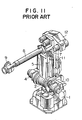
- FIG. 10 A typical example of spot welding robots adopted in vehicle body manufacturing lines is shown in Figures 10 and 11.
- the robot includes a stationary base 1 supporting a swivel body 2 for swivel movements about a vertical axis 3.
- a vertical swing arm 5 On the swivel body 2, there is mounted a vertical swing arm 5 for fore-and-aft swinging movements about a horizontal axis 6.
- a horizontal swing arm 8 On the upper end portion of the arm 5, there is mounted a horizontal swing arm 8 for vertical swing movements about a horizontal axis 7.
- the horizontal arm 8 carries a hand 9 having welding electrodes at a tip end.
- a link 11 is provided to extend in parallel with the arm 5 and connected at an upper end with a rearward end portion of the horizontal arm 8.
- the link 11 has a lower end which is connected with a horizontal link 11a which extends rearwardly from the axis 6 in parallel with the arm 8.
- the swivel body 2 is provided with a driving motor 4 for driving the arm 5 about the axis 6.
- the arm 5 is swingable in the fore-and-aft direction through an angular range ⁇ 2.
- the swivel body 2 is further provided with a driving motor 10 which is arranged to drive the link 11a so that the link 11 is moved in a vertical direction to thereby make the horizontal arm 8 swing in the vertical direction through an angular range ⁇ 3.
- Appropriate operations of the motors 4 and 10 cause swinging movements of the arms 5 and 8 so that the robot hand 9 can be moved in the region designated by the reference numeral 13.
- the rear end portion 14 of the arm 8 moves along a circular path of a radius R1 with a center at the axis 3 when the robot is rotated about the axis 3.
- a plurality of robots 16 are arranged side by side with relatively small spacings between each adjacent two robots as shown in Figure 12 at each side of a conveyor along which vehicle bodies 15 are moved. The aforementioned movement of the rear end portion 14 of the arm 8 may then cause an interference with the adjacent robot so that a larger spacing between each two adjacent robots must be provided for avoiding such possible interference.
- Another object of the present invention is to provide an industrial robot in which possibility of interference with a robot which is located to the first-mentioned robot can significantly be decreased.
- an industrial robot including an arm assembly having at least a first arm and a second arm, each having a longitudinal axis, said first arm being mounted at a lower end portion on a base for a swingable movement in a substantially vertical plane about a substantially horizontal first axis, said second arm being provided adjacent to an upper end portion of said first arm to extend in a direction crossing the longitudinal axis of said first arm, pivot means provided between said first and second arms for allowing swingable movements of said second arm with respect to said first arm about a second axis which is perpendicular to the longitudinal axis of said first arm and a third axis which is in a plane containing the longitudinal axis of said first arm, driving means for selectively effecting said swingable movements of said first and second arms.
- the pivot means is provided for allowing a swingable movement about the third axis which is in a plane containing the longitudinal axis of the first arm and the pivot means is located above the first axis which is provided for the swingable movement of the first arm in a substantially vertical plane.
- the second axis is located below the third axis.
- a swingable member may be connected to the upper end portion of the for the swingable movement about the second axis.
- the second arm is connected to the swingable member for the swingable movement about the third axis.
- the swingable member is swingable in a substantially vertical plane and the third axis lies in this plane.
- the third axis is located below the second axis.
- a rotatable member may be provided in axial alignment with the longitudinal axis of the first arm for a rotational movement about the third axis which is in an axial alignment with the longitudinal axis of the first arm.
- the second arm may then be connected with the rotatable member for the swingable movement about the second axis in a sideward direction.
- a spot welding robot including a stationary base 20 supporting a lower arm 22 for a swingable movement about a horizontal axis 21.
- the lower arm 22 extends upwards from the base 20 and has an upper end on which an upper arm 24 is mounted.
- a swingable member or a mounting bracket 42 For mounting the upper arm 24 on the lower arm 22, there in provided a swingable member or a mounting bracket 42.
- the swingable member 42 has a pair of stub shafts 42a provided at diametrically opposite positions and is mounted at the stub shafts 42a on the upper end portion of the lower arm 22 for swingable movement about a horizontal axis 23.
- a link 39 is provided in parallel with the lower arm 22.
- the lower end of the lower arm 22 is mounted on the base 20 through a horizontal shaft 20a which has an axis coaxial with the aforementioned axis 21.
- a horizontal link 38 is integrally connected at one end with the horizontal shaft 20a.
- the other end of the horizontal link 38 is pivotally connected through a pin 40 with the lower end of the link 39.
- the upper end of the link 39 is pivotally connected through a pin 41 with the swingable member 42 as shown in Figure 1.
- the upper arm 24 is formed at a rear end portion 54 with a stub shaft 54a which is extending vertically downward and mounted through a bearing 54b on the upper end of the lower arm 22 for swingable movement about an axis 26 which is perpendicular to the axis 23.
- the upper arm 24 is provided at a front or tip end with a hand 55 which has welding electrodes.
- the arm In order to drive the lower arm 22 for effecting the swingable movement, the arm is provided at the lower end portion with a gear 43 as shown in Figure 3.
- the gear 43 is in meshing engagement with a gear 80.
- a driving motor 81 is provided and has an output shaft 81a which is drivingly connected through a gear mechanism 82 with the gear 80. A selective operation of the driving motor 81 will therefore produce a swingable movement of the lower arm 22 throughout an angular range ⁇ 11 shown in Figure 1.
- the shaft 20a is provided with a gear 36 which is rigidly secured to the shaft 20a.
- a motor 27 is provided and has an output shaft 28 to which a driving gear 29 is secured.
- an intermediate gear is provided on an intermediate shaft 31 and is in meshing engagement with the driving gear 29.
- the intermediate shaft 31 further has a gear 32 secured thereto.
- the gear 32 on the intermediate shaft 31 is in meshing engagement with a gear 33 provided on a second intermediate shaft 34.
- the second intermediate shaft 34 has a gear 35 which is in meshing engagement with the driving gear 36 on the shaft 20a.
- the lower arm 22, the links 38 and 39 and the swingable member 42 provide a parallelogram so that a selective operation of the driving motor 27 causes a swinging movement of the link 38 and a swinging movement of the member 42.
- the upper arm 24 is swingably moved through an angular range ⁇ 12 as shown in Figure 1.
- a driving motor 25 is provided on a rear end portion of the swingable member 42.
- the motor 25 has an output shaft 46 which is provided with a pulley 46a.
- a pulley 48 which is drivingly connected with the pulley 46a through a belt 47.
- An intermediate pulley 49 is provided coaxially with the pulley 48 and connected with this pulley 48 to rotate together.
- a driven pulley 51 is provided at the lower end portion of the stub shaft 54a on the rear end portion 54 of the upper arm 24 and connected with the pulley 49 through a belt 50.
- the hand 55 on the tip end of the upper arm 24 can be moved throughout the range 56 as shown in Figures 1 and 2 by selective operation of the driving motors 25, 27 and 81.
- the lower arm is moved to swing between a forwardly inclined position 57 and a rearwardly inclined position 58.
- the swing axis 26 is shifted rearwards to a position shown by a reference 26a in Figure 2.
- the rear end portion of the swingable member 42 is also shifted rearwards to a position shown by a reference 42b.
- the motor 25 is operated with the lower arm 22 located in this rearwardly inclined position 58, the rear end portion 54 of the upper arm 24 will be moved along a circular path having a center of the circle at the point 26a as shown by a reference 54b in Figure 2.
- the horizontal swinging movement is produced about a vertical axis which will not be shifted rearward even when the lower arm is inclined rearwards. Therefore, the upper arm 24 will be swingably moved about the axis 26 even when the lower arm is fully inclined rearwards.
- the rear end portion 54 of the upper arm 24 will be moved along a circular path 54c having a center of circle at the point 26 as shown in Figure 2.
- the arrangement of the present invention is advantageous over the conventional design in that the path of the rear end portion 54 of the upper arm 24 is much smaller than in the conventional design.
- the illustrated structure is further advantageous in that the motor 25 for driving the upper arm 24 is provided on the swingable member 42 which is formed separately from the upper arm 24.
- the swingable member 42 will be shifted rearwards to the position shown by 42b when the lower arm 2 is fully inclined rearwards.
- the rear end portion of the member 42 does not move when the upper arm 24 is swung about the axis 26a.
- the upper arm is mounted on the upper end portion of the lower arm and had a rearward extension to provide the aforementioned parallelogram.
- the rear end portion of the upper arm will therefore be moved along a circular path 59 having a center of circle at the point 26 shown in Figure 2.
- the structure of the illustrated arrangement is therefore significantly advantageous over the conventional design in decreasing the space required for locating the robot.
- FIG 8 there is shown a typical example of arranging the robots in accordance with the present invention.
- vehicle bodies 60 to be welded are transported along a conveyor 62.
- a plurality of robots 61 are arranged along the opposite sides of the conveyor 62. According to the present invention, it becomes possible to locate the robots with close spacings.
- the robot shown in Figure 9 includes a stationary base 63 supporting a lower arm 65 through a horizontal shaft 64 for a swingable movement.
- An intermediate arm 67 is connected with the lower arm 65 through a swivel joint 66 so that the arm 67 is rotatable about a longitudinal axis of the lower arm 65.
- An upper arm 68 is connected to an upper end of the intermediate arm 67 for a swingable movement about an axis 71 which is perpendicular to the longitudinal axis of the lower arm 65.
- the upper arm 68 is connected at a tip end with a second upper arm 70 through a swivel joint 69 for rotation about a longitudinal axis of the first upper axis 68.
Landscapes
- Engineering & Computer Science (AREA)
- Physics & Mathematics (AREA)
- Optics & Photonics (AREA)
- Robotics (AREA)
- Mechanical Engineering (AREA)
- Plasma & Fusion (AREA)
- Manipulator (AREA)
Applications Claiming Priority (2)
| Application Number | Priority Date | Filing Date | Title |
|---|---|---|---|
| JP63226157A JPH0832401B2 (ja) | 1988-09-08 | 1988-09-08 | 産業用ロボット |
| JP226157/88 | 1988-09-08 |
Publications (2)
| Publication Number | Publication Date |
|---|---|
| EP0361140A1 true EP0361140A1 (fr) | 1990-04-04 |
| EP0361140B1 EP0361140B1 (fr) | 1999-05-26 |
Family
ID=16840757
Family Applications (1)
| Application Number | Title | Priority Date | Filing Date |
|---|---|---|---|
| EP89116370A Expired - Lifetime EP0361140B1 (fr) | 1988-09-08 | 1989-09-05 | Robot industriel |
Country Status (5)
| Country | Link |
|---|---|
| US (2) | US5145312A (fr) |
| EP (1) | EP0361140B1 (fr) |
| JP (1) | JPH0832401B2 (fr) |
| KR (1) | KR920008818B1 (fr) |
| DE (1) | DE68929004T2 (fr) |
Cited By (6)
| Publication number | Priority date | Publication date | Assignee | Title |
|---|---|---|---|---|
| WO1994025226A1 (fr) * | 1993-04-30 | 1994-11-10 | Asea Brown Boveri Ab | Robot industriel |
| NL1037425C2 (nl) * | 2009-10-29 | 2011-05-02 | Albert Meer | Robot. |
| CN103659798A (zh) * | 2012-08-31 | 2014-03-26 | 精工爱普生株式会社 | 机器人 |
| CN103722553A (zh) * | 2013-12-17 | 2014-04-16 | 广西大学 | 一种多自由度并联机构式可控焊接机器人 |
| CN104589309A (zh) * | 2014-12-12 | 2015-05-06 | 广西大学 | 一种多自由度并联机构式可控移动焊接机器人 |
| CN103659798B (zh) * | 2012-08-31 | 2016-11-30 | 精工爱普生株式会社 | 机器人 |
Families Citing this family (11)
| Publication number | Priority date | Publication date | Assignee | Title |
|---|---|---|---|---|
| JPH0832402B2 (ja) * | 1989-12-28 | 1996-03-29 | 川崎重工業株式会社 | 産業用ロボツト |
| SE515119C2 (sv) * | 1995-03-30 | 2001-06-11 | Abb Ab | Industrirobot |
| US6253458B1 (en) * | 1998-12-08 | 2001-07-03 | Faro Technologies, Inc. | Adjustable counterbalance mechanism for a coordinate measurement machine |
| US6263755B1 (en) | 1999-02-10 | 2001-07-24 | New York University | Robotic manipulator and method |
| SE0001163L (sv) * | 2000-03-31 | 2001-10-01 | Anani Vladimirov Ananiev | Omkonfigurerbar lättviktsrobotarm för mobila robotar |
| EP2243602B1 (fr) * | 2009-04-22 | 2013-05-15 | KUKA Roboter GmbH | Procédé et dispositif de commande d'un manipulateur |
| CN102259337B (zh) * | 2010-05-28 | 2013-11-06 | 鸿富锦精密工业(深圳)有限公司 | 机器人臂部件 |
| CN102275158A (zh) * | 2010-06-10 | 2011-12-14 | 鸿富锦精密工业(深圳)有限公司 | 机器人 |
| CN103406900A (zh) * | 2013-09-03 | 2013-11-27 | 常熟市惠一机电有限公司 | 旋臂式机械手 |
| CN105081633B (zh) * | 2015-07-22 | 2017-05-03 | 北京中电华强焊接工程技术有限公司 | 五自由度焊接切割机器人 |
| CN113829335A (zh) * | 2021-11-29 | 2021-12-24 | 北京精准医械科技有限公司 | 用于狭小作业空间的机械臂 |
Citations (9)
| Publication number | Priority date | Publication date | Assignee | Title |
|---|---|---|---|---|
| GB781465A (en) * | 1954-03-29 | 1957-08-21 | Cyril Walter Kenward | Improvements in or relating to positioning, assembling or manipulating apparatus |
| FR1475018A (fr) * | 1966-02-18 | 1967-03-31 | Commissariat Energie Atomique | Télémanipulateur |
| FR2183584A1 (fr) * | 1972-05-10 | 1973-12-21 | Commissariat Energie Atomique | |
| US4095481A (en) * | 1975-12-19 | 1978-06-20 | Hitachi, Ltd. | Joint mechanism of manipulator |
| US4308584A (en) * | 1978-12-20 | 1981-12-29 | Agency Of Industrial Science & Technology | Apparatus for control of manipulator |
| DE3301022A1 (de) * | 1983-01-14 | 1984-07-26 | Bayerische Motoren Werke AG, 8000 München | Manipulator |
| EP0124824A1 (fr) * | 1983-05-10 | 1984-11-14 | Siemens Aktiengesellschaft | Dispositif de positionnement pour appareil d'inspection, de nettoyage et de réparation d'un ensemble de tubes parallèles |
| US4585387A (en) * | 1983-10-11 | 1986-04-29 | William Jayne | Robot arm |
| US4828453A (en) * | 1987-04-21 | 1989-05-09 | The United States Of America As Represented By The United States Department Of Energy | Modular multimorphic kinematic arm structure and pitch and yaw joint for same |
Family Cites Families (11)
| Publication number | Priority date | Publication date | Assignee | Title |
|---|---|---|---|---|
| JPS57189781A (en) * | 1981-05-19 | 1982-11-22 | Tokyo Shibaura Electric Co | Device for operating remote control manipulator |
| JPS5894980A (ja) * | 1981-11-27 | 1983-06-06 | 株式会社東芝 | マニピユレ−タ装置 |
| FR2519284A1 (fr) * | 1982-01-07 | 1983-07-08 | Bretagne Atel Chantiers | Telemanipulateur |
| JPS6084280U (ja) * | 1983-11-14 | 1985-06-11 | 株式会社神戸製鋼所 | 工業用ロボツト |
| CA1279678C (fr) * | 1986-02-18 | 1991-01-29 | James P. Karlen | Robot industriel avec dispositif d'asservissement |
| JPS62277292A (ja) * | 1986-05-26 | 1987-12-02 | ファナック株式会社 | 垂直多関節形ロボツト |
| JPS6347078A (ja) * | 1986-08-07 | 1988-02-27 | ダイキン工業株式会社 | 産業用ロボツト |
| US4828451A (en) * | 1986-08-07 | 1989-05-09 | Daikin Industries, Ltd. | Industrial robot |
| JPH01103275A (ja) * | 1987-10-13 | 1989-04-20 | Honda Motor Co Ltd | 産業用ロボットの軸構成 |
| US4921393A (en) * | 1988-03-09 | 1990-05-01 | Sri International | Articulatable structure with adjustable end-point compliance |
| JPH0684280A (ja) * | 1992-08-31 | 1994-03-25 | Victor Co Of Japan Ltd | 雑音低減回路 |
-
1988
- 1988-09-08 JP JP63226157A patent/JPH0832401B2/ja not_active Expired - Lifetime
-
1989
- 1989-09-05 DE DE68929004T patent/DE68929004T2/de not_active Expired - Fee Related
- 1989-09-05 EP EP89116370A patent/EP0361140B1/fr not_active Expired - Lifetime
- 1989-09-08 KR KR1019890013053A patent/KR920008818B1/ko not_active Expired
-
1991
- 1991-04-04 US US07/681,404 patent/US5145312A/en not_active Ceased
-
1995
- 1995-08-16 US US08/515,865 patent/USRE35584E/en not_active Expired - Lifetime
Patent Citations (9)
| Publication number | Priority date | Publication date | Assignee | Title |
|---|---|---|---|---|
| GB781465A (en) * | 1954-03-29 | 1957-08-21 | Cyril Walter Kenward | Improvements in or relating to positioning, assembling or manipulating apparatus |
| FR1475018A (fr) * | 1966-02-18 | 1967-03-31 | Commissariat Energie Atomique | Télémanipulateur |
| FR2183584A1 (fr) * | 1972-05-10 | 1973-12-21 | Commissariat Energie Atomique | |
| US4095481A (en) * | 1975-12-19 | 1978-06-20 | Hitachi, Ltd. | Joint mechanism of manipulator |
| US4308584A (en) * | 1978-12-20 | 1981-12-29 | Agency Of Industrial Science & Technology | Apparatus for control of manipulator |
| DE3301022A1 (de) * | 1983-01-14 | 1984-07-26 | Bayerische Motoren Werke AG, 8000 München | Manipulator |
| EP0124824A1 (fr) * | 1983-05-10 | 1984-11-14 | Siemens Aktiengesellschaft | Dispositif de positionnement pour appareil d'inspection, de nettoyage et de réparation d'un ensemble de tubes parallèles |
| US4585387A (en) * | 1983-10-11 | 1986-04-29 | William Jayne | Robot arm |
| US4828453A (en) * | 1987-04-21 | 1989-05-09 | The United States Of America As Represented By The United States Department Of Energy | Modular multimorphic kinematic arm structure and pitch and yaw joint for same |
Non-Patent Citations (1)
| Title |
|---|
| PROCEEDINGS OF THE IEEE INTERNATIONAL CONFERENCE ON ROBOTICS AND AUTOMATION, vol. 2, 1987, pages 1186-1191, IEEE, New York, US; A.H. SONI et al.: "Application of passive robot in spine surgery" * |
Cited By (8)
| Publication number | Priority date | Publication date | Assignee | Title |
|---|---|---|---|---|
| WO1994025226A1 (fr) * | 1993-04-30 | 1994-11-10 | Asea Brown Boveri Ab | Robot industriel |
| US5622084A (en) * | 1993-04-30 | 1997-04-22 | Asea Brown Boveri Ab | Industrial robot |
| NL1037425C2 (nl) * | 2009-10-29 | 2011-05-02 | Albert Meer | Robot. |
| CN103659798A (zh) * | 2012-08-31 | 2014-03-26 | 精工爱普生株式会社 | 机器人 |
| CN103659798B (zh) * | 2012-08-31 | 2016-11-30 | 精工爱普生株式会社 | 机器人 |
| CN103722553A (zh) * | 2013-12-17 | 2014-04-16 | 广西大学 | 一种多自由度并联机构式可控焊接机器人 |
| CN103722553B (zh) * | 2013-12-17 | 2016-06-15 | 广西大学 | 一种多自由度并联机构式可控焊接机器人 |
| CN104589309A (zh) * | 2014-12-12 | 2015-05-06 | 广西大学 | 一种多自由度并联机构式可控移动焊接机器人 |
Also Published As
| Publication number | Publication date |
|---|---|
| EP0361140B1 (fr) | 1999-05-26 |
| US5145312A (en) | 1992-09-08 |
| DE68929004T2 (de) | 1999-09-16 |
| KR900004464A (ko) | 1990-04-12 |
| KR920008818B1 (ko) | 1992-10-09 |
| JPH0832401B2 (ja) | 1996-03-29 |
| JPH0276689A (ja) | 1990-03-16 |
| DE68929004D1 (de) | 1999-07-01 |
| USRE35584E (en) | 1997-08-12 |
Similar Documents
| Publication | Publication Date | Title |
|---|---|---|
| US5145312A (en) | Industrial robot | |
| US5522275A (en) | Industrial robot, particularly for moving pieces from one press to the other in a line of presses | |
| US4538047A (en) | Method of controlling robotic automatic welding apparatus | |
| US4626165A (en) | Industrial robot wrist mechanism | |
| KR0168697B1 (ko) | 산업용 로봇 | |
| US4655675A (en) | Articulated robot | |
| US4842474A (en) | Vertical multi-articulated robot | |
| EP0468061B1 (fr) | Robot industriel du type a bras articule, avec mecanisme d'articulation de commande | |
| CA2034065C (fr) | Robot industriel | |
| JPS6263073A (ja) | 回動ア−ムの関節構造 | |
| EP0647507B1 (fr) | Robot articule | |
| US5622084A (en) | Industrial robot | |
| JPH11156769A (ja) | 双腕型スカラロボット | |
| GB2175874A (en) | Workpiece feeding apparatus in a seam welding machine | |
| EP0121576A1 (fr) | Bras articule pour robot industriel | |
| JP2797421B2 (ja) | ロボットのアーム駆動機構 | |
| JPS59127999A (ja) | ポジシヨナ | |
| JPS6327113B2 (fr) | ||
| JPH06246447A (ja) | 溶接トーチの姿勢制御装置 | |
| JP2001179676A (ja) | エンドエフェクタ用動力伝達装置および方法 | |
| JPS6312753B2 (fr) | ||
| JPH06311B2 (ja) | 産業用ロボツト | |
| KR850002093Y1 (ko) | 관절형 로보트의 손목 구동장치 | |
| KR900001673B1 (ko) | 시임용접기에 있어서의 워크 유도장치 | |
| JPH0730796B2 (ja) | 農業機械用継手 |
Legal Events
| Date | Code | Title | Description |
|---|---|---|---|
| PUAI | Public reference made under article 153(3) epc to a published international application that has entered the european phase |
Free format text: ORIGINAL CODE: 0009012 |
|
| AK | Designated contracting states |
Kind code of ref document: A1 Designated state(s): DE ES FR GB |
|
| 17P | Request for examination filed |
Effective date: 19900622 |
|
| 17Q | First examination report despatched |
Effective date: 19911212 |
|
| APAA | Appeal reference recorded |
Free format text: ORIGINAL CODE: EPIDOS REFN |
|
| APAD | Appeal reference recorded |
Free format text: ORIGINAL CODE: EPIDOS REFNE |
|
| APCB | Communication from the board of appeal sent |
Free format text: ORIGINAL CODE: EPIDOS OBAPE |
|
| APCB | Communication from the board of appeal sent |
Free format text: ORIGINAL CODE: EPIDOS OBAPE |
|
| APCB | Communication from the board of appeal sent |
Free format text: ORIGINAL CODE: EPIDOS OBAPE |
|
| APCB | Communication from the board of appeal sent |
Free format text: ORIGINAL CODE: EPIDOS OBAPE |
|
| APAB | Appeal dossier modified |
Free format text: ORIGINAL CODE: EPIDOS NOAPE |
|
| GRAG | Despatch of communication of intention to grant |
Free format text: ORIGINAL CODE: EPIDOS AGRA |
|
| GRAH | Despatch of communication of intention to grant a patent |
Free format text: ORIGINAL CODE: EPIDOS IGRA |
|
| GRAH | Despatch of communication of intention to grant a patent |
Free format text: ORIGINAL CODE: EPIDOS IGRA |
|
| GRAA | (expected) grant |
Free format text: ORIGINAL CODE: 0009210 |
|
| AK | Designated contracting states |
Kind code of ref document: B1 Designated state(s): DE ES FR GB |
|
| PG25 | Lapsed in a contracting state [announced via postgrant information from national office to epo] |
Ref country code: FR Free format text: LAPSE BECAUSE OF FAILURE TO SUBMIT A TRANSLATION OF THE DESCRIPTION OR TO PAY THE FEE WITHIN THE PRESCRIBED TIME-LIMIT Effective date: 19990526 Ref country code: ES Free format text: THE PATENT HAS BEEN ANNULLED BY A DECISION OF A NATIONAL AUTHORITY Effective date: 19990526 |
|
| REF | Corresponds to: |
Ref document number: 68929004 Country of ref document: DE Date of ref document: 19990701 |
|
| EN | Fr: translation not filed | ||
| PLBE | No opposition filed within time limit |
Free format text: ORIGINAL CODE: 0009261 |
|
| STAA | Information on the status of an ep patent application or granted ep patent |
Free format text: STATUS: NO OPPOSITION FILED WITHIN TIME LIMIT |
|
| 26N | No opposition filed | ||
| REG | Reference to a national code |
Ref country code: GB Ref legal event code: IF02 |
|
| PGFP | Annual fee paid to national office [announced via postgrant information from national office to epo] |
Ref country code: GB Payment date: 20040901 Year of fee payment: 16 |
|
| PGFP | Annual fee paid to national office [announced via postgrant information from national office to epo] |
Ref country code: DE Payment date: 20040902 Year of fee payment: 16 |
|
| PG25 | Lapsed in a contracting state [announced via postgrant information from national office to epo] |
Ref country code: GB Free format text: LAPSE BECAUSE OF NON-PAYMENT OF DUE FEES Effective date: 20050905 |
|
| APAH | Appeal reference modified |
Free format text: ORIGINAL CODE: EPIDOSCREFNO |
|
| PG25 | Lapsed in a contracting state [announced via postgrant information from national office to epo] |
Ref country code: DE Free format text: LAPSE BECAUSE OF NON-PAYMENT OF DUE FEES Effective date: 20060401 |
|
| GBPC | Gb: european patent ceased through non-payment of renewal fee |
Effective date: 20050905 |