EP0362711B1 - Article céramique cuit avec un article métallique - Google Patents
Article céramique cuit avec un article métallique Download PDFInfo
- Publication number
- EP0362711B1 EP0362711B1 EP89118068A EP89118068A EP0362711B1 EP 0362711 B1 EP0362711 B1 EP 0362711B1 EP 89118068 A EP89118068 A EP 89118068A EP 89118068 A EP89118068 A EP 89118068A EP 0362711 B1 EP0362711 B1 EP 0362711B1
- Authority
- EP
- European Patent Office
- Prior art keywords
- point
- cooling
- metallic
- brazing filler
- ceramic
- Prior art date
- Legal status (The legal status is an assumption and is not a legal conclusion. Google has not performed a legal analysis and makes no representation as to the accuracy of the status listed.)
- Expired - Lifetime
Links
- 239000000919 ceramic Substances 0.000 title claims description 56
- 239000000463 material Substances 0.000 claims description 66
- 238000005219 brazing Methods 0.000 claims description 46
- 239000000945 filler Substances 0.000 claims description 38
- 230000009466 transformation Effects 0.000 claims description 37
- 239000007769 metal material Substances 0.000 claims description 36
- 238000005304 joining Methods 0.000 claims description 27
- 229910001562 pearlite Inorganic materials 0.000 claims description 21
- 229910000734 martensite Chemical group 0.000 claims description 20
- 229910001563 bainite Inorganic materials 0.000 claims description 9
- 238000010008 shearing Methods 0.000 claims description 9
- FBPFZTCFMRRESA-JGWLITMVSA-N D-glucitol Chemical group OC[C@H](O)[C@@H](O)[C@H](O)[C@H](O)CO FBPFZTCFMRRESA-JGWLITMVSA-N 0.000 claims description 5
- XEEYBQQBJWHFJM-UHFFFAOYSA-N Iron Chemical compound [Fe] XEEYBQQBJWHFJM-UHFFFAOYSA-N 0.000 claims description 5
- 238000004781 supercooling Methods 0.000 claims description 5
- 229910001566 austenite Inorganic materials 0.000 claims description 2
- 229910052742 iron Inorganic materials 0.000 claims description 2
- 238000001816 cooling Methods 0.000 description 96
- 230000008602 contraction Effects 0.000 description 31
- 238000000034 method Methods 0.000 description 22
- 229910052751 metal Inorganic materials 0.000 description 20
- 239000002184 metal Substances 0.000 description 20
- 239000011572 manganese Substances 0.000 description 14
- PXHVJJICTQNCMI-UHFFFAOYSA-N nickel Substances [Ni] PXHVJJICTQNCMI-UHFFFAOYSA-N 0.000 description 14
- 229910000831 Steel Inorganic materials 0.000 description 13
- 239000010959 steel Substances 0.000 description 13
- 229910052581 Si3N4 Inorganic materials 0.000 description 10
- 229910000975 Carbon steel Inorganic materials 0.000 description 8
- 239000010962 carbon steel Substances 0.000 description 8
- 230000008569 process Effects 0.000 description 8
- 230000000694 effects Effects 0.000 description 7
- 238000010438 heat treatment Methods 0.000 description 7
- 239000003921 oil Substances 0.000 description 7
- XLYOFNOQVPJJNP-UHFFFAOYSA-N water Substances O XLYOFNOQVPJJNP-UHFFFAOYSA-N 0.000 description 7
- 230000000052 comparative effect Effects 0.000 description 6
- 230000002349 favourable effect Effects 0.000 description 5
- PNEYBMLMFCGWSK-UHFFFAOYSA-N aluminium oxide Inorganic materials [O-2].[O-2].[O-2].[Al+3].[Al+3] PNEYBMLMFCGWSK-UHFFFAOYSA-N 0.000 description 4
- 229910010293 ceramic material Inorganic materials 0.000 description 4
- 238000005336 cracking Methods 0.000 description 4
- 238000006073 displacement reaction Methods 0.000 description 4
- 229910052748 manganese Inorganic materials 0.000 description 4
- 229910052759 nickel Inorganic materials 0.000 description 4
- HQVNEWCFYHHQES-UHFFFAOYSA-N silicon nitride Chemical compound N12[Si]34N5[Si]62N3[Si]51N64 HQVNEWCFYHHQES-UHFFFAOYSA-N 0.000 description 4
- 238000005275 alloying Methods 0.000 description 3
- 229910052799 carbon Inorganic materials 0.000 description 3
- 238000002844 melting Methods 0.000 description 3
- 150000002739 metals Chemical class 0.000 description 3
- 239000000203 mixture Substances 0.000 description 3
- 229910052750 molybdenum Inorganic materials 0.000 description 3
- 230000002093 peripheral effect Effects 0.000 description 3
- 230000009467 reduction Effects 0.000 description 3
- HBMJWWWQQXIZIP-UHFFFAOYSA-N silicon carbide Chemical compound [Si+]#[C-] HBMJWWWQQXIZIP-UHFFFAOYSA-N 0.000 description 3
- 229910010271 silicon carbide Inorganic materials 0.000 description 3
- 229910000679 solder Inorganic materials 0.000 description 3
- XKRFYHLGVUSROY-UHFFFAOYSA-N Argon Chemical compound [Ar] XKRFYHLGVUSROY-UHFFFAOYSA-N 0.000 description 2
- IJGRMHOSHXDMSA-UHFFFAOYSA-N Atomic nitrogen Chemical compound N#N IJGRMHOSHXDMSA-UHFFFAOYSA-N 0.000 description 2
- 229910000914 Mn alloy Inorganic materials 0.000 description 2
- 229910052804 chromium Inorganic materials 0.000 description 2
- 238000010586 diagram Methods 0.000 description 2
- 239000011261 inert gas Substances 0.000 description 2
- 230000005764 inhibitory process Effects 0.000 description 2
- 230000013011 mating Effects 0.000 description 2
- 238000005240 physical vapour deposition Methods 0.000 description 2
- 102200082816 rs34868397 Human genes 0.000 description 2
- 238000005245 sintering Methods 0.000 description 2
- 238000005476 soldering Methods 0.000 description 2
- 230000035882 stress Effects 0.000 description 2
- RUDFQVOCFDJEEF-UHFFFAOYSA-N yttrium(III) oxide Inorganic materials [O-2].[O-2].[O-2].[Y+3].[Y+3] RUDFQVOCFDJEEF-UHFFFAOYSA-N 0.000 description 2
- 229910017083 AlN Inorganic materials 0.000 description 1
- PIGFYZPCRLYGLF-UHFFFAOYSA-N Aluminum nitride Chemical compound [Al]#N PIGFYZPCRLYGLF-UHFFFAOYSA-N 0.000 description 1
- 229910001030 Iron–nickel alloy Inorganic materials 0.000 description 1
- PWHULOQIROXLJO-UHFFFAOYSA-N Manganese Chemical compound [Mn] PWHULOQIROXLJO-UHFFFAOYSA-N 0.000 description 1
- 229910000990 Ni alloy Inorganic materials 0.000 description 1
- 229910001069 Ti alloy Inorganic materials 0.000 description 1
- URQWOSCGQKPJCM-UHFFFAOYSA-N [Mn].[Fe].[Ni] Chemical compound [Mn].[Fe].[Ni] URQWOSCGQKPJCM-UHFFFAOYSA-N 0.000 description 1
- 230000002159 abnormal effect Effects 0.000 description 1
- 229910045601 alloy Inorganic materials 0.000 description 1
- 239000000956 alloy Substances 0.000 description 1
- 229910052786 argon Inorganic materials 0.000 description 1
- 230000008859 change Effects 0.000 description 1
- 238000002485 combustion reaction Methods 0.000 description 1
- 239000002131 composite material Substances 0.000 description 1
- 239000002826 coolant Substances 0.000 description 1
- 239000000112 cooling gas Substances 0.000 description 1
- PMHQVHHXPFUNSP-UHFFFAOYSA-M copper(1+);methylsulfanylmethane;bromide Chemical compound Br[Cu].CSC PMHQVHHXPFUNSP-UHFFFAOYSA-M 0.000 description 1
- 229910052593 corundum Inorganic materials 0.000 description 1
- 230000001186 cumulative effect Effects 0.000 description 1
- 239000007772 electrode material Substances 0.000 description 1
- 239000007789 gas Substances 0.000 description 1
- 230000006872 improvement Effects 0.000 description 1
- DALUDRGQOYMVLD-UHFFFAOYSA-N iron manganese Chemical compound [Mn].[Fe] DALUDRGQOYMVLD-UHFFFAOYSA-N 0.000 description 1
- 229910000833 kovar Inorganic materials 0.000 description 1
- 239000007788 liquid Substances 0.000 description 1
- 238000003754 machining Methods 0.000 description 1
- 238000005259 measurement Methods 0.000 description 1
- 230000008018 melting Effects 0.000 description 1
- 229910003465 moissanite Inorganic materials 0.000 description 1
- 229910052757 nitrogen Inorganic materials 0.000 description 1
- 229910052698 phosphorus Inorganic materials 0.000 description 1
- 238000010791 quenching Methods 0.000 description 1
- 230000000171 quenching effect Effects 0.000 description 1
- 230000035939 shock Effects 0.000 description 1
- -1 sialon Inorganic materials 0.000 description 1
- 229910052710 silicon Inorganic materials 0.000 description 1
- 238000007711 solidification Methods 0.000 description 1
- 230000008023 solidification Effects 0.000 description 1
- 238000004544 sputter deposition Methods 0.000 description 1
- 230000008646 thermal stress Effects 0.000 description 1
- 229910052721 tungsten Inorganic materials 0.000 description 1
- 229910052720 vanadium Inorganic materials 0.000 description 1
- 238000003466 welding Methods 0.000 description 1
- 229910001845 yogo sapphire Inorganic materials 0.000 description 1
Images
Classifications
-
- C—CHEMISTRY; METALLURGY
- C04—CEMENTS; CONCRETE; ARTIFICIAL STONE; CERAMICS; REFRACTORIES
- C04B—LIME, MAGNESIA; SLAG; CEMENTS; COMPOSITIONS THEREOF, e.g. MORTARS, CONCRETE OR LIKE BUILDING MATERIALS; ARTIFICIAL STONE; CERAMICS; REFRACTORIES; TREATMENT OF NATURAL STONE
- C04B37/00—Joining burned ceramic articles with other burned ceramic articles or other articles by heating
- C04B37/02—Joining burned ceramic articles with other burned ceramic articles or other articles by heating with metallic articles
- C04B37/023—Joining burned ceramic articles with other burned ceramic articles or other articles by heating with metallic articles characterised by the interlayer used
- C04B37/026—Joining burned ceramic articles with other burned ceramic articles or other articles by heating with metallic articles characterised by the interlayer used consisting of metals or metal salts
-
- C—CHEMISTRY; METALLURGY
- C04—CEMENTS; CONCRETE; ARTIFICIAL STONE; CERAMICS; REFRACTORIES
- C04B—LIME, MAGNESIA; SLAG; CEMENTS; COMPOSITIONS THEREOF, e.g. MORTARS, CONCRETE OR LIKE BUILDING MATERIALS; ARTIFICIAL STONE; CERAMICS; REFRACTORIES; TREATMENT OF NATURAL STONE
- C04B2235/00—Aspects relating to ceramic starting mixtures or sintered ceramic products
- C04B2235/65—Aspects relating to heat treatments of ceramic bodies such as green ceramics or pre-sintered ceramics, e.g. burning, sintering or melting processes
- C04B2235/656—Aspects relating to heat treatments of ceramic bodies such as green ceramics or pre-sintered ceramics, e.g. burning, sintering or melting processes characterised by specific heating conditions during heat treatment
- C04B2235/6565—Cooling rate
-
- C—CHEMISTRY; METALLURGY
- C04—CEMENTS; CONCRETE; ARTIFICIAL STONE; CERAMICS; REFRACTORIES
- C04B—LIME, MAGNESIA; SLAG; CEMENTS; COMPOSITIONS THEREOF, e.g. MORTARS, CONCRETE OR LIKE BUILDING MATERIALS; ARTIFICIAL STONE; CERAMICS; REFRACTORIES; TREATMENT OF NATURAL STONE
- C04B2237/00—Aspects relating to ceramic laminates or to joining of ceramic articles with other articles by heating
- C04B2237/02—Aspects relating to interlayers, e.g. used to join ceramic articles with other articles by heating
- C04B2237/12—Metallic interlayers
- C04B2237/122—Metallic interlayers based on refractory metals
-
- C—CHEMISTRY; METALLURGY
- C04—CEMENTS; CONCRETE; ARTIFICIAL STONE; CERAMICS; REFRACTORIES
- C04B—LIME, MAGNESIA; SLAG; CEMENTS; COMPOSITIONS THEREOF, e.g. MORTARS, CONCRETE OR LIKE BUILDING MATERIALS; ARTIFICIAL STONE; CERAMICS; REFRACTORIES; TREATMENT OF NATURAL STONE
- C04B2237/00—Aspects relating to ceramic laminates or to joining of ceramic articles with other articles by heating
- C04B2237/02—Aspects relating to interlayers, e.g. used to join ceramic articles with other articles by heating
- C04B2237/12—Metallic interlayers
- C04B2237/125—Metallic interlayers based on noble metals, e.g. silver
-
- C—CHEMISTRY; METALLURGY
- C04—CEMENTS; CONCRETE; ARTIFICIAL STONE; CERAMICS; REFRACTORIES
- C04B—LIME, MAGNESIA; SLAG; CEMENTS; COMPOSITIONS THEREOF, e.g. MORTARS, CONCRETE OR LIKE BUILDING MATERIALS; ARTIFICIAL STONE; CERAMICS; REFRACTORIES; TREATMENT OF NATURAL STONE
- C04B2237/00—Aspects relating to ceramic laminates or to joining of ceramic articles with other articles by heating
- C04B2237/02—Aspects relating to interlayers, e.g. used to join ceramic articles with other articles by heating
- C04B2237/12—Metallic interlayers
- C04B2237/126—Metallic interlayers wherein the active component for bonding is not the largest fraction of the interlayer
- C04B2237/127—The active component for bonding being a refractory metal
-
- C—CHEMISTRY; METALLURGY
- C04—CEMENTS; CONCRETE; ARTIFICIAL STONE; CERAMICS; REFRACTORIES
- C04B—LIME, MAGNESIA; SLAG; CEMENTS; COMPOSITIONS THEREOF, e.g. MORTARS, CONCRETE OR LIKE BUILDING MATERIALS; ARTIFICIAL STONE; CERAMICS; REFRACTORIES; TREATMENT OF NATURAL STONE
- C04B2237/00—Aspects relating to ceramic laminates or to joining of ceramic articles with other articles by heating
- C04B2237/30—Composition of layers of ceramic laminates or of ceramic or metallic articles to be joined by heating, e.g. Si substrates
- C04B2237/32—Ceramic
- C04B2237/36—Non-oxidic
- C04B2237/365—Silicon carbide
-
- C—CHEMISTRY; METALLURGY
- C04—CEMENTS; CONCRETE; ARTIFICIAL STONE; CERAMICS; REFRACTORIES
- C04B—LIME, MAGNESIA; SLAG; CEMENTS; COMPOSITIONS THEREOF, e.g. MORTARS, CONCRETE OR LIKE BUILDING MATERIALS; ARTIFICIAL STONE; CERAMICS; REFRACTORIES; TREATMENT OF NATURAL STONE
- C04B2237/00—Aspects relating to ceramic laminates or to joining of ceramic articles with other articles by heating
- C04B2237/30—Composition of layers of ceramic laminates or of ceramic or metallic articles to be joined by heating, e.g. Si substrates
- C04B2237/32—Ceramic
- C04B2237/36—Non-oxidic
- C04B2237/366—Aluminium nitride
-
- C—CHEMISTRY; METALLURGY
- C04—CEMENTS; CONCRETE; ARTIFICIAL STONE; CERAMICS; REFRACTORIES
- C04B—LIME, MAGNESIA; SLAG; CEMENTS; COMPOSITIONS THEREOF, e.g. MORTARS, CONCRETE OR LIKE BUILDING MATERIALS; ARTIFICIAL STONE; CERAMICS; REFRACTORIES; TREATMENT OF NATURAL STONE
- C04B2237/00—Aspects relating to ceramic laminates or to joining of ceramic articles with other articles by heating
- C04B2237/30—Composition of layers of ceramic laminates or of ceramic or metallic articles to be joined by heating, e.g. Si substrates
- C04B2237/40—Metallic
- C04B2237/405—Iron metal group, e.g. Co or Ni
- C04B2237/406—Iron, e.g. steel
-
- C—CHEMISTRY; METALLURGY
- C04—CEMENTS; CONCRETE; ARTIFICIAL STONE; CERAMICS; REFRACTORIES
- C04B—LIME, MAGNESIA; SLAG; CEMENTS; COMPOSITIONS THEREOF, e.g. MORTARS, CONCRETE OR LIKE BUILDING MATERIALS; ARTIFICIAL STONE; CERAMICS; REFRACTORIES; TREATMENT OF NATURAL STONE
- C04B2237/00—Aspects relating to ceramic laminates or to joining of ceramic articles with other articles by heating
- C04B2237/50—Processing aspects relating to ceramic laminates or to the joining of ceramic articles with other articles by heating
- C04B2237/70—Forming laminates or joined articles comprising layers of a specific, unusual thickness
- C04B2237/704—Forming laminates or joined articles comprising layers of a specific, unusual thickness of one or more of the ceramic layers or articles
Definitions
- This invention relates to a joined body of a ceramic member and a metallic member.
- the joined body according to this invention is applicable to not only sliding component parts such as tappets, rocker arms, valve bridges, etc., in internal-combustion engines, but also a variety of tools employing brazing (tools comprising a super hard material, an Si3N4 material, etc.), vacuum switches, surge arresters, thyristors, vacuum-sealed terminals, IC packages electrode material, and joined parts with a difference in expansion characteristic,etc.
- Connection of a metallic material and a ceramic material is generally carried out by thermal joining using a brazing filler material.
- Ceramics comprising Si3N4, SiC or the like, however, have coefficients of expansion or contraction equivalent to 1/3 to 1/4 times those of metals. It is difficult to achieve normal joining of such a ceramic and a metal, because a strain is generated in the ceramic due to the difference in contraction coefficient between the ceramic and the metal at the time of contraction in a joining process. Therefore, joining of a ceramic member and a metallic member has hitherto been conducted with stress relaxation by disposing a Cu or other soft metal plate (shock-absorbing plate) between the ceramic member and the metallic member.
- the shock-absorbing plate is required in addition to a brazing filler material, in order to absorb the difference in expantion or contraction between the ceramic member and the metallic member. If the diameter of the joint is too large, the use of the shock-absorbing plate is not enough to absorb the difference in contraction.
- This method thus involves limitation or difficulties in application to joining of a ceramic member and a metallic member with a large joint diameter.
- the conventional joining method requiring the shock-absorbing plate for joning is disadvantageous on an economical basis, involves troublesome setting of members, and has a possibility of the shock-absorbing plate being left unset.
- a direct joining method without using any shock-absorbing plate may be contemplated, in which a metallic material to be joined may be the 42 nickel alloy, Kovar or the like having a relatively low coefficient of expansion. These low-expantion metals, however, generally have an inflection point at a temperature of around 250 to 450°C, at which the expansion coefficient is rapidly increased. Thus, it is difficult to apply the direct joining method and the low-expansion metals to low-expansion ceramics such as silicon nitride, silicon carbide and aluminum nitride. In the case of joining such a low-expansion metal to alumina, there is the problem of high material cost because the low-expasion metal contains expensive Co or Ni in a large amount. Accordingly, there has been a keen request for the development of a directly joined body of a ceramic member and a metallic member, having little joint strain and being inexpensive, as well as a joining method for obtaining the joined body.
- a process for soldering a ceramic member with a metallic member wherein a solder material is interposed between the ceramic member and the metallic member, whereafter said members and the solder material are heated to a temperature higher than the melting point of the solder material.
- the metallic material is preferably selected from iron-nickel alloy, iron-nickel-manganese alloy, or iron-manganese alloy containing nickel and/or manganese in suitable amounts.
- the above object is achieved by the subject matter of claim 1 which defines a body comprising a ceramic member and a metallic member joined by a brazing filler material layer.
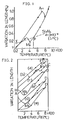
- T °C is the temperature at which a brazing filler material starts to have strength
- curve (a) is a hysteresis curve obtained when the steel is heated from normal temperature and then slowly cooled, which shows contraction associated with the austenitic transformation at point B and re-expansion starting at point C.
- point E pearlite transformation point Ar1
- point F shows contraction from point F, before returned to normal temperature.
- curve (b) When the heated eutectoid steel is air cooled from point D, curve (b) is obtained in which the pearlite transformation point is lower than that in curve (a), due to an increased extent of supercooling.
- the structure obtained in the case of curve (b) is sorbite.
- Curve (d) shows the case where water cooling, which gives a more higher cooling rate, is carried out from point D.
- the pearlite transformation is completly inhibited, and only the martensitic transformation occurs, usually resulting in a mixed structure of bainite and martensite.
- Curve (e) shows the case where the martensitic transformation in curve (d) is inhibited. In this case, ordinarily, a bainite structure is obtained.
- this invention is applicable to a eutectoid steel, even with a cooling rate approximate to the cooling rate of air cooling, as shown by curve (b).
- especial air cooling means the use of an especial air medium cooling method, for instance, introduction of a cooling gas, so as to provide a cooling rate approximate to the cooling rate of oil cooling or water cooling.
- this invention is capable of being applied to the eutectiod steel by raising the cooling rate.
- the brazing filler material layer comprises a brazing filler material having a solidus point not higher than 700°C
- the metallic member comprises a metallic material selected from a group of materials consisting of (1) materials in which the pearlite transformation is inhibited and (2) materials in which the pearlite transformation, including the ordinary pearlite transformation (Ar1) and the supercooled pearlite transformation (Ar') caused by a temperature lower than the ordinary pearlite transformation (Ar1) point after supercooling of austenite, occurs at a temperature not higher than the solidus point of the brazing filler material, said metallic member comprising by weight 1 to 5% of Ni, not more than 8% of Cr, 0.3 to 1.5% of Mn, not more than 1.5% of Mo, not more than 2% of C, and iron, wherein the structure of the metalllic member after joining is a supercooled structure and comprises at least one of the troostite structure, a bainite structure, a sorbite structure and a martensite structure.
- This invention has the following advantages.
- the joined body of a ceramic member and a metallic member according to the prior art utilizes a deformation of a shock-absorbing plate to relieve the difference in displacement due to expansion or contraction between ceramic member and the metallic member
- the joined body according to the first aspect of the invention utilizes a hysteretic property of the metallic material to reduce the difference in displacement due to contracion between the ceramic member and the metallic member. Therefore, the joined body according to the invention has only an extremely slight joint strain and has a favorable joint condition irrespective of the diameter of joint. Further, since there is no need for a shock-absorbing plate, the joined body according to the invention enables a reduction in cost.
- the gist of this invention is to obtain a joined body of ceramic and metal with extremely little joint strain by causing the contraction coefficients of the ceramic and metal upon thermal brazing to be approximately equal to each other through utilization of the abovementioned hysteretic property.
- the joined body according to the invention is characterized by the features (limitations) of claim 1.
- the metallic structure upon joining is at least one of a supercooled structure and a martensite structure.
- the expression "supercooled structure” excludes the pearlite structure in a narrow sense, and includes sorbite, troostite and bainite structures.
- the brazing filler material to be used has a solidus point of not higher than 700°C.
- solidus point used herein means the temperature at which a liquid brazing filler material is completely solidified. The reason for the setting of the solidus point to be not higher than 700 °C will be explained below, referring to Fig. 1.
- a brazing filler material begins to practically have strength at a temperature of about [solidus point - 100°C].
- BAg 8 solidus point 779°C shown in Comparative Example 3
- the material is considered to start showing strength at about 680 °C.
- a normal joined body is not obtainable, and the joint strength obtained is extremely low. Namely, if the temperature at which the brazing filler material starts solidification after the brazing of ceramic and metal to each other is high, even a considerably great hysteresis loop may fail to cover up the difference in contraction between the ceramic and metal. Thus, a lower solidus point is more favorable.
- the solidus point of the brazing filler material is not higher than 70°C, it is possible to obtain a sufficiently high joint strength, even for a large joint diameter.
- This solidus point is generally not lower than 500°C. Because it may be to obtain a sufficiently high joint strength, when the solidus point is lower than 500 °C.
- the metallic material in this invention may be any metallic material capable of a reduction in the difference in cotraction coefficient between the metallic material and a ceramic by lowering the contraction coefficient of the metallic material at a temperature not higher than the temperature at which the brazing filler material starts to show strength. It is desirable that the Ar1 point of the metallic material be not higher than [(solidus point of brazing filler material)- 100°C]. The intended result is satiafactorily attainable when the above-mentioned effect on the cotraction coefficient is provided at a temperature not higher than the temperature at which the brazing filler material starts to have strength (practically, the temperature at which adhesion is started).
- the metallic material a metallic material showing a great hysteresis even with a relatively low cooling rate, around the cooling rate of air cooling.
- the relationship between cooling rate and hysteresis is heavily affected by alloying elements such as Ni, Cr, Mo and Mn.
- alloying elements such as Ni, Cr, Mo and Mn.
- the contents of the alloying elements are important for obtaining a stable hysteresis, even in the presence of such a large cooling rate difference.
- Nickel (Ni) has excellent properties for lowering the transformation point, reducing the mass effect preventing toughness from being lowered due to unsatisfactory quenching etc.
- the content of Ni is preferably 1 to 5 % by weight, and a content of about 3 % by weight is particulary suitablein consideration of productivity and cost.
- the elements Cr, Mo and Mn each have a high effect of lowering the critical cooling rate.
- the Cr content is preferably not more than 8% by weigh, from the viewpoint of balance of cost and the effect.
- Both Mo and Mn have a conspicuous effect on the reduction in the critical cooling rate, even when the amount thereof is small.
- An addition of Mn in an amount of, for example, 0.7% by weight ensures a stable hysteresis, from an outer to a central region of the joined portion, even when the joint diameter is enlarged by a factor of about 3.9.
- the Mn content is preferably 0.3 to 1.5% by weight.
- an addition of Mo in an amount of about 0.2% by weight allows for an incease in the joint diameter by a factor of about 1.6, and the Mo content is preferably not more than 1.5% by weight, similarly to Mn.
- the content of C is preferably not more than about 2% by weight.
- Si, W, V, P or the like may be added in an amount of not more than about 1% by weight, for control of stability of performance.
- S may be added in an amount of not more than 0.1% by weight, for improvement of machining property.
- the cooling condition should be selected so as to reduce strain upon joining, in consideration of the brazing filler material (solidus point ) used, the expansion coefficient of the ceramic, etc.
- the metallic material may be a metallic material which, as indicated by curve (b) in Fig,2, has a higher degree of supercooling and a further lower Ar1 point ( desirably with a further greater hysteresis), as compared with of curve (a), and which has a sorbite structure instead of a pearlite structure after joining ( normal temperature).
- the metallic material may also be a metallic material which, as indicated by curve (c), does not have a clear Ar1 point but has an Ar′ point and which has a troostite structure.
- the metallic material may further be a metallic material which is cooled at a further increased cooling rate as indicated by curve (d) or is perfectly inhibited from pearlite transformation as shown in Fig.1, and is brought into martensitic transformation at a further lower temperature (Ms point) to have a mixed structure of bainite and martensite.
- the metallic material may be a metallic material not brought into martensitic transformation, as indicated by curve (e) in Fig.2.
- the metallic material not undergone the martensitic trasformation is obtainable generally by a method wherein the material is rapidly cooled to a temperature slightly above the martensitic transformation point and is maintained at that temperature.
- the metallic material having the mixed structure of bainite and martensite generally, has a volume greater than the original volume therof due to a volume expansion, as indicated by curve (d).
- the cooling is achievable by an especial gaseous medium cooling method (for instance, by introduction of an appropriate quantity of coolant) which has a cooling rate around the cooling rate of oil cooling or water cooling.
- the cooling is also achievable by oil cooling or water cooling, with some measure to prevent the ceramic from being cracked upon oil cooling and water cooling.
- the cooling means is not particularly limited in the first aspect of this invention.
- the ceramic material in the invention may be Si3N4, sialon, SiC, A l N or a low-expansion low-temperature-fired ceramic (having a coefficient of thermal expansion or contraction of about 2 x 10 ⁇ 6 to 5 x 10 ⁇ 6/ °C, or may be a ceramic having a relatively high coefficient of expansion (7 to 8 x 10 ⁇ 6), such as Al2O3 , or the like.
- the ceramic having a relatively high coefficient of expansion has been considered to be difficult to apply to a large joint diameter (for instance, 10mm ⁇ ), because an increase in joint diameter leads to concentration of cumulative strain on an outer peripheral portion even if the different in contraction between the ceramic and the mating metal is small.
- the ceramic having a relatively high expansion coefficient are favorably applicable to large joint diameters.
- the coefficient of contraction of the metal is the value calculated from the difference between a size at 500 °C and the corresponding size at normal temperature in the cooling process, regardless of the displacements at the intermediate stages of the process.
- the coefficient of contraction is independent also of the size before heating.
- the means for joining for the ceramic member and the metallic member may be a generally known method, such as an activated metal method, a physical vapor deposition method, and a high-melting metal method, provided that the method employs brazing by a brazing filler material having a solidus point of not higher than 700°C.
- gaseous medium cooling means cooling by use of a gas such as air, an inert gas, etc., as a medium, or cooling under a predetermined vacuum.
- the cooling method employed in the joining process is limited to the gaseous medium cooling method, and does not include oil cooling or air cooling. This limitation is provided for securely preventing the cracking of the ceramic, and for ensuring a simple and easy process.
- the metallic material applicable to the joining process of the second aspect of the invention excludes the materials with which the intended result is obtainable by a method other than the gaseous medium cooling, though the magnitude of the cooling rate is not particularly limited. If the cooling rate is less than 0.1°C/sec, it may be difficult to maintain a satisfactory supercooled codition, and such a cooling rate is impractical. On the other hand, a cooling rate of more than 200 °C/sec is too rapid to obtain a stable cooled codition, and is not practical.
- the expression "at least in the vicinity of the A1 point" is used herein because the cooling rate in the vicinity of the A1 point has a great effect on the hysteresis curve.
- the cooling rate in other regions than the vicinity of the A1 point is not particularly limited.
- the "vicinity" of the A1 point generally means the range of the A1 point plus or minus about 100 °C ( more generally, plus or minus about 50°C).
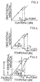
- Fig. 1 The relationship between temperature and elongation (contraction) of a metallic member and a ceramic member used in this examples are shown in Fig. 1 .
- An In-Cu-Ag-Ti alloy was used as the brazing filler material.
- the ceramic member, metallic member and brazing filler material disposed in position were maintained in a vavuum at 790 °C for 15 minutes, cooled (by furnace cooling) to 300 °C over 10 minutes, and then appropriately cooled substantially to room temperrature, to obtain a joined body.
- composition of "SNCM 630" comprised 0.25 to 0.35% by weight of C ("by weight” will be hereinafter referred as "%"), 0.15 to 0.35% of Si, 0.35 to 0.60% of Mn, 2.5 to 3.5% of Ni, 2.5 to 3.5% of Cr, 0.5 to 0.7% of Mo, not more than 0.03% of S, not more than 0.3% of Cu, and not more than 0.03% of P.
- the brazing filler material had a solidus point of 625 °C, and the composition thereof comprised 27% of Cu, 9.5% of In, 1.25% of Ti, and the balance of Ag.
- the "SNCM 630" is an extremely useful material which is inhibited from pearlite transformation by being supercooled even with a relatively low cooling rate around the cooling rate of air cooling, therefore shows a great hysteresis, is easily brought into martensitic transformation even by air cooling, and shows a large hysteresis even under furnace cooling.
- air cooling means a cooling at a cooling rate of not more than about 10 °C/sec, which may be achieved by opening a furnace window to permit a natural flow of the air at room temperature into the furnace, or by introducing an inertgas such as nitrogen and argon through a furnace window into the furnace and operating a fan for forced cooling.
- furnace cooling means a cooling in a furnace, without any artificial change in the furnace, and with a cooling rate lower than the cooling rate of the air cooling. The coolig rate of not higher than 10 °C/sec is attained by air cooling or furnace cooling. Therefore the operation is easy and a satisfactory supercooled condition is maintained.
- the brazing filler material used has a solidus point of 625°C, but the temperature at which the material begins to practically show strength is around 500 °C (point P), which is lower than the solidus point by about 100°C.
- point P 500 °C
- the ceramic member undergoes a contraction of P ⁇ X
- the metallic member undergoes a contraction of P ⁇ Y.
- a difference in contraction of X-Y is left between the ceramic member and the metallic member.
- Such a level of contraction difference does not matter at all, in practical use.
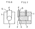
- the joined body returned to room temperature was free of abnormal conditions such as cracks and that the joined body showed a favorable shearing strength of 15kg/ mm2, as measured by use of predetermined jigs, shown in Figs 6 and 7, and a predetermined autograph with a loading rate of 0.5mm/min.
- the shearing strength value was higher than the shearing strength (13kg/ mm2) of a test piece ( Comparative Example 1) obtained through brazing by use of a Cu shock-absorbing plate 0.5 mm thick as well as the same brazing filler material as above.
- the metallic structure in the joined body was comprised mainly martensite.
- Examples 2 to 5 and Comparative Examples 2 and 3 were performed by carrying out the joining of a ceramic member and metallic member, without use of any shock-absorbing plate, while employing the ceramic material, metallic material, brazing filler material, solidus thereof, brazing temperrature and cooling conditions as setforth in Table.
- the metallic materials used in Examples 2 to 4 each have a characteristic curve substantially equivalent to the characteristic curve of Example 1 shown Fig. 1.
- the cooling conditions were so selected as to inhibit the martensitic transformation.
- a disk of 35 mm diameter and 4 mm thickness was used.
- a metal such as Ti was deposited by physical vapor deposition such as sputtering.
- the metallic member a shaft of 35 mm diameter and 50 mm thickness was used.
- silicon nitride A a total of 10 % by weight (hereinafter referred to as "%") of alumina and yttria was uses as a sintering assistant.
- silicon nitride B a total of 10% of aluminium nitride, alumina and yttria was used as a sintering assistant.
- the alloy compositions (%) of the metallic material ( exclusive of the above-mentioned metallic material) and the brazing filler materials used are set forth below.
- SNCM 616 contains 0.16% of C, 1.0% of Mn, 3.0% of Ni, 1.6% of Cr, and 0.5% of Mo;
- SNCM 439 contains 0.39% of C, 0.75% of Mn, 1.8 % of Ni, 0.8% of Cr, and 0.23% of Mo;
- SNCM 815" contains 0.15% of C, 0.45% of Mn, 4.2 5% of Ni, 0.85% of Cr, and 0.23% of Mo;
- S45C contains 0.45% of C;
- “Incusil-15” (a product by GTE PRODUCTS CORPORATION) as the brazing filler material contains 61.5% of Ag, 24% of Cu, and 14.5% of In;
- BAg 5" according to the AWS (American Welding Society) Classification contains 45% of Ag, 30% of Cu, and 25% of Zn;
- BAg 7 contains 56% of Ag, 22% of Cu, and 17% of Zn;
- BAISi-2 contains 7.5% of Si, 0.25% of Cu, 0.
- the metallic structure in the joined body obtained in each of Examples 2 to 4 comprised martensite and bainite, whereas the metallic structure in the joined body obtained in Examples 5 consisted essentially of bainite due to the substantial inhibition of the martensitic transformation.
- the shearing strength of the joined bodies obtained as above was determined by the same method as in Example 1, the results being shown in Table. As seen from the results, in each of Examples 2 to 5 the shearing strength was as high as 14 to 16kg/ mm2, and extremely favorable joining was achieved for the large joint diameter of 35 mm.
- Comparative Example 2 On the other hand, cracking occurred in the ceramic. The reason is as follows. Since the metallic material "S45C" used does not show a great hysteresis through supercooling, as contrasted to the above-mentioned materials, a large difference in contraction results btween the metallic member and the ceramic member. In addition, the large joint diameter of 35mm was employed. Therefore, a heavy strain was generated upon joining, resulting in cracking of the ceramic. Comparative Example 3, in which the brazing filler materials had a high solidus point of more than 700 °C, gave a low shearing strength.
Landscapes
- Chemical & Material Sciences (AREA)
- Engineering & Computer Science (AREA)
- Ceramic Engineering (AREA)
- Materials Engineering (AREA)
- Structural Engineering (AREA)
- Organic Chemistry (AREA)
- Ceramic Products (AREA)
- Heat Treatment Of Articles (AREA)
Claims (4)
- Corps comprenant un élément céramique et un élément métallique assemblés par une couche de matière d'apport de brasage, dans lequel :
la couche de matière d'apport de brasage comprend une matière d'apport de brasage dont le point de solidus ne dépasse pas 700°C, et l'élément métallique comprend une matière métallique choisi dans un groupe composé de (1) une matière dont la transformation en perlite est inhibée et (2) une matière dont la transformation en perlite, y compris la transformation en perlite ordinaire (Ar₁) et la transformation en perlite surfondue (Ar') provoquée par une température inférieure au point de transformation en perlite ordinaire (Ar₁) après la surfusion de l'austénite, est provoquée à une température ne dépassant pas le point de solidus de la matière d'apport de brasage, ledit élément métallique comprenant un poids 1 à 5% de Ni, pas plus de 8% de Cr, 0,3 à 1,5 % de Mn, pas plus de 1,5% de Mo, pas plus de 2% de C, et du fer, dans lequel la structure de l'élément métallique après assemblage est une structure surfondue, et comprend au moins une structure parmi une structure de troostite, une structure de bainite, une structure de sorbite, et une structure de martensite. - Corps selon la revendication 1, dans lequel
ledit élément métallique est choisi dans le groupe comprenant:
une matière comprenant 0,13 à 0,20% de C, 0,15 à 0,35% de Si, 0,80 à 1,20% de Mn, 2,80 à 3,20 % de Ni, 1,40 à 1,80% de Cr, et 0,40 à 0,60% de Mo,
une matière comprenant 0,36 à 0,43% de C, 0,15 à 0,35% de Si, 0,60 à 0,90% de Mn, 1,60 à 2,00 % de Ni, 0,60 à 1,00% de Cr, et 0,15 à 0,30% de Mo,
une matière comprenant 0,12 à 0,18% de C, 0,15 à 0,35% de Si, 0,30 à 0,60% de Mn, 4,00 à 4,50% de Ni, 0,70 à 1,00 % de Cr, et 0,15 à 0,30% de Mo, et
une matière comprenant 0,25 à 0,35% de C, 0,15 à 0,35% de Si, 0,35 à 0,60% de Mn, 2,5 à 3,5% de Ni, 2,5 à 3,5% de Cr, et 0,5 à 0,70% de Mo, et
dans lequel ledit point de solidus de la dite matière d'apport de brasage est de 577 à 677 ° C. - Corps selon la revendication 1 ou la revendication 2, dans lequel la zone d'assemblage présente une longueur maximale ou un diamètre au moins égal à 20 mm.
- Corps selon la revendication 1 ou 2, dans lequel la zone d'assemblage présente une longueur maximale ou un diamètre au moins égal à 30 mm, et la dite résistance au cisaillement est au moins égale à 14 kg/mm², lorsque ladite résistance au cisaillement est mesurée avec une vitesse de charge de 0,5 mm/min.
Applications Claiming Priority (4)
| Application Number | Priority Date | Filing Date | Title |
|---|---|---|---|
| JP25069488 | 1988-10-04 | ||
| JP250694/88 | 1988-10-04 | ||
| JP310848/88 | 1988-12-08 | ||
| JP63310848A JPH0737346B2 (ja) | 1988-10-04 | 1988-12-08 | セラミック体と金属体の接合体及びその接合方法 |
Publications (3)
| Publication Number | Publication Date |
|---|---|
| EP0362711A2 EP0362711A2 (fr) | 1990-04-11 |
| EP0362711A3 EP0362711A3 (fr) | 1991-10-30 |
| EP0362711B1 true EP0362711B1 (fr) | 1994-04-13 |
Family
ID=26539873
Family Applications (1)
| Application Number | Title | Priority Date | Filing Date |
|---|---|---|---|
| EP89118068A Expired - Lifetime EP0362711B1 (fr) | 1988-10-04 | 1989-09-29 | Article céramique cuit avec un article métallique |
Country Status (4)
| Country | Link |
|---|---|
| US (1) | US5076863A (fr) |
| EP (1) | EP0362711B1 (fr) |
| JP (1) | JPH0737346B2 (fr) |
| DE (2) | DE68914570T2 (fr) |
Families Citing this family (10)
| Publication number | Priority date | Publication date | Assignee | Title |
|---|---|---|---|---|
| JP2811020B2 (ja) * | 1990-04-17 | 1998-10-15 | 日本特殊陶業株式会社 | セラミックスと鋼の接合体及びその製造方法 |
| JP3336485B2 (ja) * | 1994-10-26 | 2002-10-21 | 日本特殊陶業株式会社 | タペット |
| US6315843B1 (en) * | 1994-12-28 | 2001-11-13 | Sumitomo Electric Industries, Ltd. | Method of manufacturing a sliding component |
| JP3515334B2 (ja) * | 1996-08-30 | 2004-04-05 | 日本特殊陶業株式会社 | セラミックと金属との接合体 |
| DE19758138B4 (de) * | 1996-12-30 | 2007-07-12 | Doosan Infracore Co., Ltd., Dong-gu | Verfahren zur Herstellung einer verschleißfesten mechanischen Komponente |
| US6326685B1 (en) * | 1998-05-04 | 2001-12-04 | Agere Systems Guardian Corp. | Low thermal expansion composite comprising bodies of negative CTE material disposed within a positive CTE matrix |
| JP4428544B2 (ja) * | 2000-07-28 | 2010-03-10 | 三菱製鋼株式会社 | 魚介類採取具 |
| US6699571B1 (en) | 2002-03-27 | 2004-03-02 | Morgan Advanced Ceramics, Inc. | Devices and methods for mounting components of electronic circuitry |
| JP4754372B2 (ja) * | 2006-03-09 | 2011-08-24 | 日本碍子株式会社 | 異種材料接合体の製造方法 |
| CN113861696A (zh) * | 2021-10-15 | 2021-12-31 | 深圳市欧普特工业材料有限公司 | 一种固化有机硅橡胶及其制备方法 |
Family Cites Families (7)
| Publication number | Priority date | Publication date | Assignee | Title |
|---|---|---|---|---|
| DE3130765A1 (de) * | 1981-08-04 | 1983-02-24 | Max-Planck-Gesellschaft zur Förderung der Wissenschaften e.V., 3400 Göttingen | Festkoerperschweissverfahren zum herstellen eines verbundkoerpers aus metall und keramik sowie festkoerpergeschweisster verbundkoerper aus einem metallteil und einem keramikteil |
| US4591535A (en) * | 1984-06-20 | 1986-05-27 | Gte Products Corporation | Method of brazing ceramics using active brazing alloys |
| JPS61101474A (ja) * | 1984-10-24 | 1986-05-20 | 株式会社小松製作所 | セラミツクスのろう付け法 |
| US4598025A (en) * | 1985-07-19 | 1986-07-01 | Gte Products Corporation | Ductile composite interlayer for joining by brazing |
| US4735866A (en) * | 1985-12-30 | 1988-04-05 | The United States Of America As Represented By The United States Department Of Energy | Copper-silver-titanium-tin filler metal for direct brazing of structural ceramics |
| US4711386A (en) * | 1986-09-15 | 1987-12-08 | Gte Products Corporation | Method of joining pyrolytic boron nitride |
| DE3861741D1 (de) * | 1987-05-13 | 1991-03-14 | Cummins Engine Co Inc | Verloetung von keramik mit metall. |
-
1988
- 1988-12-08 JP JP63310848A patent/JPH0737346B2/ja not_active Expired - Fee Related
-
1989
- 1989-09-29 EP EP89118068A patent/EP0362711B1/fr not_active Expired - Lifetime
- 1989-09-29 DE DE68914570T patent/DE68914570T2/de not_active Expired - Fee Related
- 1989-09-29 DE DE198989118068T patent/DE362711T1/de active Pending
-
1990
- 1990-11-16 US US07/614,030 patent/US5076863A/en not_active Expired - Lifetime
Also Published As
| Publication number | Publication date |
|---|---|
| EP0362711A3 (fr) | 1991-10-30 |
| JPH02199073A (ja) | 1990-08-07 |
| DE68914570D1 (de) | 1994-05-19 |
| DE68914570T2 (de) | 1994-07-21 |
| US5076863A (en) | 1991-12-31 |
| DE362711T1 (de) | 1990-09-06 |
| EP0362711A2 (fr) | 1990-04-11 |
| JPH0737346B2 (ja) | 1995-04-26 |
Similar Documents
| Publication | Publication Date | Title |
|---|---|---|
| US4340650A (en) | Multi-layer composite brazing alloy | |
| EP0837221A2 (fr) | Rotor de turbine à base de Ti-Al et procédé de fabrication | |
| JP3350058B2 (ja) | 内燃機関の排気弁スピンドル又はピストンの形態の可動壁部材 | |
| EP0362711B1 (fr) | Article céramique cuit avec un article métallique | |
| US4624403A (en) | Method for bonding ceramics to metals | |
| KR20040015075A (ko) | 피스톤 링용의 내마모성 금속간 화합물 재료 | |
| WO2004090288A2 (fr) | Regulation de la dilatation thermique des puits en vue d'ameliorer la tenacite | |
| US4580714A (en) | Hard solder alloy for bonding oxide ceramics to one another or to metals | |
| JPH05202706A (ja) | エンジンバルブおよびその製造方法 | |
| JPH10193087A (ja) | TiAl製タービンローターの製造方法 | |
| JPH03140450A (ja) | 耐摩耗合金粉末及び部材 | |
| US5922479A (en) | Brazing alloy and composite assembly joined by using the same | |
| JPS5858247A (ja) | 切削および耐摩耗工具用高靭性窒化硼素基超高圧焼結材料 | |
| JP2956130B2 (ja) | 亜鉛ダイカスト用ノズル | |
| JPH10118764A (ja) | TiAl製タービン羽根車とローターシャフトとの接合 方法 | |
| Travessa et al. | The Al2O3-t itanium adhesion in the view of the diffusion bonding process | |
| JPH1034311A (ja) | 溶融金属用部材及びその製造方法 | |
| JPS6123367B2 (fr) | ||
| JPS626798A (ja) | 溶接肉盛用複合溶接材 | |
| JP3690618B2 (ja) | 超硬合金製複合ロール | |
| JPH0621322B2 (ja) | セラミツクスろう付用熱膨張調整合金 | |
| JPH0672290B2 (ja) | 高強度低熱膨張性合金 | |
| JP7755576B2 (ja) | 熱交換器用途向け低融点鉄基鑞付けフィラー金属 | |
| JPH0270040A (ja) | 高強度低熱膨張合金 | |
| JPS6225632B2 (fr) |
Legal Events
| Date | Code | Title | Description |
|---|---|---|---|
| PUAI | Public reference made under article 153(3) epc to a published international application that has entered the european phase |
Free format text: ORIGINAL CODE: 0009012 |
|
| 17P | Request for examination filed |
Effective date: 19890929 |
|
| AK | Designated contracting states |
Kind code of ref document: A2 Designated state(s): DE FR GB IT SE |
|
| ITCL | It: translation for ep claims filed |
Representative=s name: ADRIANO DALLA ROSA |
|
| EL | Fr: translation of claims filed | ||
| DET | De: translation of patent claims | ||
| PUAL | Search report despatched |
Free format text: ORIGINAL CODE: 0009013 |
|
| AK | Designated contracting states |
Kind code of ref document: A3 Designated state(s): DE FR GB IT SE |
|
| 17Q | First examination report despatched |
Effective date: 19921207 |
|
| GRAA | (expected) grant |
Free format text: ORIGINAL CODE: 0009210 |
|
| AK | Designated contracting states |
Kind code of ref document: B1 Designated state(s): DE FR GB IT SE |
|
| ITF | It: translation for a ep patent filed | ||
| REF | Corresponds to: |
Ref document number: 68914570 Country of ref document: DE Date of ref document: 19940519 |
|
| ET | Fr: translation filed | ||
| EAL | Se: european patent in force in sweden |
Ref document number: 89118068.9 |
|
| PLBE | No opposition filed within time limit |
Free format text: ORIGINAL CODE: 0009261 |
|
| STAA | Information on the status of an ep patent application or granted ep patent |
Free format text: STATUS: NO OPPOSITION FILED WITHIN TIME LIMIT |
|
| 26N | No opposition filed | ||
| REG | Reference to a national code |
Ref country code: GB Ref legal event code: IF02 |
|
| PGFP | Annual fee paid to national office [announced via postgrant information from national office to epo] |
Ref country code: SE Payment date: 20020904 Year of fee payment: 14 |
|
| PGFP | Annual fee paid to national office [announced via postgrant information from national office to epo] |
Ref country code: FR Payment date: 20020910 Year of fee payment: 14 |
|
| PGFP | Annual fee paid to national office [announced via postgrant information from national office to epo] |
Ref country code: GB Payment date: 20020925 Year of fee payment: 14 |
|
| PG25 | Lapsed in a contracting state [announced via postgrant information from national office to epo] |
Ref country code: GB Free format text: LAPSE BECAUSE OF NON-PAYMENT OF DUE FEES Effective date: 20030929 |
|
| PG25 | Lapsed in a contracting state [announced via postgrant information from national office to epo] |
Ref country code: SE Free format text: LAPSE BECAUSE OF NON-PAYMENT OF DUE FEES Effective date: 20030930 |
|
| EUG | Se: european patent has lapsed | ||
| GBPC | Gb: european patent ceased through non-payment of renewal fee |
Effective date: 20030929 |
|
| PG25 | Lapsed in a contracting state [announced via postgrant information from national office to epo] |
Ref country code: FR Free format text: LAPSE BECAUSE OF NON-PAYMENT OF DUE FEES Effective date: 20040528 |
|
| REG | Reference to a national code |
Ref country code: FR Ref legal event code: ST |
|
| PG25 | Lapsed in a contracting state [announced via postgrant information from national office to epo] |
Ref country code: IT Free format text: LAPSE BECAUSE OF NON-PAYMENT OF DUE FEES;WARNING: LAPSES OF ITALIAN PATENTS WITH EFFECTIVE DATE BEFORE 2007 MAY HAVE OCCURRED AT ANY TIME BEFORE 2007. THE CORRECT EFFECTIVE DATE MAY BE DIFFERENT FROM THE ONE RECORDED. Effective date: 20050929 |
|
| PGFP | Annual fee paid to national office [announced via postgrant information from national office to epo] |
Ref country code: DE Payment date: 20060922 Year of fee payment: 18 |
|
| PG25 | Lapsed in a contracting state [announced via postgrant information from national office to epo] |
Ref country code: DE Free format text: LAPSE BECAUSE OF NON-PAYMENT OF DUE FEES Effective date: 20080401 |