EP0362881A2 - Magnetische Lager-Vorrichtung - Google Patents
Magnetische Lager-Vorrichtung Download PDFInfo
- Publication number
- EP0362881A2 EP0362881A2 EP89118607A EP89118607A EP0362881A2 EP 0362881 A2 EP0362881 A2 EP 0362881A2 EP 89118607 A EP89118607 A EP 89118607A EP 89118607 A EP89118607 A EP 89118607A EP 0362881 A2 EP0362881 A2 EP 0362881A2
- Authority
- EP
- European Patent Office
- Prior art keywords
- coil
- pole pieces
- armature disk
- displacement
- sensor
- Prior art date
- Legal status (The legal status is an assumption and is not a legal conclusion. Google has not performed a legal analysis and makes no representation as to the accuracy of the status listed.)
- Granted
Links
- 238000006073 displacement reaction Methods 0.000 claims description 19
- 238000001514 detection method Methods 0.000 description 10
- BGPVFRJUHWVFKM-UHFFFAOYSA-N N1=C2C=CC=CC2=[N+]([O-])C1(CC1)CCC21N=C1C=CC=CC1=[N+]2[O-] Chemical compound N1=C2C=CC=CC2=[N+]([O-])C1(CC1)CCC21N=C1C=CC=CC1=[N+]2[O-] BGPVFRJUHWVFKM-UHFFFAOYSA-N 0.000 description 6
- 238000010276 construction Methods 0.000 description 5
- 238000010586 diagram Methods 0.000 description 4
- 239000000306 component Substances 0.000 description 3
- 239000000126 substance Substances 0.000 description 2
- 230000003247 decreasing effect Effects 0.000 description 1
- 230000004907 flux Effects 0.000 description 1
- 230000035699 permeability Effects 0.000 description 1
Images


Classifications
-
- F—MECHANICAL ENGINEERING; LIGHTING; HEATING; WEAPONS; BLASTING
- F16—ENGINEERING ELEMENTS AND UNITS; GENERAL MEASURES FOR PRODUCING AND MAINTAINING EFFECTIVE FUNCTIONING OF MACHINES OR INSTALLATIONS; THERMAL INSULATION IN GENERAL
- F16C—SHAFTS; FLEXIBLE SHAFTS; ELEMENTS OR CRANKSHAFT MECHANISMS; ROTARY BODIES OTHER THAN GEARING ELEMENTS; BEARINGS
- F16C32/00—Bearings not otherwise provided for
- F16C32/04—Bearings not otherwise provided for using magnetic or electric supporting means
-
- F—MECHANICAL ENGINEERING; LIGHTING; HEATING; WEAPONS; BLASTING
- F16—ENGINEERING ELEMENTS AND UNITS; GENERAL MEASURES FOR PRODUCING AND MAINTAINING EFFECTIVE FUNCTIONING OF MACHINES OR INSTALLATIONS; THERMAL INSULATION IN GENERAL
- F16C—SHAFTS; FLEXIBLE SHAFTS; ELEMENTS OR CRANKSHAFT MECHANISMS; ROTARY BODIES OTHER THAN GEARING ELEMENTS; BEARINGS
- F16C32/00—Bearings not otherwise provided for
- F16C32/04—Bearings not otherwise provided for using magnetic or electric supporting means
- F16C32/0406—Magnetic bearings
- F16C32/044—Active magnetic bearings
- F16C32/0459—Details of the magnetic circuit
- F16C32/0461—Details of the magnetic circuit of stationary parts of the magnetic circuit
- F16C32/0465—Details of the magnetic circuit of stationary parts of the magnetic circuit with permanent magnets provided in the magnetic circuit of the electromagnets
-
- F—MECHANICAL ENGINEERING; LIGHTING; HEATING; WEAPONS; BLASTING
- F16—ENGINEERING ELEMENTS AND UNITS; GENERAL MEASURES FOR PRODUCING AND MAINTAINING EFFECTIVE FUNCTIONING OF MACHINES OR INSTALLATIONS; THERMAL INSULATION IN GENERAL
- F16C—SHAFTS; FLEXIBLE SHAFTS; ELEMENTS OR CRANKSHAFT MECHANISMS; ROTARY BODIES OTHER THAN GEARING ELEMENTS; BEARINGS
- F16C32/00—Bearings not otherwise provided for
- F16C32/04—Bearings not otherwise provided for using magnetic or electric supporting means
- F16C32/0406—Magnetic bearings
- F16C32/044—Active magnetic bearings
- F16C32/0444—Details of devices to control the actuation of the electromagnets
- F16C32/0446—Determination of the actual position of the moving member, e.g. details of sensors
- F16C32/0448—Determination of the actual position of the moving member, e.g. details of sensors by using the electromagnet itself as sensor, e.g. sensorless magnetic bearings
-
- F—MECHANICAL ENGINEERING; LIGHTING; HEATING; WEAPONS; BLASTING
- F16—ENGINEERING ELEMENTS AND UNITS; GENERAL MEASURES FOR PRODUCING AND MAINTAINING EFFECTIVE FUNCTIONING OF MACHINES OR INSTALLATIONS; THERMAL INSULATION IN GENERAL
- F16C—SHAFTS; FLEXIBLE SHAFTS; ELEMENTS OR CRANKSHAFT MECHANISMS; ROTARY BODIES OTHER THAN GEARING ELEMENTS; BEARINGS
- F16C32/00—Bearings not otherwise provided for
- F16C32/04—Bearings not otherwise provided for using magnetic or electric supporting means
- F16C32/0406—Magnetic bearings
- F16C32/044—Active magnetic bearings
- F16C32/0474—Active magnetic bearings for rotary movement
- F16C32/0476—Active magnetic bearings for rotary movement with active support of one degree of freedom, e.g. axial magnetic bearings
Definitions
- This invention relates to a magnetic bearing device.
- An object the invention is to provide a magnetic bearing device of compact construction by which linear displacement output is obtained.
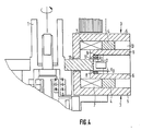
- numeral 1 indicates a main rotary shaft which is rotatably provided with an armature disk 2 thereby forming an integral one unit.
- a pair of bearings elements 3, 3 are disposed on opposite sides in the axial direction of the armature disk 2 putting the disk 2 therebetween.
- Each of the bearing elements 3, 3 comprises a pair of pole pieces 5, 6 mounted on two pole faces of a permanent magnet 4.
- Each of the pole pieces 5, 6 has a part extending in parallel with the armature disk 2 and a top end part further extending from the mentioned part to a position adjacent the armature disk.
- a control coil 7 is disposed between the mentioned pair of pole pieces 5, 6 at a position nearer to front end side than the permanent magnet 4.
- a sensor coil 8 is disposed at a position further nearer to front end side than the mentioned control coil 7. The sensor coil 8 is wound in the same direction as the mentioned control coil 7.
- first and second gaps 11, 12 are respectively formed on the tip end sides of the pole pieces 5, 6, and a leakage magnetic path 13 is formed on the base end sides of the pole pieces 5, 6, of which equivalent circuit is shown in Figure 2.
- reference EO indicates magnetomotive force of the permanent magnet 4
- RO indicates internal magnetic resistance thereof
- RL indicates magnetic resistance for leakage flux
- R1 indicates magnetic resistance for the first gap 11
- R2 indicates magnetic resistance for the second gap 12.
- unbalance spring constant as a result of displacement of the armature disk 2 is in proportion to the following expression: 1/[1 + RO/(1 + RO/R1)(R1 + R2)]
- the magnetic resistance of magnetic path of the control coil 7 can be optimized by enlarging the gap between pole faces N and S of the permanent magnet 4, increasing the internal magnetic resistance RO (for instance, by forming the pole pieces 5, 6 of some soft magnetic substance) and forming leakage path of the permanent magnet 4.
- Control characteristics with control current can be improved by disposing the control coil 7 on the side nearer to front end than the permanent magnet 4. As a result of this, not only unbalance spring constant due to displacement of the armature disk can be reduced, but also the entire construction can be simplified.
- FIG 3 is a schematic diagram showing the principle of displacement detection by a displacement detecting sensor.
- the displacement detecting sensor comprises the sensor coil 8 and the armature disk 2 (magnetic substance), and a high frequency current (about 50 KHz) is applied to the coil 8.
- a high frequency current about 50 KHz
- inductance of the coil 8 varies in such a manner that amplitude of the high frequency applied to the coil 8 is modulated.
- modulated amount is detected by a detector as displacement.
- a detector circuit is formed into a bridge comprising two impedances Z0, Z0 and two sensor coils L1, L2 so that displacement signal is outputted by detection circuit, after differentially detecting modulated amount.
Landscapes
- Engineering & Computer Science (AREA)
- General Engineering & Computer Science (AREA)
- Mechanical Engineering (AREA)
- Physics & Mathematics (AREA)
- Electromagnetism (AREA)
- Magnetic Bearings And Hydrostatic Bearings (AREA)
Applications Claiming Priority (2)
| Application Number | Priority Date | Filing Date | Title |
|---|---|---|---|
| JP63254621A JP2961117B2 (ja) | 1988-10-07 | 1988-10-07 | 磁気軸受装置 |
| JP254621/88 | 1988-10-07 |
Publications (3)
| Publication Number | Publication Date |
|---|---|
| EP0362881A2 true EP0362881A2 (de) | 1990-04-11 |
| EP0362881A3 EP0362881A3 (en) | 1990-07-04 |
| EP0362881B1 EP0362881B1 (de) | 1994-01-19 |
Family
ID=17267576
Family Applications (1)
| Application Number | Title | Priority Date | Filing Date |
|---|---|---|---|
| EP89118607A Expired - Lifetime EP0362881B1 (de) | 1988-10-07 | 1989-10-06 | Magnetische Lager-Vorrichtung |
Country Status (5)
| Country | Link |
|---|---|
| US (1) | US5073737A (de) |
| EP (1) | EP0362881B1 (de) |
| JP (1) | JP2961117B2 (de) |
| KR (1) | KR0153451B1 (de) |
| DE (1) | DE68912490T2 (de) |
Cited By (3)
| Publication number | Priority date | Publication date | Assignee | Title |
|---|---|---|---|---|
| US5406157A (en) * | 1992-08-22 | 1995-04-11 | The Glacier Metal Company Limited | Electromagnetic bearing arrangement |
| FR2720457A1 (fr) * | 1994-05-30 | 1995-12-01 | Samsung Electro Mech | Palier magnétique de butée. |
| US6008558A (en) * | 1998-09-17 | 1999-12-28 | Sundstrand Corporation | L-shaped magnetic thrust bearing |
Families Citing this family (3)
| Publication number | Priority date | Publication date | Assignee | Title |
|---|---|---|---|---|
| US5660397A (en) * | 1994-09-23 | 1997-08-26 | Holtkamp; William H. | Devices employing a liquid-free medium |
| DE19823630C2 (de) * | 1998-05-27 | 2003-08-21 | Pmdm Prec Motors Deutsche Mine | Motorlager für schnelldrehende Kleinmotoren |
| EP1679492A1 (de) * | 2005-01-11 | 2006-07-12 | Mecos Traxler AG | Wirbelstromsensor und Magnetlagervorrichtung |
Family Cites Families (9)
| Publication number | Priority date | Publication date | Assignee | Title |
|---|---|---|---|---|
| DE2355104A1 (de) * | 1973-11-03 | 1975-05-15 | Bbc Brown Boveri & Cie | Elektromagnetisches axiallager |
| FR2377549A1 (fr) * | 1977-01-12 | 1978-08-11 | Europ Propulsion | Montage de rotor court de grand diametre |
| US4167296A (en) * | 1977-12-30 | 1979-09-11 | Sperry Rand Corporation | Protective control system for magnetic suspension and magnetically suspended devices |
| JPS5881217A (ja) * | 1981-11-11 | 1983-05-16 | Seiko Instr & Electronics Ltd | 5自由度制御形磁気軸受装置 |
| US4609869A (en) * | 1983-04-13 | 1986-09-02 | Electro Corporation | Magnetic sensor and circuit for detecting the edge of a target as it passes the centerline of the sensor |
| EP0192836A3 (de) * | 1985-03-01 | 1988-07-20 | Maschinenfabrik Rieter Ag | Verwendung einer magnetischen Lageranordnung |
| US4642501A (en) * | 1985-10-15 | 1987-02-10 | Sperry Corporation | Magnetic suspension and pointing system with flux feedback linearization |
| JPH0198708A (ja) * | 1987-10-07 | 1989-04-17 | Ebara Res Co Ltd | ラジアル磁気軸受装置 |
| US4920291A (en) * | 1989-01-19 | 1990-04-24 | Contraves Goerz Corporation | Magnetic thrust bearing with high force modulation capability |
-
1988
- 1988-10-07 JP JP63254621A patent/JP2961117B2/ja not_active Expired - Lifetime
-
1989
- 1989-10-06 EP EP89118607A patent/EP0362881B1/de not_active Expired - Lifetime
- 1989-10-06 DE DE68912490T patent/DE68912490T2/de not_active Expired - Fee Related
- 1989-10-07 KR KR1019890014499A patent/KR0153451B1/ko not_active Expired - Fee Related
-
1990
- 1990-07-27 US US07/560,460 patent/US5073737A/en not_active Expired - Fee Related
Cited By (3)
| Publication number | Priority date | Publication date | Assignee | Title |
|---|---|---|---|---|
| US5406157A (en) * | 1992-08-22 | 1995-04-11 | The Glacier Metal Company Limited | Electromagnetic bearing arrangement |
| FR2720457A1 (fr) * | 1994-05-30 | 1995-12-01 | Samsung Electro Mech | Palier magnétique de butée. |
| US6008558A (en) * | 1998-09-17 | 1999-12-28 | Sundstrand Corporation | L-shaped magnetic thrust bearing |
Also Published As
| Publication number | Publication date |
|---|---|
| KR900006696A (ko) | 1997-05-08 |
| DE68912490T2 (de) | 1994-08-11 |
| DE68912490D1 (de) | 1994-03-03 |
| US5073737A (en) | 1991-12-17 |
| JPH02102919A (ja) | 1990-04-16 |
| JP2961117B2 (ja) | 1999-10-12 |
| KR0153451B1 (ko) | 1998-12-01 |
| EP0362881B1 (de) | 1994-01-19 |
| EP0362881A3 (en) | 1990-07-04 |
Similar Documents
| Publication | Publication Date | Title |
|---|---|---|
| EP0362882A2 (de) | Magnetlager | |
| EP0121007B1 (de) | Ein kombinierter Lagesensor-Stellmagnet | |
| US5844339A (en) | Active magnetic bearing with auto position-detection | |
| US6617722B2 (en) | Magnetic levitation rotating machine | |
| EP1124309A2 (de) | Positionsdetektor des magnetischen Pols eines Rotors | |
| JPH01187424A (ja) | トルクセンサ | |
| EP0457389A1 (de) | Elektromagnetisches Antriebssystem | |
| EP0435232B1 (de) | Verschiebungssensor vom Induktionstyp mit Unempfindlichkeit gegenüber externen magnetischen Feldern | |
| EP1146319B1 (de) | Positionsgeber | |
| EP0362881A2 (de) | Magnetische Lager-Vorrichtung | |
| US7061231B2 (en) | Device for measuring displacement including a displacement sensor with a detection coil and excitation coils | |
| JPH1014192A (ja) | モータ | |
| US3155437A (en) | Electromagnetic bearing | |
| US5962940A (en) | High specific load capacity radial magnetic bearing actuator | |
| JP2003130605A (ja) | 磁気式変位センサ装置 | |
| JPS6243429B2 (de) | ||
| US7719151B2 (en) | Active magnetic bearing with automatic detection of the position thereof | |
| EP0224377B1 (de) | Geschwindigkeitsmessaufnehmer | |
| JPH02201101A (ja) | 磁気軸受用変位センサ | |
| JPH06147812A (ja) | 回転体の位置検出装置 | |
| JPH0566102A (ja) | 位置検出装置 | |
| JPH10206251A (ja) | トルク検出装置 | |
| JPH04361101A (ja) | 位置検出装置 | |
| JPH0739930B2 (ja) | 回転体の位置検出器 | |
| JPS60210151A (ja) | 磁石回転型電動機 |
Legal Events
| Date | Code | Title | Description |
|---|---|---|---|
| PUAI | Public reference made under article 153(3) epc to a published international application that has entered the european phase |
Free format text: ORIGINAL CODE: 0009012 |
|
| AK | Designated contracting states |
Kind code of ref document: A2 Designated state(s): DE FR GB |
|
| PUAL | Search report despatched |
Free format text: ORIGINAL CODE: 0009013 |
|
| AK | Designated contracting states |
Kind code of ref document: A3 Designated state(s): DE FR GB |
|
| RHK1 | Main classification (correction) |
Ipc: F16C 39/06 |
|
| 17P | Request for examination filed |
Effective date: 19901227 |
|
| 17Q | First examination report despatched |
Effective date: 19920316 |
|
| GRAA | (expected) grant |
Free format text: ORIGINAL CODE: 0009210 |
|
| AK | Designated contracting states |
Kind code of ref document: B1 Designated state(s): DE FR GB |
|
| REF | Corresponds to: |
Ref document number: 68912490 Country of ref document: DE Date of ref document: 19940303 |
|
| ET | Fr: translation filed | ||
| PLBE | No opposition filed within time limit |
Free format text: ORIGINAL CODE: 0009261 |
|
| STAA | Information on the status of an ep patent application or granted ep patent |
Free format text: STATUS: NO OPPOSITION FILED WITHIN TIME LIMIT |
|
| 26N | No opposition filed | ||
| PGFP | Annual fee paid to national office [announced via postgrant information from national office to epo] |
Ref country code: GB Payment date: 19951005 Year of fee payment: 7 |
|
| PGFP | Annual fee paid to national office [announced via postgrant information from national office to epo] |
Ref country code: FR Payment date: 19951018 Year of fee payment: 7 |
|
| PGFP | Annual fee paid to national office [announced via postgrant information from national office to epo] |
Ref country code: DE Payment date: 19951221 Year of fee payment: 7 |
|
| PG25 | Lapsed in a contracting state [announced via postgrant information from national office to epo] |
Ref country code: GB Effective date: 19961006 |
|
| GBPC | Gb: european patent ceased through non-payment of renewal fee |
Effective date: 19961006 |
|
| PG25 | Lapsed in a contracting state [announced via postgrant information from national office to epo] |
Ref country code: FR Effective date: 19970630 |
|
| PG25 | Lapsed in a contracting state [announced via postgrant information from national office to epo] |
Ref country code: DE Effective date: 19970701 |
|
| REG | Reference to a national code |
Ref country code: FR Ref legal event code: ST |