EP0363943B1 - Procédé pour la production des données de demi-teintes - Google Patents
Procédé pour la production des données de demi-teintes Download PDFInfo
- Publication number
- EP0363943B1 EP0363943B1 EP89118918A EP89118918A EP0363943B1 EP 0363943 B1 EP0363943 B1 EP 0363943B1 EP 89118918 A EP89118918 A EP 89118918A EP 89118918 A EP89118918 A EP 89118918A EP 0363943 B1 EP0363943 B1 EP 0363943B1
- Authority
- EP
- European Patent Office
- Prior art keywords
- halftone
- elements
- dither matrix
- subsections
- filling
- Prior art date
- Legal status (The legal status is an assumption and is not a legal conclusion. Google has not performed a legal analysis and makes no representation as to the accuracy of the status listed.)
- Expired - Lifetime
Links
- 238000000034 method Methods 0.000 title claims description 29
- 239000011159 matrix material Substances 0.000 claims description 32
- 238000007648 laser printing Methods 0.000 claims description 2
- 230000001186 cumulative effect Effects 0.000 claims 1
- 230000000737 periodic effect Effects 0.000 description 20
- 239000011295 pitch Substances 0.000 description 19
- 230000003287 optical effect Effects 0.000 description 7
- 230000008569 process Effects 0.000 description 7
- 238000007639 printing Methods 0.000 description 5
- 239000003086 colorant Substances 0.000 description 4
- 230000008859 change Effects 0.000 description 3
- 238000010586 diagram Methods 0.000 description 3
- 238000006243 chemical reaction Methods 0.000 description 2
- 238000012937 correction Methods 0.000 description 2
- 239000000463 material Substances 0.000 description 2
- 230000007246 mechanism Effects 0.000 description 2
- 238000012986 modification Methods 0.000 description 2
- 230000004048 modification Effects 0.000 description 2
- 238000012545 processing Methods 0.000 description 2
- 229920000535 Tan II Polymers 0.000 description 1
- 230000006978 adaptation Effects 0.000 description 1
- 238000003491 array Methods 0.000 description 1
- 230000015572 biosynthetic process Effects 0.000 description 1
- 238000004891 communication Methods 0.000 description 1
- 230000008878 coupling Effects 0.000 description 1
- 238000010168 coupling process Methods 0.000 description 1
- 238000005859 coupling reaction Methods 0.000 description 1
- 238000005286 illumination Methods 0.000 description 1
- 238000003384 imaging method Methods 0.000 description 1
- 238000004519 manufacturing process Methods 0.000 description 1
- 238000010422 painting Methods 0.000 description 1
- 230000002093 peripheral effect Effects 0.000 description 1
- 230000003252 repetitive effect Effects 0.000 description 1
- 238000012216 screening Methods 0.000 description 1
- 238000000926 separation method Methods 0.000 description 1
- 230000007704 transition Effects 0.000 description 1
- 230000002087 whitening effect Effects 0.000 description 1
Images




Classifications
-
- H—ELECTRICITY
- H04—ELECTRIC COMMUNICATION TECHNIQUE
- H04N—PICTORIAL COMMUNICATION, e.g. TELEVISION
- H04N1/00—Scanning, transmission or reproduction of documents or the like, e.g. facsimile transmission; Details thereof
- H04N1/46—Colour picture communication systems
- H04N1/52—Circuits or arrangements for halftone screening
Definitions
- This invention relates to a method for forming halftone data for flat bed type color scanners or the like, and more particularly to a method for forming halftone data including scanning of an original comprising color images of a continuous tone to obtain image signals, and using the image signals to fill the elements of a square dither matrix subdivided into four square subsections in order to form multicolor half tone gradation images formed by square dots comprising a matrix array of pixels which are reproducible by laser printing, and wherein each pixel corresponds to an element of the dither matrix.
- the method according to the invention takes into consideration the difference in halftone screen percentage of respective dots in order to avoid a tone jump when image signals are obtained by scanning an original comprising color images in continuous tone, and are superimposed with halftone screen signals which are electrically generated so as to form four-color separated halftone gradation images in C (cyan), M (magenta), Y (yellow) and K (black).
- Such an image scanning/reading/recording system comprises basically an input section, a controller and an output section. More particularly, the system includes an input section where image signals are picked up by the illumination, color separation and photometric systems to convert image information photoelectrically, and the controller which processes the information in arithmetic operation such as gradation correction, color correction, contour emphasis, conversion from R (red), G (green), B (blue) ⁇ C,M,Y, K and the like depending on the plate-making conditions.
- the processed image information is converted into optical signals such as laser beams by the output section to be printed in the form of images on a recording medium comprising a photosensitive material.
- the medium is developed by a predetermined developing device and used for printing and so on as the original film plates.
- the original to be printed is a photograph or a painting of continuous lone images
- the original should be divided into dots to express the density of images.
- the continuous tone images are therefore transformed into halftone gradation images which are a group of dots in the sizes which are different depending on the density thereof.
- As a method for forming such dots there has been proposed a method which irradiates optical signals depending on the continuous tone images on a recording medium via a contact screen placed on a film.
- the contact screen comprises arrays of dots with blurred circumferences.
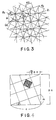
- the reference numeral 100 denotes a basic periodic section of the halftone screen which is electrically formed.
- the halftone screen formed by repetition of the same pattern, and the minimum unit thereof is the basic periodic section 100.
- the basic periodic section 100 comprises eight scanning lines S 1 through S 8 arranged in parallel to each other in the direction of Y axis.
- the scanning lines S 1 through S 8 form respectively parts of the basic periodic 100 with unique voltage signals which change along the recording direction X.
- the respective voltages of the scanning lines S 1 , S 2 , S 4 and S 5 are set at a high level when they are passing through a point A through a point D in a dot section 101 while the voltage of the scanning line S 3 is set at a low level when it passes through the point E.
- the voltages of the respective scanning lines S 1 through S 5 are set to gradually decrease from the points A through D toward the point E.
- the voltage signals at the scanning lines S 1 through S 8 may be formed into the halftone screen signals by, for example, superposing plural alternating voltage signals of a triangle shape of different periods and gradually shifting their phases for each scanning line.
- the halftone screens are formed respectively in the form rotated from the recording direction X at a predetermined angle ⁇ in order to prevent generation of Moiré patterns at the time of superposing.
- a basic periodic section 100 which is formed as above is generated periodically at a frequency sufficient to cover the scanning area of the original to form the halftone screen.
- the halftone screen signals forming such a halftone screen are superposed with the image signals which are optically read from the original at the input section of the image scanning/ reading/recording system in order to form the halftone gradation images on the original film plate.
- Document DE-A-2934436 teaches a method for halftone screening by using a predetermined dot mapping program called up from a memory in accordance with the measured grey scale value of an image dot in order to enhance the printing quality.
- a halftone plate of an area modulation type for color printing is characterized by the number of screen lines (e.g. the number of lines/inch: LPI), the screen angle (m/n) and the dot patterns.
- the screen angle is a rational number defined by m/n of FIG. 1, and is required for each of four colors of the four colors of C,M,Y and K.
- the screen angle and the dot patterns are formed with the method disclosed in Japanese Patent Publication No.49361/1977 mentioned above.
- An arbitrary number of the screen lines may easily be obtained in the drum type color scanners simply by changing the imaging magnification with optical zooming. but in the flat bed (plane) type color scanners, the optical zooming is quite difficult.
- This invention was contrived to eliminate such conventional problems and aims to provide a halftone data forming method for flat bed type color scanners which can change the number of screen lines arbitrarily without changing the scanning pitch or the size of the light spot and which can prevent generation of the tone jumps.
- the above object is solved by a method as initially specified characterised in that the filling of the elements of the dither matrix with increasing image signal levels is carried out such that at first the filling of two of said subsections being positioned on a diagonal of the dither matrix is completed before the filling of the remaining subsections starts, the filling of each subsection is carried out such that each added element is adjacent to already present elements in order to form contiguous areas, the filling of the first two subsections is completed such that the elements being positioned each one on one of the corners of each one of two parallel diagonals of said two subsections are filled as the latest, and the filling of the elements on the corners of the remaining diagonals is completed before all the elements in the corners on said parallel diagonals are filled, and before a number of elements corresponding to 2% or more of the number of elements of the whole dither matrix remains still to be filled in the said subsections.
- this invention when separated halftone gradation images of C,M,Y and K are being formed, a light spot of predetermined size is exposed to light and scanned while the number of pitches is being restricted in order to obtain an arbitrary number of the screen lines. Since the number of the screen lines is defined with the number of pitches, this invention method may easily be applied to color scanners of the flat bed type with conventional screen angles and dot patterns.
- halftone screen signals or data of a dither matrix are re-arranged in order to prevent tone jumps when the images are outputted.
- angles of the four plates of C,M,Y and K are selected to be 0° , 15° , 45° and 75° , and the Y-plate is allotted at the angle 0° , and the other three plates of C,M and K are allotted at the remaining three angles respectively. It is known empirically that the Moiré pattern by the Y-plate is not visually recognizable, and therefore the Moiré pattern caused by the remaining plates of C,M and K, should be dealt with.
- the Moiré patterns with short period are permissible as fine Moiré patterns, they would appear as conspicuous patterns with a higher period. It is therefore desirable that the angle ⁇ formed between the screens should be within ⁇ 15° from 45° or in the scope ranging from 30° to 60° .
- m , n and a are integers, and the numerical values are given in a manner to satisfy the following formula or the conditions to dissolve a single Moiré pattern disclosed in Japanese Patent Laid-open (kokai) No. 188564/1987 wherein ⁇ is an integer.
- a m 2 + n 2 n ⁇ ⁇
- the primary Moiré pattern produced by the two plates of 45° ⁇ (30° ⁇ ⁇ ) (provided, however, the angles 15° and 75° are nominal angles) takes place precisely at 45° .
- the sufficient condition to prevent occurrence of the secondary Moiré pattern is the condition to the period of the primary Moiré pattern agree with the dot interval of the third plate of 45° .
- the line interval d 15 at 15° becomes as expressed in equation (12) below.
- d 15 p ⁇ a 0 m 0 2 +n 0 2
- the line interval d 45 at 45° is expressed as below.
- d 45 p ⁇ a 1 / 2
- the real angle ⁇ 15 for 15° is expressed as below.
- ⁇ 15 tan -1 (m 0 /n 0 )
- the real angle ⁇ 75 at 75° is expressed as below.
- ⁇ 75 tan -1 (n 0 /m 0 ) If the primary Moiré pattern is formed with patterns of 15° and 75° in the direction of 45°, the following relations (16) and (17) are obtained.
- Those marked with asterisk " ⁇ " represents Moiré patterns with relatively longer periods while the rest represent the conditions where no Moiré pattern is formed. Even with the conditions marked with " ⁇ " , they would not present a significant problem in practice as their period is long.
- the number of screen lines of 150 and 120 lines can be obtained by using 12.5 ⁇ m as the scanning pitch or 10/9 times of 11.25 ⁇ m.
- the Table 2 shows the results of combination of the screen lines obtained by the scanning pitches 11.25 ⁇ m and 12.5 ⁇ m.
- the coarse screen line numbers 65 and 85 use the pitch of 11.25 ⁇ m which is twice as much as 11.25 ⁇ m. If the scanning pitch P is selected to be 2.25 ⁇ m, then arbitrary number of the screen lines may be selected with four colors without Moiré patterns, but the realization of the scanning pitch 2.25 ⁇ m has two problems. One problem lies in the difficulty to focus the light beam (light spot) at 2.25 ⁇ m and the other problem is that the scanning speed becomes too slow with the scanning pitch of 2.25 ⁇ m while the data capacity increases remarkably. Because of the above two reasons, selection of a scanning pitch as small as 2.25 ⁇ m is not suitable.
- FIG.5 shows the structure of a system which reads images with a color scanner or the like, processes them in halftone and records them in images. More particularly, the image signals read by an image input section 100 are digitized by an A/D converter 101, processed for gradation conversion, contour emphasis and so on by a signal processing section 102 and inputted to a dot converting section 103. The image data which are converted into dots by the dot converting section 103 are inputted to a D/A converter 104, converted into analog values and recorded in images by an image output section 105.
- FIG.6 shows the light beam scanning apparatus 30 comprising a laser diode 32 which outputs laser beam L 1 for synchronization under the control of LD driver 31, and a laser diode 34 which outputs laser beam L 2 for recording under the control of an LD driver 33.
- the laser beam L 1 for synchronization which is outputted from the laser diode 32 is directed to a galvanometer mirror 40 via a collimator 36 and a mirror 38.
- the laser beam L 2 for recording which is outputted from the laser diode 34 is directed to the galvanometer mirror 40 at an angle ⁇ in respect of the laser beam L 1 for synchronization via a collimator 42 and the mirror 38.
- the galvanometer mirror 40 deflects the laser beam L 1 for synchronization and the laser beam L 2 for recording through reflection when the mirror is vibrated at a high speed.
- the laser beams L 1 and L 2 which have been reflected and deflected by the galvanometer mirror 40 are directed respectively to a synchronization signal generator 50 and an image recording section 52 via a scanning lens 48 comprising an f ⁇ lens.
- the synchronizing laser beam L 1 enters the scanning lens 48 at an incident angle of ⁇ in respect of the optical axis and directed to the synchronizing signal generator 50 via the peripheral side of the scanning lens 48.
- the recording laser beam L 2 enters the scanning lens 48 within the plane including the optical axis and directed to the image recording section 52 via the center of the scanning lens 48.
- the synchronizing signal generator 50 includes grids 56 which are formed with a large number of slits 54 at uniform intervals in the scanning direction of the synchronizing laser beams L 1 , and the synchronizing laser beams L 1 is directed into the grids 56 via a mirror 58.
- a light condensing rod 57 is provided on the back surface of the grids 56, and the synchronizing laser beam L 1 is directed to photodetectors 60a and 60b on both sides of the rod via the light condensing rod 57 and converted into electric signals.
- the electric signals from the photodetectors 60a and 60b are multiplied by a PLL (Phase Locked Loop) multiplier 62 and supplied to an output controller 64 as a synchronizing signal.
- the output controller 64 controls the LD driver 33 based on the synchronizing signals and image signals. As shown in Table 2, once the number of screen lines and screen angles are determined, the step proceeds to designing a dot pattern.
- FIG.7 shows a dot pattern ( template or dither matrix ) of 0° with 175 lines.
- dot patterns template data
- the template data are usually stored either in a floppy disc or an ROM of the image output section 105, and at the time point when the number of screen lines and the screen angle are selected, a scanning pitch p is selected from the table and a circuit is set to be controlled with the selected pitch p .
- the data of the template data is read out in an RAM region.
- FIG.9 with the template data 1 and the image signals 2, halftone data 3 are formed.
- the template data 1 which are read out are compared to the image data 2, and when the image data 2 are larger, "1 " is outputted, and when they are smaller, "0 " is outputted.
- the halftone data 3 is obtained with which light is modulated to expose a photosensitive material to obtain a halftone plate.
- the method for forming a halftone screen by the dot converting section 103 is described below.
- FIG.10 shows an example of the halftone screen signals wherein a basic periodic section 10 of a halftone screen comprising 100-halftone data is shown.
- the basic periodic section 10 is defined with the points A through D to be a halftone section 12 at a screen angle ⁇ .
- the basic periodic section 10 including the halftone section 12 may become the minimum unit of the halftone screen only when the screen angle ⁇ holds the relation below with the rational tangent wherein n and m are integers.
- tan ⁇ m n
- n ⁇ L ⁇ ⁇ P
- n ⁇ L denotes a length either in the X direction or the Y direction of the basic periodic section 10 when a side of a square forming the halftone section 12 in either the X direction or the Y direction is denoted as L
- P denotes a width of the halftone block formed with a halftone data
- ⁇ denotes the number of the halftone data forming the basic periodic section 10 in either the X direction or the Y direction .
- the similar relation can also be obtained in respect of the direction X.
- the distance l in the above case can be expressed as below.
- l L ⁇ cos 2 ⁇ ⁇ tan ⁇ From the formulas (23), (24) and (25), the relation below holds.
- the basic periodic section 10 can be structured by repeating generating the halftone data between the points A and B in the direction Y.
- the basic periodic section 10 can be expressed with the halftone in an amount of ⁇ / ⁇ determinable by the formula (5).
- the basic periodic section 10 can be expressed with twenty halftone data a 0 through a 19 of which amount is one fifth of the data.
- FIG.11 shows an embodiment of a circuit which is used to generate the halftone gradation image signals.
- the circuit comprises two counters 14 and 16, an address converter 18, a halftone data (dither matrix data) memory 20, a line memory 22 and a binary signal generator 24. Out of preset plural halftone original data 26 selected desirable ones depending on the level of the halftone resolution and the screen angle ⁇ to be transferred and stored in the halftone data memory 20.
- the counter 14 counts the clock signal ⁇ x in the main scanning direction of the continuous tone images and supplies them as an address signal X to the address converter 18.
- the counter 16 counts the clock signal ⁇ Y in the auxiliary scanning direction of the continuous tone images and supplies them to the address converter 18 as an address signal Y.
- the address converter 18 converts the address signals (X, Y) of the halftone data at the basic periodic section 10 into the address signals (x, y) of the halftone data a 0 through a 19 stored in the halftone data memory 20 and is structured as shown in FIG.12. More specifically, the address converter 18 includes a remainder calculating section 183 to which the address signal X is supplied via an adder 182 and a remainder calculating section 184 to which address signal Y is supplied.
- the adder 182 is supplied with an adding signal F(Y) selected by the address signal Y from an off-set table 181.
- the off-set table 181 comprises plural data which are determinable by combination of the screen angle ⁇ and the halftone resolution level similarly in the case of the halftone original data 26.
- the remainder calculating section 183 calculates the address signal x based on the equation below.
- x MOD( X + F(Y), N x ) wherein N x denotes the number of the halftone data in the direction X
- the remainder calculating section 184 calculates the address signal y based on the formula below.
- y MOD(Y,N y ) wherein N y denotes the number of the halftone data in the direction of Y.
- the line memory 22 is supplied with the continuous tone image signals and the clock signal ⁇ x in the main scanning direction, and the outputs from the line memory 22 and the halftone data memory 20 are supplied respectively to the binary signal generator 24.
- the binary signal generator 24 compares the halftone data with the image signals and outputs the results of comparison as the halftone gradation image signals.
- a method to convert the continuous tone image signals into the halftone gradation image signals by using the basic periodic section 10 shown in FIG.10 is described below.
- Halftone data of various levels of the screen angle ⁇ and the halftone resolution are stored in the halftone original data 26. Out of these data, the halftone data a 0 through a 19 are selected and loaded at the address (x, y) in the halftone data memory 20.
- the address (x, y) is set within the range (0, 0) through (9, 1). Therefore, when an address signal (X, Y) from the counters 14 and 16 based on the clock signals ⁇ x and ⁇ y are inputted to the address converter 18.
- the address converter 18 converts the address signals (X, Y) into the address signals (x, y) of the halftone data a 0 through a 19 . In other words.
- the address signal F(Y) becomes "4" based on the relation shown in FIG.13, and therefore (x,y) become (4,0) from the relation held in the formulas (27) and (28). Accordingly, the address converter 18 selects the halftone data a 4 out of the halftone data a 0 through a 19 stored in the halftone data memory 20, and supplies the data to the binary signal generator 24. Similarly, all of the halftone data a 0 through a 19 which form the basic periodic section 10 are sequentially supplied to the binary signal generator 24.
- the binary signal generator 24 is supplied with the continuous tone image signal based on the clock signal ⁇ x from the line memory 22 in addition to the halftone data a 0 through a 19 .
- the binary signal generator 24 compares the halftone data a 0 through a 19 with the continuous tone image signals, and outputs the result of the comparison in the form of the halftone gradation image signals or ON/OFF signals.
- the halftone signals are converted into optical signals such as laser beams and irradiated on a film by a device shown in FIG.6 to become the halftone gradation images.
- a tone jump tends to occur usually at near 50% in a square dot. This is attributable to the fact that the scanning beam has an extensive width, and therefore the tone jump tends to occur at a level from which blackened portions start to be coupled between adjacent dots.
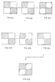
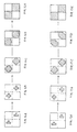
- a dither matrix is used as FIG.8 the ratio of the blackened portion increases in the process FIGs.14A ⁇ 14B ⁇ 14C or FIGs.16A ⁇ 16B ⁇ 16C ⁇ 16D ⁇ 16E.
- the dither matrix is formed as shown in FIG.19 with difference in dot percentage between the first and the second contacts by first connecting one contact and then the other contact as shown in FIG.15B to form a square pattern as shown in FIG.15C.
- the required difference in dot percentage is about 2% or more.
- the dot shapes at various levels of the halftone data will become as shown in FIGs.17A through 17E when the dither matrix is used.
- the tone jump tends to occur at the level where the blackening starts in the main scanning direction. This is because due to the extensive width of the scanning beam, the dot area does not increase smoothly.
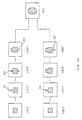
- the tone jump were likely to occur in the process of (A1) ⁇ (A2) or (A2) ⁇ (A3) in FIG.20.
- P1 through P5 in FIG.20 show respectively the minimum unit of dot structure.
- FIG.21 shows the dither matrix wherein the difference in dot ratio between the dots where the blackening starts in the main scanning direction or between dots where the whitening ends is 2% or higher to prevent the tone jumps.
- the tone jumps tended to occur at the transitions from (B1) ⁇ (B2) and (B3) ⁇ (B4) in FIG.20, but as the levels of (B1) ⁇ (B2) and (B3) ⁇ (B4) were separated to a certain extent, the number of the tone jumps was less than the dither matrix in FIG.8 as the whole halftone gradation.
- the whitened portion the similar fact applied only if the relation of negative vs. positive is reversed.
- the halftone data assumes the forms as shown in FIG.18A through FIG.18E at various levels of the halftone data when the dither matrix of FIG.21 was used.
- the letter (A) represents the level where the blackened pixels exist in the number of 1 to 4, (B) in the number of 1 to 5, (C) in the number of 1 to 13, (D) in the number of 1 to 19, and (E) in the number of 1 to 25.
- this invention method for forming halftone data can provide a desirable number of screen lines by exposing and scanning a predetermined size of a light spot at a predetermined pitch and by controlling the number of pitches when a multi-colored separated halftone gradation images are formed by combining all of C,M,Y and K or any two or more colors thereof, and prevent occurrence of the tone jumps by re-arranging the dither matrix or screen signals thereof.
Landscapes
- Engineering & Computer Science (AREA)
- Multimedia (AREA)
- Signal Processing (AREA)
- Facsimile Image Signal Circuits (AREA)
- Image Processing (AREA)
- Color Image Communication Systems (AREA)
Claims (3)
- Procédé de formation de données de demi-teintes incluant le balayage d'un original comprenant des images couleurs d'une teinte continue afin d'obtenir des signaux d'image et l'utilisation des signaux d'image pour remplir les éléments d'une matrice de tremblement carrée subdivisée en quatre sous-sections carrées afin de former des images de gradation de demi-teintes multicouleurs formées par des points carrés comprenant un réseau matriciel de pixels qui sont reproductibles au moyen d'une impression laser, et dans lequel chaque pixel correspond à un élément de la matrice de tremblement,
caractérisé en ce que :
le remplissage des éléments de la matrice de tremblement avec des niveaux de signal d'image croissants est mis en oeuvre de telle sorte que :a) tout d'abord le remplissage de deux desdites sous-sections qui sont positionnées sur une diagonale de la matrice de tremblement soit terminé avant que le remplissage des sous-sections restantes ne démarre ;b) le remplissage de chaque sous-section soit mis en oeuvre de telle sorte que chaque élément ajouté soit adjacent à des éléments déjà présents afin de former des zones contiguës ;c) le remplissage des deux premières sous-sections soit terminé de telle sorte que les éléments qui sont positionnés chacun sur l'un des angles de chacune de deux diagonales parallèles desdites deux sous-sections soient remplis en dernier ; etd) le remplissage des éléments sur les angles des diagonales restantes soit terminé avant que tous les éléments au niveau des angles sur lesdites diagonales parallèles soient remplis ; ete) avant qu'un certain nombre d'éléments correspondant à 2 % ou plus du nombre d'éléments de la matrice de tremblement totale restent encore à remplir dans lesdites sous-sections. - Procédé selon la revendication 1, caractérisé en ce que :
les matrices de tremblement des images couleurs sont tournées les unes par rapport aux autres afin d'éviter des motifs de moirage. - Procédé selon la revendication 2, caractérisé en ce que :
lesdites matrices de tremblement tournées sont obtenues par le fait qu'un bloc de base d'éléments de la matrice de tremblement est agencé de manière répétée dans la nouvelle matrice dans laquelle les éléments dans les blocs répétés sont décalés cycliquement par rapport à l'agencement dans la matrice de tremblement non tournée au moyen d'une valeur de décalage cumulative qui est déterminée au moyen d'une résolution de demi-teintes et de l'angle de rotation.
Applications Claiming Priority (2)
| Application Number | Priority Date | Filing Date | Title |
|---|---|---|---|
| JP258229/88 | 1988-10-13 | ||
| JP63258229A JP2578947B2 (ja) | 1988-10-13 | 1988-10-13 | 網点データ作成方法 |
Publications (3)
| Publication Number | Publication Date |
|---|---|
| EP0363943A2 EP0363943A2 (fr) | 1990-04-18 |
| EP0363943A3 EP0363943A3 (fr) | 1990-10-17 |
| EP0363943B1 true EP0363943B1 (fr) | 1997-01-02 |
Family
ID=17317312
Family Applications (1)
| Application Number | Title | Priority Date | Filing Date |
|---|---|---|---|
| EP89118918A Expired - Lifetime EP0363943B1 (fr) | 1988-10-13 | 1989-10-11 | Procédé pour la production des données de demi-teintes |
Country Status (4)
| Country | Link |
|---|---|
| US (1) | US5019896A (fr) |
| EP (1) | EP0363943B1 (fr) |
| JP (1) | JP2578947B2 (fr) |
| DE (1) | DE68927606T2 (fr) |
Families Citing this family (14)
| Publication number | Priority date | Publication date | Assignee | Title |
|---|---|---|---|---|
| US5172248A (en) * | 1988-05-18 | 1992-12-15 | Fuji Photo Film Co., Ltd. | Method for forming halftone screen and apparatus therefor |
| JP2618107B2 (ja) * | 1991-03-12 | 1997-06-11 | 三田工業株式会社 | マトリクスアドレス生成装置およびそのアドレス生成装置を含む多値化階調処理装置 |
| JPH077624A (ja) * | 1991-09-09 | 1995-01-10 | Mitsubishi Paper Mills Ltd | 網点画像記録方法 |
| JP2772504B2 (ja) * | 1993-03-26 | 1998-07-02 | 大日本スクリーン製造株式会社 | 網角度が変更可能な網目版画像生成装置 |
| JP3241157B2 (ja) * | 1993-04-19 | 2001-12-25 | 富士写真フイルム株式会社 | 網点画像データ補正方法および補正機能を有する画像処理装置 |
| JP3305495B2 (ja) * | 1994-04-28 | 2002-07-22 | キヤノン株式会社 | 画像処理装置および画像処理方法 |
| JPH09130605A (ja) * | 1995-10-31 | 1997-05-16 | Fuji Photo Film Co Ltd | 網点画像出力方法およびその装置 |
| US6208430B1 (en) * | 1998-01-07 | 2001-03-27 | Xerox Corporation | Increased functionality for Holladay halftoning |
| US7187469B2 (en) | 1998-11-09 | 2007-03-06 | Silverbrook Research Pty Ltd | Pagewidth inkjet printer with high data rate printer architecture |
| US7372598B2 (en) | 1998-11-09 | 2008-05-13 | Silverbrook Research Pty Ltd | Pagewidth inkjet printer with foldable input tray for interface protection |
| AUPP702498A0 (en) | 1998-11-09 | 1998-12-03 | Silverbrook Research Pty Ltd | Image creation method and apparatus (ART77) |
| JP2001169110A (ja) * | 1999-12-10 | 2001-06-22 | Fuji Photo Film Co Ltd | 画像変換装置および画像変換プログラム記憶媒体 |
| US7511857B2 (en) * | 2004-01-26 | 2009-03-31 | Hewlett-Packard Development Company, L.P. | Halftoning method and system |
| JP4756597B2 (ja) * | 2005-11-09 | 2011-08-24 | 株式会社リコー | 画像形成装置および方法 |
Family Cites Families (15)
| Publication number | Priority date | Publication date | Assignee | Title |
|---|---|---|---|---|
| DE2262824C3 (de) * | 1972-12-22 | 1975-07-10 | Dr.-Ing. Rudolf Hell Gmbh, 2300 Kiel | Verfahren zur gerasterten Reproduktion farbiger Halbtonbilder im Ein- oder Mehrfarbendruck |
| DE2852315A1 (de) * | 1978-12-04 | 1980-06-26 | Mohn Gmbh Reinhard | Verfahren zur herstellung von rasterauszuegen |
| DE2934436C2 (de) * | 1979-08-25 | 1986-01-30 | Bosse, Rolf, Dr.-Ing., 8011 Neukeferloh | Verfahren zur Aufzeichnung gerasterter Bilder |
| JPS5978353A (ja) * | 1982-10-28 | 1984-05-07 | Dainippon Screen Mfg Co Ltd | 網目版画像記録装置における網点形成方法 |
| US4547814A (en) * | 1982-12-06 | 1985-10-15 | Dainippon Screen Seizo Kabushiki Kaisha | Method of recording a halftone picture electronically |
| JPH0691604B2 (ja) * | 1983-09-02 | 1994-11-14 | 株式会社リコー | 階調情報変倍処理方法 |
| US4719506A (en) * | 1983-09-30 | 1988-01-12 | Buren Keith E Van | Method for predictably determining halftone dot sizes when altering color in a color separation process prior to scanning |
| DE3376766D1 (en) * | 1983-12-29 | 1988-06-30 | Agfa Gevaert Nv | Photographic method for the production of documents |
| JPS61203785A (ja) * | 1985-03-07 | 1986-09-09 | Dainippon Screen Mfg Co Ltd | 2値画像デ−タの平滑化処理方法及びその装置 |
| JPS61225973A (ja) * | 1985-03-30 | 1986-10-07 | Konishiroku Photo Ind Co Ltd | 多色像形成装置 |
| JPH0683374B2 (ja) * | 1986-02-14 | 1994-10-19 | 富士写真フイルム株式会社 | 網点画像の形成方法 |
| JPS62284580A (ja) * | 1986-06-02 | 1987-12-10 | Fuji Xerox Co Ltd | 網点画像形成方法 |
| JPH0691612B2 (ja) * | 1987-03-11 | 1994-11-14 | 株式会社ヤマトヤ商会 | 画像の階調変換方法 |
| JPS63296563A (ja) * | 1987-05-28 | 1988-12-02 | Matsushita Electric Ind Co Ltd | 画信号処理装置 |
| JPS6444681A (en) * | 1987-08-12 | 1989-02-17 | Fuji Photo Film Co Ltd | Dot screen forming method |
-
1988
- 1988-10-13 JP JP63258229A patent/JP2578947B2/ja not_active Expired - Lifetime
-
1989
- 1989-10-11 EP EP89118918A patent/EP0363943B1/fr not_active Expired - Lifetime
- 1989-10-11 DE DE68927606T patent/DE68927606T2/de not_active Expired - Lifetime
- 1989-10-12 US US07/420,414 patent/US5019896A/en not_active Expired - Lifetime
Non-Patent Citations (1)
| Title |
|---|
| J.C.Stoffel and J.F.Moreland, "A Survey of Electronics for Pictorial Image Production", IEEE Transactions on Communications, Vol. COM-29, No.12, December 1981, pages 1904 to 1907 * |
Also Published As
| Publication number | Publication date |
|---|---|
| JP2578947B2 (ja) | 1997-02-05 |
| US5019896A (en) | 1991-05-28 |
| DE68927606T2 (de) | 1997-04-24 |
| JPH02105678A (ja) | 1990-04-18 |
| EP0363943A3 (fr) | 1990-10-17 |
| DE68927606D1 (de) | 1997-02-13 |
| EP0363943A2 (fr) | 1990-04-18 |
Similar Documents
| Publication | Publication Date | Title |
|---|---|---|
| US4903123A (en) | Image processing apparatus using inclined line screens to reduce Moire | |
| EP0363943B1 (fr) | Procédé pour la production des données de demi-teintes | |
| EP0204094B2 (fr) | Procédé d'impression du type d'enregistrement par balayage et appareil pour le mettre en oeuvre | |
| US4149183A (en) | Electronic halftone generator | |
| EP0525520B1 (fr) | Système de tramage et de reproduction en couleurs pour l'impression offset | |
| EP0201674B1 (fr) | Procédé pour reproduire des images numériques à teintes multiples à l'aide d'une imprimante à deux teintes et à dimension de point fixe | |
| US4196451A (en) | Electronic halftone generator | |
| US4987498A (en) | Method of forming halftone screen | |
| EP0213891B1 (fr) | Appareil de traitement d'image | |
| EP0409608B1 (fr) | Méthode pour l'impression offset ou systèmes d'impression similaires | |
| EP0264754A2 (fr) | Procédé d'enregistrement d'images en semi-demi-teintes | |
| JP3429300B2 (ja) | 中間調画像生成に用いるためのスクリーン装置 | |
| US5515456A (en) | Process for providing digital halftone image with random error diffusion, color correction and enlargement | |
| US6081349A (en) | Image processing device, image processing system, and method for generating screens for image processing | |
| JPH0879552A (ja) | カラードキュメント印刷装置及び方法 | |
| EP0493935B1 (fr) | Système électronique numérique d'impression en demi-teintes | |
| US5270835A (en) | Method for forming halftone screen and apparatus therefor | |
| EP0235631B1 (fr) | Procédé pour faire un écran de demi-teintes | |
| EP0342845B1 (fr) | Création d'images en demi-teintes | |
| US5172248A (en) | Method for forming halftone screen and apparatus therefor | |
| EP0342640B1 (fr) | Procédé pour créer une trame de demi-teintes | |
| EP0488324B1 (fr) | Procédé et appareil pour la production d'images à demi-teinte | |
| EP0361538A1 (fr) | Procédé et système pour l'amélioration des bords dans la reproduction d'images numériques à plusieurs niveaux de gris d'une imprimante à points de dimensions fixes | |
| JP2680125B2 (ja) | 網目スクリーン形成方法 | |
| JPH0127627B2 (fr) |
Legal Events
| Date | Code | Title | Description |
|---|---|---|---|
| PUAI | Public reference made under article 153(3) epc to a published international application that has entered the european phase |
Free format text: ORIGINAL CODE: 0009012 |
|
| AK | Designated contracting states |
Kind code of ref document: A2 Designated state(s): DE FR GB |
|
| PUAL | Search report despatched |
Free format text: ORIGINAL CODE: 0009013 |
|
| AK | Designated contracting states |
Kind code of ref document: A3 Designated state(s): DE FR GB |
|
| 17P | Request for examination filed |
Effective date: 19901022 |
|
| 17Q | First examination report despatched |
Effective date: 19921216 |
|
| GRAH | Despatch of communication of intention to grant a patent |
Free format text: ORIGINAL CODE: EPIDOS IGRA |
|
| GRAH | Despatch of communication of intention to grant a patent |
Free format text: ORIGINAL CODE: EPIDOS IGRA |
|
| GRAA | (expected) grant |
Free format text: ORIGINAL CODE: 0009210 |
|
| AK | Designated contracting states |
Kind code of ref document: B1 Designated state(s): DE FR GB |
|
| REF | Corresponds to: |
Ref document number: 68927606 Country of ref document: DE Date of ref document: 19970213 |
|
| ET | Fr: translation filed | ||
| PLBE | No opposition filed within time limit |
Free format text: ORIGINAL CODE: 0009261 |
|
| STAA | Information on the status of an ep patent application or granted ep patent |
Free format text: STATUS: NO OPPOSITION FILED WITHIN TIME LIMIT |
|
| 26N | No opposition filed | ||
| REG | Reference to a national code |
Ref country code: GB Ref legal event code: IF02 |
|
| REG | Reference to a national code |
Ref country code: GB Ref legal event code: 732E |
|
| REG | Reference to a national code |
Ref country code: FR Ref legal event code: TP Ref country code: FR Ref legal event code: CD |
|
| PGFP | Annual fee paid to national office [announced via postgrant information from national office to epo] |
Ref country code: DE Payment date: 20081014 Year of fee payment: 20 |
|
| PGFP | Annual fee paid to national office [announced via postgrant information from national office to epo] |
Ref country code: FR Payment date: 20081014 Year of fee payment: 20 |
|
| PGFP | Annual fee paid to national office [announced via postgrant information from national office to epo] |
Ref country code: GB Payment date: 20081008 Year of fee payment: 20 |
|
| REG | Reference to a national code |
Ref country code: GB Ref legal event code: PE20 Expiry date: 20091010 |
|
| PG25 | Lapsed in a contracting state [announced via postgrant information from national office to epo] |
Ref country code: GB Free format text: LAPSE BECAUSE OF EXPIRATION OF PROTECTION Effective date: 20091010 |