EP0363959A2 - Procédé de régulation de la pression de freinage dans une installation de freinage de véhicule à antiblocage - Google Patents
Procédé de régulation de la pression de freinage dans une installation de freinage de véhicule à antiblocage Download PDFInfo
- Publication number
- EP0363959A2 EP0363959A2 EP89118983A EP89118983A EP0363959A2 EP 0363959 A2 EP0363959 A2 EP 0363959A2 EP 89118983 A EP89118983 A EP 89118983A EP 89118983 A EP89118983 A EP 89118983A EP 0363959 A2 EP0363959 A2 EP 0363959A2
- Authority
- EP
- European Patent Office
- Prior art keywords
- wheel
- speed
- brake
- vehicle
- deceleration
- Prior art date
- Legal status (The legal status is an assumption and is not a legal conclusion. Google has not performed a legal analysis and makes no representation as to the accuracy of the status listed.)
- Granted
Links
Images

Classifications
-
- B—PERFORMING OPERATIONS; TRANSPORTING
- B60—VEHICLES IN GENERAL
- B60T—VEHICLE BRAKE CONTROL SYSTEMS OR PARTS THEREOF; BRAKE CONTROL SYSTEMS OR PARTS THEREOF, IN GENERAL; ARRANGEMENT OF BRAKING ELEMENTS ON VEHICLES IN GENERAL; PORTABLE DEVICES FOR PREVENTING UNWANTED MOVEMENT OF VEHICLES; VEHICLE MODIFICATIONS TO FACILITATE COOLING OF BRAKES
- B60T8/00—Arrangements for adjusting wheel-braking force to meet varying vehicular or ground-surface conditions, e.g. limiting or varying distribution of braking force
- B60T8/32—Arrangements for adjusting wheel-braking force to meet varying vehicular or ground-surface conditions, e.g. limiting or varying distribution of braking force responsive to a speed condition, e.g. acceleration or deceleration
-
- B—PERFORMING OPERATIONS; TRANSPORTING
- B60—VEHICLES IN GENERAL
- B60T—VEHICLE BRAKE CONTROL SYSTEMS OR PARTS THEREOF; BRAKE CONTROL SYSTEMS OR PARTS THEREOF, IN GENERAL; ARRANGEMENT OF BRAKING ELEMENTS ON VEHICLES IN GENERAL; PORTABLE DEVICES FOR PREVENTING UNWANTED MOVEMENT OF VEHICLES; VEHICLE MODIFICATIONS TO FACILITATE COOLING OF BRAKES
- B60T8/00—Arrangements for adjusting wheel-braking force to meet varying vehicular or ground-surface conditions, e.g. limiting or varying distribution of braking force
- B60T8/17—Using electrical or electronic regulation means to control braking
- B60T8/176—Brake regulation specially adapted to prevent excessive wheel slip during vehicle deceleration, e.g. ABS
- B60T8/1764—Regulation during travel on surface with different coefficients of friction, e.g. between left and right sides, mu-split or between front and rear
Definitions
- the invention relates to a method for regulating the brake pressure in an anti-lock vehicle brake system, in which the rotational behavior of a braked wheel is measured and, depending on its slip and / or its deceleration when the brake pressure is exceeded, at least a predetermined threshold value is normally reduced and later increased again.
- the rotation of the individual wheels of the vehicle is constantly monitored and in particular the slippage of the braked wheels and their deceleration are determined in order to determine a tendency of the wheel to lock and to prevent locking.
- the wheel slip or the deceleration indicate a tendency to lock, which is determined by the fact that certain predetermined threshold values with regard to slip and / or deceleration are exceeded, a further increase in the pressure in the brake of the affected wheel is ended or the brake pressure is reduced.
- the wheel speeds of the driven wheels are measured on the motor vehicle, and the wheel acceleration or deceleration is determined for a single wheel by differentiating this speed.
- a so-called vehicle control The speed of rotation of a wheel strongly deviates from the reference speed (so-called negative slip) or the wheel reaches decelerations that are significantly greater than the maximum physically possible vehicle deceleration (i.e. the deceleration that can be achieved with optimal tires and a cheaper road surface with optimal braking), the brake pressure on the wheel in question is reduced (usually by opening a solenoid valve) until the wheel again accelerates above a predetermined threshold value.
- DE-OS 33 45 729 takes into account the fact that under certain conditions, braked wheels can show a turning behavior which indicates a strong deceleration, even though the wheel is still running in a good braking condition. Such rotational delays can occur in particular due to axle vibrations and simulate an unstable running of the wheel and therefore trigger undesired control processes, ie an undesired reduction in the brake pressure.
- the threshold value which is decisive for initiating the control is varied after a first control cycle as a function of the acceleration of acceleration of the controlled wheel.
- the decisive factor for the shortest braking distance that can be achieved during braking with simultaneous steering stability of the vehicle is the coefficient of adhesion ⁇ between the road surface and the tire of the braked wheel.
- the adhesion coefficient is therefore often referred to in the literature as the "braking force coefficient".
- the coefficient of adhesion ⁇ is dependent not only on many parameters, such as in particular the tire construction, the tire tread, the contact force and the tire pressure, but also to a large extent on the road surface (whether dry, wet or icy).
- the wheel on the outside of the curve has a higher speed than the inside of the curve due to the wheelbase, since it has to travel a greater distance per unit of time.
- a wheel on the inside of the curve is relieved, ie the contact force of a wheel on the inside of the curve is significantly less than that of a wheel on the outside of the curve. This reduces the braking force that can be transmitted when braking on the inside wheel.
- the transferable driving force changes when the vehicle is driven on the inside wheel.
- the turning speed of the inside wheel drops to the turning speed corresponding to the turning radius and the vehicle speed when changing the foot from the accelerator to the brake. In other words, there is a strong deceleration of the wheel on the inside of the curve.
- the ABS control system evaluates this as a tendency of this wheel to lock up and pressure reduction signals are thus generated.
- these pressure reduction signals start much too early because the wheel is not yet in a brake slip. Due to the pressure reduction, the wheel on the inside of the curve will continue to rotate at the relatively high rotational speed and will not experience any significant re-acceleration, so that pressure reduction signals relating to this wheel will continue to be generated.
- the pressure increase gradient i.e. the increase in the pressure increase at the brake cylinder as a function of the pressure in the master cylinder
- the pressure increase gradient is switched to a flat value .
- the brake pressure in the brake cylinder increases with a lower gradient than in the normal case, ie without ABS regulation.
- This flattening of the pressure increase gradient in ABS control is carried out in order to prevent the brake pressure from "overshooting" the optimum value and to achieve the closest possible adaptation of the actual brake pressure curve to the ideal brake pressure curve.
- the invention is intended to remedy this. It is based on the task of a method for regulating the brake pressure in an ABS To provide a system that delivers the shortest possible braking distance even when cornering extremely and possibly turning inside wheels.
- the speed of rotation of a wheel (with which the wheel in question on the inside of the curve is meant here) is compared with the speed of rotation of another wheel on the other side of the vehicle.
- This comparison results in additional conditions for the ABS control in addition to the prior art.
- the "one wheel” is any wheel of the vehicle.
- the control algorithm according to the invention provides that, when a wheel exceeds a predetermined threshold value with regard to the deceleration, at least one determined condition, which results from the comparison of the left and right vehicle wheels, the brake pressure is not yet reduced, contrary to the normal case. For this purpose, it is determined whether the speed of rotation of the observed wheel is greater than that of a wheel arranged on the other side of the vehicle.
- the other wheel being compared also rotates with a deceleration that is still below the threshold value (ie does not indicate a tendency to lock), there is still no reduction in the braking pressure on one wheel.
- the method according to the invention therefore takes into account the chronology of the events.
- pressure reduction is only initiated on the braked wheel if at least two conditions are met, namely firstly the rotational deceleration of the wheel concerned must be above the predetermined threshold value and secondly its rotational speed must be smaller by at least a predetermined difference be than that of another wheel arranged on the other side of the vehicle.
- this other wheel is still running in a stable state, ie shows no tendency to lock.
- the additional condition for pressure reduction on one wheel is lifted, ie one wheel (like the other) is ABS-controlled in a conventional manner.
- the invention provides a different algorithm for the ABS control. This variant is described in claim 2. A supplement can be found in claim 3.
- the rotational speeds v1, v2 are plotted from two wheels arranged on opposite sides of the vehicle over a common time ordinate.
- the course of the rotational speeds indicates that the speed v1 is that of the inside wheel.
- a brake light switch signal "BLS” and a signal “MV” indicating an opening of the solenoid valve are plotted in FIGS. 1a, b, c and d.
- the "BLS” signal stands for brake actuation, which of course can also be determined differently than via the brake light. In other words, when the "BLS” signal changes to the state other than 0, the brake is applied.
- the signal “MV” indicates that a solenoid valve on the wheel concerned is opened, that is, a pressure reduction takes place in the course of an ABS control.
- FIGs. 1a and b show the case in which the inside wheel turns over the speed of the outside wheel during cornering, i.e. the rotational speed v1 of the inner wheel significantly exceeds the rotational speed v2 of the outer wheel, as shown.
- Figs. 1a and 1b differ only in that it is assumed in Fig. 1a that the brake is actuated significantly later than in Fig. 1b, i.e. that signal "BLS" starts in Fig. 1b before the time at which the deceleration of the inside wheel (first derivative of the rotational speed v1) reaches the threshold -b signal, while in Fig. 1a the brake is actuated only after this time becomes.
- the control algorithm is independent of the onset of the in both cases Brake light switch signal "BLS".
- the braking pressure on the wheel on the inside of the curve is not yet reduced at the point in time at which the deceleration reaches the threshold value (this point in time is designated in the FIG. "-B signal"), but later, namely at the point in time at which the rotation speed v1 of the inner wheel by a predetermined difference ⁇ v is less than the rotational speed v2 of the outer wheel.
- the speed difference is set to 12 km / h.
- the brake pressure on the inside wheel is reduced, ie the solenoid valve is opened to reduce pressure.
- the signal "MV" It is assumed that the wheel on the outside of the curve does not yet indicate a tendency to lock, that is to say that it has not yet reached the rotational deceleration threshold value. In the figures, the curve V2 is drawn accordingly.
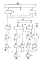
- FIG. 2 shows a block diagram of an exemplary embodiment of a device for carrying out the control algorithm described above. It goes without saying that the regulation can also be carried out with software.
- measurement signals of a wheel speed sensor known per se are converted into speeds v 1 and v 2.
- the speed v1 represents the wheel speed of the inner wheel
- v2 the speed of the outer wheel.
- the speeds determined in this way are fed to the differentiators 4 and 6, which form the wheel accelerations v 1 and v 2.
- the switching signal A2 is formed when the speed v1 is greater than the speed v2.
- a differential speed ⁇ v which corresponds to the maximum possible curve slip, is subtracted from the speed v 1.
- the speed signal A3 obtained in this way is fed together with the speed v2 to a comparator 11 and generates the switching signal C4 there when the speed v2 is greater than A3.
- the wheel slip A 1 is formed from the vehicle reference speed and the wheel speed v 1.
- this slip signal A 1 is compared with a given threshold value ⁇ and then a switching signal C 1 is generated when the threshold value is reached by the slip signal.
- the switching signals C2, A2 and negated C3 are input to an AND gate 13.
- the switching signals C2 and negated C3 are entered and together with the negated brake light switch signal form the switching signal D3.
- the two outputs of these AND stages D2 and D3 form the switching signal E1 via the OR gate 15.
- the OR gate 15 is designed as a memory element, so it has a storing effect.
- the switching signal E1 is reset with a logical "1" from the signals MV or negated C2 or C3.
- the MV signal corresponds to the activation of the solenoid valve.
- the switching signal F 1 is generated when the switching signal D 1 is at a logic "1" level and E 1 is at a logic "0" level.
- the switching signal E1 thus blocks the normal control with a logical “1”, but releases with this "1" another control path via F2, which is provided with the additional condition C4.
- the switching signals D1, E1 and C4 lead in the AND stage 17 to an output signal F2.
- These two signals F1 and F2 form via the OR stage 18, the signal for controlling the solenoid valve on the inside edge of the curve.
Landscapes
- Engineering & Computer Science (AREA)
- Transportation (AREA)
- Mechanical Engineering (AREA)
- Regulating Braking Force (AREA)
Applications Claiming Priority (2)
| Application Number | Priority Date | Filing Date | Title |
|---|---|---|---|
| DE3835095 | 1988-10-14 | ||
| DE3835095A DE3835095A1 (de) | 1988-10-14 | 1988-10-14 | Verfahren zum regeln des bremsdruckes in einer blockiergeschuetzten fahrzeugbremsanlage |
Publications (3)
| Publication Number | Publication Date |
|---|---|
| EP0363959A2 true EP0363959A2 (fr) | 1990-04-18 |
| EP0363959A3 EP0363959A3 (en) | 1990-05-16 |
| EP0363959B1 EP0363959B1 (fr) | 1993-08-04 |
Family
ID=6365162
Family Applications (1)
| Application Number | Title | Priority Date | Filing Date |
|---|---|---|---|
| EP89118983A Expired - Lifetime EP0363959B1 (fr) | 1988-10-14 | 1989-10-12 | Procédé de régulation de la pression de freinage dans une installation de freinage de véhicule à antiblocage |
Country Status (8)
| Country | Link |
|---|---|
| US (1) | US5188432A (fr) |
| EP (1) | EP0363959B1 (fr) |
| JP (1) | JPH03502915A (fr) |
| KR (1) | KR900701580A (fr) |
| BR (1) | BR8907122A (fr) |
| DE (2) | DE3835095A1 (fr) |
| ES (1) | ES2042926T3 (fr) |
| WO (1) | WO1990003904A1 (fr) |
Cited By (3)
| Publication number | Priority date | Publication date | Assignee | Title |
|---|---|---|---|---|
| FR2667558A1 (fr) * | 1990-10-06 | 1992-04-10 | Teves Gmbh Alfred | Agencement de circuit pour systeme de freinage a regulation antiblocage et/ou regulation du glissement de traction. |
| WO1997000799A1 (fr) * | 1995-06-22 | 1997-01-09 | Itt Automotive Europe Gmbh | Procede d'amelioration de la regulation d'un systeme antiblocage |
| WO1998023472A1 (fr) * | 1996-11-26 | 1998-06-04 | Continental Teves Ag & Co. Ohg | Procede et dispositif pour ameliorer le comportement en regulation d'un systeme de freinage antiblocage |
Families Citing this family (8)
| Publication number | Priority date | Publication date | Assignee | Title |
|---|---|---|---|---|
| JP3271778B2 (ja) * | 1991-12-16 | 2002-04-08 | マツダ株式会社 | 車両のスリップ制御装置 |
| JP3723228B2 (ja) * | 1992-02-06 | 2005-12-07 | アイシン精機株式会社 | アンチスキッド制御装置 |
| JPH05213174A (ja) * | 1992-02-06 | 1993-08-24 | Aisin Seiki Co Ltd | アンチスキッド制御装置 |
| JPH07132816A (ja) * | 1993-11-09 | 1995-05-23 | Akebono Brake Ind Co Ltd | アンチロック制御方法 |
| DE10031128B4 (de) * | 2000-06-30 | 2010-07-01 | Robert Bosch Gmbh | Verfahren und Vorrichtung zur Erkennung eines Spurwechsels |
| US20060038443A1 (en) * | 2004-08-20 | 2006-02-23 | Stewart James E | Surface vehicle wheel anti-skid system |
| DE112011105177B4 (de) * | 2011-04-22 | 2022-06-15 | Toyota Jidosha Kabushiki Kaisha | Bremsanlage |
| US10300897B2 (en) * | 2017-05-15 | 2019-05-28 | Goodrich Corporation | Brake load balance and runway centering techniques |
Family Cites Families (12)
| Publication number | Priority date | Publication date | Assignee | Title |
|---|---|---|---|---|
| DE2102131B2 (de) * | 1971-01-18 | 1976-10-28 | Alfred Teves Gmbh, 6000 Frankfurt | Schaltanordnung fuer eine blockiergeschuetzte kraftfahrzeugbremsanlage |
| US3827760A (en) * | 1972-01-17 | 1974-08-06 | Wagner Electric Corp | Wheel slip control system for automotive vehicles and the like |
| IT1071951B (it) * | 1976-12-17 | 1985-04-10 | Fiat Spa | Procedimento e sistema di frenatura per la trasmissione di coppia motrice alla ruota adernete di un asse motore per veicoli a freantura pneumatica ed idraulica tramite rivelazione della velocita' e della accelerazione delle ruote motrici |
| DE2757911A1 (de) * | 1977-12-24 | 1979-06-28 | Bosch Gmbh Robert | Blockierschutz-regeleinrichtung |
| JPS6141657A (ja) * | 1984-07-31 | 1986-02-28 | Nippon Ee B S Kk | アンチスキッド装置用液圧制御装置 |
| JPH0645338B2 (ja) * | 1985-04-09 | 1994-06-15 | 日産自動車株式会社 | アンチスキッド制御装置 |
| US4755945A (en) * | 1986-09-24 | 1988-07-05 | General Motors Corporation | Adaptive mode anti-lock brake controller |
| DE3726998C2 (de) * | 1987-08-13 | 1995-07-06 | Teves Gmbh Alfred | Verfahren und Schaltungsanordnung zur Regelung des Radschlupfes mit einer elektronisch steuerbaren Kraftfahrzeug-Bremsanlage |
| DE3733801A1 (de) * | 1987-09-21 | 1989-03-30 | Wabco Westinghouse Fahrzeug | Antiblockiersystem fuer fahrzeuge |
| JPH01204848A (ja) * | 1988-02-09 | 1989-08-17 | Fuji Heavy Ind Ltd | 自動車のアンチスキッド制御方法 |
| GB2215796A (en) * | 1988-02-09 | 1989-09-27 | Fuji Heavy Ind Ltd | Antilock brake control method for motor vehicles |
| JPH01208258A (ja) * | 1988-02-16 | 1989-08-22 | Fuji Heavy Ind Ltd | 自動車のアンチスキッド制御方法 |
-
1988
- 1988-10-14 DE DE3835095A patent/DE3835095A1/de not_active Ceased
-
1989
- 1989-10-12 US US07/499,254 patent/US5188432A/en not_active Expired - Fee Related
- 1989-10-12 DE DE8989118983T patent/DE58905137D1/de not_active Expired - Fee Related
- 1989-10-12 BR BR898907122A patent/BR8907122A/pt not_active IP Right Cessation
- 1989-10-12 WO PCT/EP1989/001204 patent/WO1990003904A1/fr not_active Ceased
- 1989-10-12 ES ES89118983T patent/ES2042926T3/es not_active Expired - Lifetime
- 1989-10-12 JP JP2500511A patent/JPH03502915A/ja active Pending
- 1989-10-12 EP EP89118983A patent/EP0363959B1/fr not_active Expired - Lifetime
-
1990
- 1990-06-08 KR KR1019900701220A patent/KR900701580A/ko not_active Withdrawn
Cited By (5)
| Publication number | Priority date | Publication date | Assignee | Title |
|---|---|---|---|---|
| FR2667558A1 (fr) * | 1990-10-06 | 1992-04-10 | Teves Gmbh Alfred | Agencement de circuit pour systeme de freinage a regulation antiblocage et/ou regulation du glissement de traction. |
| WO1997000799A1 (fr) * | 1995-06-22 | 1997-01-09 | Itt Automotive Europe Gmbh | Procede d'amelioration de la regulation d'un systeme antiblocage |
| US6012010A (en) * | 1995-06-22 | 2000-01-04 | Itt Manufacturing Enterprises Inc. | Process for improving the regulating behavior of an anti-lock systems |
| WO1998023472A1 (fr) * | 1996-11-26 | 1998-06-04 | Continental Teves Ag & Co. Ohg | Procede et dispositif pour ameliorer le comportement en regulation d'un systeme de freinage antiblocage |
| US6431663B1 (en) | 1996-11-26 | 2002-08-13 | Continental Teves Ag & Co., Ohg | Process and device to improve the regulating action of an anti-lock braking system |
Also Published As
| Publication number | Publication date |
|---|---|
| KR900701580A (ko) | 1990-12-03 |
| BR8907122A (pt) | 1991-02-05 |
| DE3835095A1 (de) | 1990-04-19 |
| DE58905137D1 (de) | 1993-09-09 |
| ES2042926T3 (es) | 1993-12-16 |
| US5188432A (en) | 1993-02-23 |
| JPH03502915A (ja) | 1991-07-04 |
| WO1990003904A1 (fr) | 1990-04-19 |
| EP0363959A3 (en) | 1990-05-16 |
| EP0363959B1 (fr) | 1993-08-04 |
Similar Documents
| Publication | Publication Date | Title |
|---|---|---|
| EP1334017B1 (fr) | Procede pour reguler la stabilite de conduite d'un vehicule | |
| DE3933653B4 (de) | Radschlupfregelsystem | |
| DE19703688B4 (de) | Verfahren und Vorrichtung zur Steuerung einer Bremsanlage | |
| DE19636920A1 (de) | System und Verfahren zur Bremskraftsteuerung | |
| WO2006000578A1 (fr) | Procede et dispositif pour stabiliser un vehicule | |
| EP0363959B1 (fr) | Procédé de régulation de la pression de freinage dans une installation de freinage de véhicule à antiblocage | |
| WO2017050406A1 (fr) | Procédé de réglage des pressions de freinage d'un véhicule automobile, système de freinage pour la mise en oeuvre de ce procédé, ainsi que véhicule automobile | |
| EP1131235B1 (fr) | Procede et dispositif de stabilisation d'un vehicule equipe d'un systeme de freinage a controle de glissement | |
| EP2162811A2 (fr) | Procédé et dispositif pour influencer la dynamique transversale d'un véhicule | |
| EP0881974A1 (fr) | Procede et dispositif de commande de la repartition de la force de freinage dans un vehicule | |
| DE19626042C2 (de) | Einrichtung zum Steuern der Bremskraftverteilung bei einem Fahrzeug | |
| DE4418773C1 (de) | Verfahren zur Erhöhung des Antriebsmoments | |
| EP1545950B1 (fr) | Procede pour ameliorer la tenue de route d'un vehicule en cas de conduite avec freinage partiel | |
| DE10119907B4 (de) | Verfahren zur Regelung der Fahrstabilität | |
| DE102004008265A1 (de) | Verfahren zur Antriebsschlupfregelung eines Kraftfahrzeugs | |
| EP0607404B1 (fr) | Procede et circuit pour reduire les effets indesirables de couples de freinage d'un moteur | |
| EP1156952B1 (fr) | Dispositif et procede de regulation du glissement de roues apres detection d'un derapage | |
| DE10359495B4 (de) | Fahrzeug-Antiblockierregelungsvorrichtung und Fahrzeug-Antiblockierregelungsverfahren | |
| DE19547111A1 (de) | Verfahren und Vorrichtung zur Steuerung der Bremsanlage eines Fahrzeugs | |
| DE3814457A1 (de) | Verfahren zum regeln des bremsdruckes in einer blockiergeschuetzten fahrzeugbremsanlage | |
| EP1293412B1 (fr) | Méthode de compensation d'un moment de lacet apparaissant lors d'un freinage | |
| EP0435114B1 (fr) | Procédé pour commander la pression de freinage dans les freins des roues arrières d'un véhicule à deux ornières | |
| EP1023211B1 (fr) | Procede et dispositif pour ameliorer la stabilite d'un vehicule et la regulation de la pression de freinage | |
| DE102010039823A1 (de) | Verfahren und Vorrichtung zur Antriebsschlupfregelung eines Einspurfahrzeugs | |
| EP1250250A1 (fr) | Procede permettant d'augmenter le braquage et/ou la stabilite d'un vehicule dans un virage |
Legal Events
| Date | Code | Title | Description |
|---|---|---|---|
| PUAI | Public reference made under article 153(3) epc to a published international application that has entered the european phase |
Free format text: ORIGINAL CODE: 0009012 |
|
| PUAL | Search report despatched |
Free format text: ORIGINAL CODE: 0009013 |
|
| AK | Designated contracting states |
Kind code of ref document: A2 Designated state(s): DE ES FR GB IT SE |
|
| AK | Designated contracting states |
Kind code of ref document: A3 Designated state(s): DE ES FR GB IT SE |
|
| 17P | Request for examination filed |
Effective date: 19901031 |
|
| 17Q | First examination report despatched |
Effective date: 19920129 |
|
| GRAA | (expected) grant |
Free format text: ORIGINAL CODE: 0009210 |
|
| AK | Designated contracting states |
Kind code of ref document: B1 Designated state(s): DE ES FR GB IT SE |
|
| PG25 | Lapsed in a contracting state [announced via postgrant information from national office to epo] |
Ref country code: IT Free format text: LAPSE BECAUSE OF FAILURE TO SUBMIT A TRANSLATION OF THE DESCRIPTION OR TO PAY THE FEE WITHIN THE PRESCRIBED TIME-LIMIT;WARNING: LAPSES OF ITALIAN PATENTS WITH EFFECTIVE DATE BEFORE 2007 MAY HAVE OCCURRED AT ANY TIME BEFORE 2007. THE CORRECT EFFECTIVE DATE MAY BE DIFFERENT FROM THE ONE RECORDED. Effective date: 19930804 Ref country code: SE Effective date: 19930804 |
|
| GBT | Gb: translation of ep patent filed (gb section 77(6)(a)/1977) |
Effective date: 19930806 |
|
| REF | Corresponds to: |
Ref document number: 58905137 Country of ref document: DE Date of ref document: 19930909 |
|
| PG25 | Lapsed in a contracting state [announced via postgrant information from national office to epo] |
Ref country code: ES Free format text: LAPSE BECAUSE OF THE APPLICANT RENOUNCES Effective date: 19931013 |
|
| ET | Fr: translation filed | ||
| PG25 | Lapsed in a contracting state [announced via postgrant information from national office to epo] |
Ref country code: GB Effective date: 19931104 |
|
| REG | Reference to a national code |
Ref country code: ES Ref legal event code: FG2A Ref document number: 2042926 Country of ref document: ES Kind code of ref document: T3 |
|
| PLBE | No opposition filed within time limit |
Free format text: ORIGINAL CODE: 0009261 |
|
| STAA | Information on the status of an ep patent application or granted ep patent |
Free format text: STATUS: NO OPPOSITION FILED WITHIN TIME LIMIT |
|
| GBPC | Gb: european patent ceased through non-payment of renewal fee |
Effective date: 19931104 |
|
| PG25 | Lapsed in a contracting state [announced via postgrant information from national office to epo] |
Ref country code: FR Effective date: 19940630 |
|
| PG25 | Lapsed in a contracting state [announced via postgrant information from national office to epo] |
Ref country code: DE Effective date: 19940701 |
|
| 26N | No opposition filed | ||
| REG | Reference to a national code |
Ref country code: FR Ref legal event code: ST |
|
| REG | Reference to a national code |
Ref country code: ES Ref legal event code: FD2A Effective date: 19991007 |