EP0364959B1 - Verfahren und Vorrichtung zur elektronischen Steuerung einer Maschine mit mehreren Zylindern - Google Patents
Verfahren und Vorrichtung zur elektronischen Steuerung einer Maschine mit mehreren Zylindern Download PDFInfo
- Publication number
- EP0364959B1 EP0364959B1 EP89119268A EP89119268A EP0364959B1 EP 0364959 B1 EP0364959 B1 EP 0364959B1 EP 89119268 A EP89119268 A EP 89119268A EP 89119268 A EP89119268 A EP 89119268A EP 0364959 B1 EP0364959 B1 EP 0364959B1
- Authority
- EP
- European Patent Office
- Prior art keywords
- engine
- cylinders
- cylinder
- combustion
- deviation
- Prior art date
- Legal status (The legal status is an assumption and is not a legal conclusion. Google has not performed a legal analysis and makes no representation as to the accuracy of the status listed.)
- Expired - Lifetime
Links
Images


Classifications
-
- F—MECHANICAL ENGINEERING; LIGHTING; HEATING; WEAPONS; BLASTING
- F02—COMBUSTION ENGINES; HOT-GAS OR COMBUSTION-PRODUCT ENGINE PLANTS
- F02D—CONTROLLING COMBUSTION ENGINES
- F02D45/00—Electrical control not provided for in groups F02D41/00 - F02D43/00
-
- F—MECHANICAL ENGINEERING; LIGHTING; HEATING; WEAPONS; BLASTING
- F02—COMBUSTION ENGINES; HOT-GAS OR COMBUSTION-PRODUCT ENGINE PLANTS
- F02P—IGNITION, OTHER THAN COMPRESSION IGNITION, FOR INTERNAL-COMBUSTION ENGINES; TESTING OF IGNITION TIMING IN COMPRESSION-IGNITION ENGINES
- F02P5/00—Advancing or retarding ignition; Control therefor
- F02P5/04—Advancing or retarding ignition; Control therefor automatically, as a function of the working conditions of the engine or vehicle or of the atmospheric conditions
- F02P5/145—Advancing or retarding ignition; Control therefor automatically, as a function of the working conditions of the engine or vehicle or of the atmospheric conditions using electrical means
- F02P5/1455—Advancing or retarding ignition; Control therefor automatically, as a function of the working conditions of the engine or vehicle or of the atmospheric conditions using electrical means by using a second control of the closed loop type
-
- F—MECHANICAL ENGINEERING; LIGHTING; HEATING; WEAPONS; BLASTING
- F02—COMBUSTION ENGINES; HOT-GAS OR COMBUSTION-PRODUCT ENGINE PLANTS
- F02P—IGNITION, OTHER THAN COMPRESSION IGNITION, FOR INTERNAL-COMBUSTION ENGINES; TESTING OF IGNITION TIMING IN COMPRESSION-IGNITION ENGINES
- F02P5/00—Advancing or retarding ignition; Control therefor
- F02P5/04—Advancing or retarding ignition; Control therefor automatically, as a function of the working conditions of the engine or vehicle or of the atmospheric conditions
- F02P5/045—Advancing or retarding ignition; Control therefor automatically, as a function of the working conditions of the engine or vehicle or of the atmospheric conditions combined with electronic control of other engine functions, e.g. fuel injection
-
- F—MECHANICAL ENGINEERING; LIGHTING; HEATING; WEAPONS; BLASTING
- F02—COMBUSTION ENGINES; HOT-GAS OR COMBUSTION-PRODUCT ENGINE PLANTS
- F02P—IGNITION, OTHER THAN COMPRESSION IGNITION, FOR INTERNAL-COMBUSTION ENGINES; TESTING OF IGNITION TIMING IN COMPRESSION-IGNITION ENGINES
- F02P5/00—Advancing or retarding ignition; Control therefor
- F02P5/04—Advancing or retarding ignition; Control therefor automatically, as a function of the working conditions of the engine or vehicle or of the atmospheric conditions
- F02P5/145—Advancing or retarding ignition; Control therefor automatically, as a function of the working conditions of the engine or vehicle or of the atmospheric conditions using electrical means
- F02P5/15—Digital data processing
- F02P5/1502—Digital data processing using one central computing unit
- F02P5/1508—Digital data processing using one central computing unit with particular means during idling
-
- F—MECHANICAL ENGINEERING; LIGHTING; HEATING; WEAPONS; BLASTING
- F02—COMBUSTION ENGINES; HOT-GAS OR COMBUSTION-PRODUCT ENGINE PLANTS
- F02P—IGNITION, OTHER THAN COMPRESSION IGNITION, FOR INTERNAL-COMBUSTION ENGINES; TESTING OF IGNITION TIMING IN COMPRESSION-IGNITION ENGINES
- F02P5/00—Advancing or retarding ignition; Control therefor
- F02P5/04—Advancing or retarding ignition; Control therefor automatically, as a function of the working conditions of the engine or vehicle or of the atmospheric conditions
- F02P5/145—Advancing or retarding ignition; Control therefor automatically, as a function of the working conditions of the engine or vehicle or of the atmospheric conditions using electrical means
- F02P5/15—Digital data processing
- F02P5/1502—Digital data processing using one central computing unit
- F02P5/1512—Digital data processing using one central computing unit with particular means concerning an individual cylinder
-
- F—MECHANICAL ENGINEERING; LIGHTING; HEATING; WEAPONS; BLASTING
- F02—COMBUSTION ENGINES; HOT-GAS OR COMBUSTION-PRODUCT ENGINE PLANTS
- F02P—IGNITION, OTHER THAN COMPRESSION IGNITION, FOR INTERNAL-COMBUSTION ENGINES; TESTING OF IGNITION TIMING IN COMPRESSION-IGNITION ENGINES
- F02P5/00—Advancing or retarding ignition; Control therefor
- F02P5/04—Advancing or retarding ignition; Control therefor automatically, as a function of the working conditions of the engine or vehicle or of the atmospheric conditions
- F02P5/145—Advancing or retarding ignition; Control therefor automatically, as a function of the working conditions of the engine or vehicle or of the atmospheric conditions using electrical means
- F02P5/15—Digital data processing
- F02P5/153—Digital data processing dependent on combustion pressure
-
- Y—GENERAL TAGGING OF NEW TECHNOLOGICAL DEVELOPMENTS; GENERAL TAGGING OF CROSS-SECTIONAL TECHNOLOGIES SPANNING OVER SEVERAL SECTIONS OF THE IPC; TECHNICAL SUBJECTS COVERED BY FORMER USPC CROSS-REFERENCE ART COLLECTIONS [XRACs] AND DIGESTS
- Y02—TECHNOLOGIES OR APPLICATIONS FOR MITIGATION OR ADAPTATION AGAINST CLIMATE CHANGE
- Y02T—CLIMATE CHANGE MITIGATION TECHNOLOGIES RELATED TO TRANSPORTATION
- Y02T10/00—Road transport of goods or passengers
- Y02T10/10—Internal combustion engine [ICE] based vehicles
- Y02T10/40—Engine management systems
Definitions
- the present invention relates to a method and an apparatus according to the first parts of claims 1 and 5 for controlling a multi-cylinder engine, which enable combustion conditions of the respective cylinders of the multi-cylinder engine to be balanced for producing a stable engine power.
- an idling control device for internal combustion eingines which detects an actual engine revolution speed under idling conditions in the explosive stroke of the engine.
- the ignition timings of the cylinders are corrected to equalize the explosive forces in the cylinders.
- the correction of the ignition timing is performed for all engine cylinders so that there is the possibility of an unnecessary change of the ignition timing for a cylinder which is running under normal conditions.
- combustion pressure sensors are provided in the respectively cylinders so that the combustion pressures will be directly detected to effect the engine control.
- the respective cylinders have to be provided with sensors for detecting each of combustion pressures, that inevitably causes the cost of the control apparatus to increase, and such sensors for detecting the combustion pressures do not have enough durability, so that they have not been put into practice yet.
- the object of the present invention is to realize a method and an apparatus for controlling a multi-cylinder engine by which combustion pressures of the respective cylinders of the engine can be equalized so as to stabilize an engine power without directly detecting the combustion pressures in the engine cylinders.
- a multi-cylinder engine control method in which the rotational speeds of the multi-cylinder engine at explosion strokes of respective cylinders are detected for estimating combustion pressures in the respective cylinders, and the deviations of the combustion pressures in the cylinders are derived from estimated combustion pressures in the respective cylinders, so that ignition timings or fuel amounts supplied into the respective cylinders are regulated in response to the derived deviations of the combustion pressures.
- an electronic control apparatus for the multi-cylinder engine which comprises means for detecting engine running conditions, such means including a rotating speed sensor for detecting the rotating speeds of the multi-cylinder engine and a cylinder discrimination sensor for discriminating the cylinders; electronic control means for producing control signals to determine the ignition timings or the fuel amounts supplied to the respective cylinders in response to outputs from the sensor means; and actuater means for controlling the ignition timings or the fuel amounts supplied to the respective cylinders of the multi-cylinder engine in response to the control signals from the electronic control means, and also the above electronic control means comprise means for estimating the combustion pressures in the respective cylinders of the multi-cylinder engine at the explosion strokes of the respective cylinders from the outputs from the rotating speed sensor and the cylinder discrimination sensor, means for calculating the deviations of the combustion pressures of the cylinders from the estimated combustion pressures in the respective cylinders, and means for regulating the ignition timings or the fuel amounts supplied to the respective cylinders in response to the deviations of the combustion pressure
- the present invention has been accomplished by paying attention to such a fact that the numbers of revolutions of the multi-cylinder engine at the explosion strokes of the respective cylinders represent the combustion pressures in the cylinders.
- the ignition timings and the fuel amounts supplied to the respective cylinders are regulated to equalize the combustion pressures in the respective cylinders, so that vibration caused by the balanced combustion conditions of the cylinders can be suppressed to produce the stable engine power.
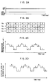
- the rotating speeds Ne are detected at each of top dead centers (TDC), preferably at each of top dead centers (TDC) following each explosion stroke E, so that the rotational speed increment produced by the explosion stroke of a respective cylinder is detected within the time period between the end of an explosion stroke and the beginning of the next subsequent explosion stroke.
- Figs. 2C and 2D the axes of abscissas represent time (ms).
- the strokes of the respective cylinders change successively, in acccordance with time, in the order of a first cylinder (No. 1), a third cylinder (No. 3), a fourth cylinder (No. 4), and a second cylinder (No. 2).
- "I” denotes an ignition stroke
- "A” an intake stroke
- E an explosion stroke
- J a fuel injection stroke.
- the mean effective pressures Pi of the respective cylinders are different from one another in each of cylinders.
- the mean effective pressure Pi is the highest in the fourth cylinder and the lowest in the first cylinder.
- the rotating speeds Ne of the engine are different from one another in each of cylinders.
- the rotating speed Ne is the highest at an explosion stroke of the fourth cylinder and the lowest at an explosion stroke of the first cylinder.
- the mean effective pressures Pi in the respective cylinders which directly influence combustion conditions of the engine, are generally different in each of the cylinders, and the mean effective pressure Pi in each cylinder can be estimated by detecting the corresponding rotating speed Ne.
- each of combustion conditions in the cylinders of the multi-cylinder engine can be consequently estimated from the corresponding rotating speed of the engine at an explosion stroke of the cylinders.
- the apparatus and the method of the present invention can produce stable engine power by detecting the rotating speeds of the multi-cylinder engine at an explosion stroke of respective cylinders, estimating the combustion conditions of the respective cylinders, and controlling the ignition timings or amounts of supplying fuel, so that the respective cylinders have the uniform combustion condition, thereby suppressing vibration caused by unbalanced combustion conditions of the cylinders.
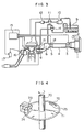
- a fuel injection system of a multi-cylinder engine is schematically illustrated.
- Air introduced from an inlet 2 of an air cleaner 1 passes through a filter of this air cleaner 1 to flow through a hot-wire air flowmeter 3 for detecting an intake amount of air, and further passes through a duct 4 located downstream of the air flowmeter and a throttle body 5 including a restrictor (throttle valve) for regulating the intake air amount, so as to flow into a so-called collector 6.
- the intake air is distributed to intake pipes 8 which are connected to the respective cylinders of the multi-cylinder engine 7 and, then, is drawn into the respective cylinders of the engine.
- fuel is absorbed from a fuel tank 9 and pressurized by a fuel pump 10. Then, the fuel is directed to fuel inlets of fuel injection valves 13 through a fuel damper 11 and a fuel filter 12. Besides, a small percentage of the fuel directed through the fuel filter 12 to the fuel injection valves 13 is drawn into a fuel pressure regulator 14 and, then, is returned to the fuel tank 9. Owing to the function of this fuel regulator, the pressure of the pressurized fuel supplied to the fuel injection valves 13 is regulated to be constant, and such fuel is injected through the fuel injection valves 13 into the intake pipes 8. In this embodiment, as clearly seen in Fig.
- the fuel injection valves 13 are attached adjacently to air inlet ports of the cylinders (on the walls of the intake pipes 8) so as to constitute a so-called MPI (multi-point injection) system, in which a plurality of cylinders of a multi-cylinder engine are independently provided with fuel injection valves for controlling amounts of fuel supplied to the respective cylinders.
- MPI multi-point injection
- the multi-cylinder engine control method and its electronic control apparatus according to the present invention are not necessarily restricted only for this MPI system, and as easily understood from the following explanation, a so-called SPI (single-point injection) system for supplying fuel through a single fuel injection valve to a plurality of cylinders is also applicable if it is able to control the fuel supplied to the respective cylinders.
- An electric signal representing the intake air amount which is output from the air flowmeter 3 is input to a control unit, which will be described in detail below.
- the throttle body 5 is provided with a so-called throttle sensor 18 for detecting an opening degree of the throttle valve, and an output signal from this throttle sensor 18 is likewise input to the control unit 15.
- a distributor 16 is set adjacently to the engine 7 (on the left side of the engine 7, as seen in the drawing), including therewithin a crank angle sensor for detecting a crank rotation angle of the engine.
- This crank angle sensor is so arranged that a metallic disk 71 attached on a crank shaft 70 of the engine 7 is formed with small apertures 72 at intervals of a predetermined angle, and that a light emitting element 73 and a light receiving element 74 are respectively located above and below the metallic disk 71, so as to produce an output signal in proportion with the rotation angle of the crank shaft 70.
- the metallic disk 71 of the crank angle sensor is formed with holes 75, whose diameter is larger than that of the small apertures 72, at locations corresponding to predetermined angles of the crank shaft 70, so that the crank angle sensor is arranged to produce a reference position signal for indicating a reference position of the rotation angle as well as the above-mentioned signal for indicating the rotation angle of the crank shaft, these output signals being also input to the control unit 15.
- a water temperature sensor for detecting a temperature of the engine, an oxygen sensor for detecting an oxygen content of emission gas, and the like are installed, although they are not denoted by reference numerals in Fig. 3.
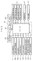
- the control unit 15 Upon receiving the signals for indicating a running condition of the engine which have been output from the various sensors described above, the control unit 15 makes an operation of these signals in predetermined computing processes and drives actuaters of some kinds for suitably controlling the running condition of the engine. For example, as shown in Fig. 3, this control unit 15 outputs control signals to control functions of a power transistor attached on the side of an ignition coil 17, whose connection/disconnection serves to supply/regulate high voltage for ignition to the respective cylinders, functions of the fuel injection valves 13 for injecting/supplying the fuel to the cylinders of the engine 7 and functions of the fuel pump 10.
- the control unit 15 includes a multi-processor unit (MPU) 151, a rewritable nonvolatile memory (EP-ROM) 152, a random access memory (RAM) 153, an LSI circuit part or I/O LSI 154 serving as an input/output circuit, to which the signals detected by the various sensors for indicating the engine running condition are input, and from which the control signals for driving the actuaters are output or the like.
- MPU multi-processor unit
- EP-ROM rewritable nonvolatile memory
- RAM random access memory
- I/O LSI 154 serving as an input/output circuit, to which the signals detected by the various sensors for indicating the engine running condition are input, and from which the control signals for driving the actuaters are output or the like.
- the output signals from an air flowmeter 3, a crank angle sensor 155, an idle switch 156, a starter switch 157, an oxygen sensor 158, a water temperature sensor 159, a battery voltage sensor 160, and a throttle sensor 18 are input to the I/O LSI 154 by way of an A-D converter contained within or provided outside this I/O LSI, if necessary.
- the predetermined computing processes are effected by the MPU 151, the EP-ROM 152, and the RAM 153, and then the operations of the actuaters for controlling the engine such as the fuel injection valves 13, the power transistor of the ignition coil 17, and the fuel pump 10 are controlled.
- a routine illustrated below is performed when discrimination of the cylinders is finished. More particularly, the routine is done at intervals of 180 degrees in a case of the four-cylinder engine. In addition, if the control method in accordance with the present invention is applied to a six-cylinder engine, the routine is performed at intervals of 120 degrees, and if it is further applied to an eight-cylinder engine, the routine is performed at intervals of 90 degrees. Besides, the number of counters CNT for judging suspected values is the same as that of the cylinders, and they are correspondingly assigned to the respective cylinders so as to separately carry out the operation.
- Step 200 of Fig. 1 a rotating speed N obtained from the output signal from the crank angle sensor 155 and a reference ignition timing IGNM and a reference fuel injection pulse width TIM are read and stored.
- IGNM and TIM are read from a memory map stored within the ROM on the basis of the rotating speed and the output signal from the air flowmeter 3.
- Steps 202 and 203 serve to compare the rotating speed N, i.e., the rotating speed of the engine at an explosion stroke of the coresponding cylinder with the average NAV n of the rotating speed of the engine at explosion strokes of all the cylinders.
- N the rotating speed of the engine at an explosion stroke of the coresponding cylinder
- NAV n the average NAV n of the rotating speed of the engine at explosion strokes of all the cylinders.
- Step 204 serves to judge a magnitude of cylinder output from the corresponding cylinder according to the deviation ⁇ N, or particularly to compare this deviation ⁇ N with a predetermined value DN. Then, if ⁇ N is judged to be smaller than DN ( ⁇ N ⁇ DN), the cylinder output from the corresponding cylinder is consequently judged to be normal in comparison with cylinder output from the other cylinders (i.e., average output), and the routine is completed at this step.
- Step 205 is chosen when the deviation ⁇ N is negative, its operation is equivalent to that of Step 204.
- Step 204 if ⁇ N is judged to be larger than DN ( ⁇ N > DN), or in Step 205, if - ⁇ N is judged to be smaller than -DN (- ⁇ N ⁇ -DN), the process proceeds to Step 206 or 207, where the suspected value judging counter CNT exhibits increment (Step 206) or decrement (Step 207). After that, the process proceeds to Step 208, where an absolute value of the suspected value judging counter CNT is judged to be larger or smaller than a predetermined value DNG.
- Step 208 serves to determine authenticity (reliability) of the suspected value of combustion in the corresponding cylinder which is detected above, and if the absolute value of the counter CNT is larger than DNG, the combustion condition of the cylinder in question is judged to be abnormal, thereby proceeding to Steps 209 and 210. On the contrary, if CNT is smaller than DNG, the suspected value is not clearly judged to be true nor false, and the routine is completed at this step.
- Step 208 when the combustion condition of the corresponding cylinder is judged to be abnormal, the process proceeds to step 209 as previously described, where the cylinder, of which abnormality of the combustion condition has been detected, is subjected to correction of a ratio of the fuel to be supplied next and the intake air, i.e., A/F ratio, so that the cylinder in question at the next routine is controlled to have the same combustion condition as the other cylinders. More concretely, by utilizing relationship between a counter value CNT (the axis of abscissas) and an amount for correction ⁇ Te (the axis of ordinates) as shown in Fig. 6, ⁇ Te corresponding to CNT obtained above is computed.
- CNT the axis of abscissas
- ⁇ Te the axis of ordinates
- Step 210 correction of the next ignition timing of the corresponding cylinder is performed in the same manner as Step 209 mentioned above.
- this correction of the ignition timing is conducted by deriving an ignition timing correction amount ⁇ IGN from relationship shown in Fig. 7 according to the counter value CNT described above, so that the ignition timing IGN is determined from the following formula (4) by using this correction amount ⁇ IGN:
- IGN IGNM + ⁇ IGN
- IGNM represents the reference ignition timing.
- this correction of the A/F ratio or the ignition timing according to the counter value CNT representing abnormality of the combustion condition is generally carried out in such a manner that the mean effective pressure Pi of each cylinders is decreased by modifying the A/F ratio to be leaner or smaller than an optimum value of 14.7 or by controlling the ignition timing from an advance timing to a delayed timing.
- the A/F ratio thereof when one of the cylinders exhibits a larger value of the mean effective pressure Pi than those in the other cylinders, the A/F ratio thereof is modified to be smaller, or the ignition timing thereof is delayed, and on the contrary, when one of the cylinders exhibits a smaller value of the mean effective pressure Pi than those in the other cylinders, the A/F ratio thereof is modified to be richer or larger, or the ignition timing thereof is advanced, so that the respective cylinders of the multicylinder engine can have uniform output for stabilizing the engine power.
- the correction amount ⁇ Te of the fuel injection time and the correction amount ⁇ IGN of the ignition timing are expressed by two sets of lines (one is of solid lines and the other is of dashed lines) corresponding to two divided regions of the engine running condition, i.e., a region of idling where a neutral switch is on and a region of driving where the neutral switch is off, and these values are written in the memories in advance.
- Such division of the engine running condition is conducted to further increase stability of the engine power in each of the regions.
- Fig. 10 shows the operational regions of the two kinds of characteristic curves illustrated in Figs. 6 and 7.
- Ne detected from the respective cylinders are processed to be averaged into the mean value NAV n , and the deviation ⁇ N from N at the present routine is calculated (see Fig. 11E).
- the deviation ⁇ N can be also derived by a preset target value in place of the mean value.
- this deviation ⁇ N is judged to be larger or smaller than the predetermined value DN, and if it is larger, the combustion condition of the cylinder in question is judged to be abnormal, so that the fuel injection time Ti (i.e., A/F ratio) or an advance amount of ignition timing ADV is regulated to define the rotating speeds Ne of the respective cylinders within a certain range, as illustrated in Figs. 11A and 11B.
- the fuel injection time Ti i.e., A/F ratio
- ADV advance amount of ignition timing
- FIG. 12B shows measurements of fluctuation of output power from a four-cylinder engine actually installed in a vehicle according to the above-described control method of the present invention, where the fluctuation of the rotating speeds Ne is found to be obviously smaller than that of measurements of output power from an engine in a case of the conventional control method which are comparatively shown in Fig. 12A, so that the stabilization of the output power can be fully effected.
- the maximum fluctuation of the measured rotating speeds is 60 rpm in the conventional case of Fig. 12A, but according to the present invention, it can be reduced to 35 rpm, almost half of the conventional value.
- control method of the present invention can be also very effective for stabilizing the speeds of the cylinders during idling in particular. It is because the engine is influenced by almost no load during idling so that vibration due to the unbalanced output power from the engine cylinders is likely to be felt relatively large, but that the balance of output power of the respective cylinder can be easily obtained by regulating the ignition timing or the supplying fuel.
- the present invention does not particularly require additional sensors so as to be superior in economy, and intends to provide the multi-cylinder engine control method and its electronic control apparatus, by which the unbalanced output power from the respective cylinders of the engine can be regulated to ensure the stable engine power.
Landscapes
- Engineering & Computer Science (AREA)
- Chemical & Material Sciences (AREA)
- Combustion & Propulsion (AREA)
- Mechanical Engineering (AREA)
- General Engineering & Computer Science (AREA)
- Signal Processing (AREA)
- Theoretical Computer Science (AREA)
- Electrical Control Of Ignition Timing (AREA)
- Combined Controls Of Internal Combustion Engines (AREA)
- Electrical Control Of Air Or Fuel Supplied To Internal-Combustion Engine (AREA)
Claims (9)
- Verfahren zur Steuerung eines mehrzylindrigen Motors, mit dem Schritt des Erfassens der Drehzahl N des Motors (7) im Arbeitstakt der jeweiligen Zylinder des Motors (7),
gekennzeichnet durch die folgenden Schritte:(A) Bestimmen des Verbrennungsdrucks in den jeweiligen Motorzylindern auf der Grundlage der erfaßten Drehzahl N,(B) Bestimmen einer Abweichung des Verbrennungsdrucks anhand des im Schritt (A) bestimmten Verbrennungsdrucks,(C) Vergleichen der ermittelten Abweichung mit einem vorbestimmten Referenzwert,(D) Zählen, wie oft die Abweichung den vorbestimmten Referenzwert überschreitet, und(E) Steuern des jeweiligen Zylinders oder der Zylinder des Motors danach, wie oft die Abweichung den vorbestimmten Referenzwert überschreitet. - Verfahren nach Anspruch 1,
dadurch gekennzeichnet, daß
die Abweichungen der Verbrennungsdrücke in den jeweiligen Zylindern ermittelt werden, indem die geschätzten Verbrennungsdrücke in den jeweiligen Zylindern gemittelt werden und der gemittelte Druckwert mit den geschätzten Verbrennungsdrücken in den jeweiligen Zylindern verglichen wird. - Verfahren nach Anspruch 1,
dadurch gekennzeichnet, daß
die Abweichungen der Verbrennungsdrücke in den jeweiligen Zylindern ermittelt werden, indem die geschätzten Verbrennungsdrücke in den jeweiligen Zylindern mit einem vorbestimmten Wert verglichen werden. - Verfahren nach einem der Ansprüche 1 bis 3,
dadurch gekennzeichnet, daß
der jeweilige Zylinder bzw. die Zylinder des Motors gesteuert werden, indem der Zündzeitpunkt und/oder die Kraftstoffmenge eingestellt werden. - Vorrichtung zur Steuerung eines mehrzylindrigen Motors, mit Drehzahlsensoren (70-75, 155) zur Erfassung der Drehzahl N des Motors (7) während des Arbeitstakts, sowie mit einer elektronischen Steuerungseinrichtung (15) zur Steuerung der Zylinder des Motors (7) nach Maßgabe der erfaßten Drehzahl N,
dadurch gekennzeichnet, daß
die elektronische Steuerung zur Einrichtung (15) aufweist(A) eine Einrichtung zur Bestimmung des Verbrennungsdrucks in den jeweiligen Motorzylindern auf der Grundlage der erfaßten Drehzahl N,(B) eine Einrichtung zur Bestimmung einer Abweichung des Verbrennungsdrucks anhand des im Schritt (A) bestimmten Verbrennungsdrucks,(C) eine Einrichtung zum Vergleichen der ermittelten Abweichung mit einem vorbestimmten Referenzwert,(D) eine Einrichtung zum Zählen, wie oft die Abweichung den vorbestimmten Referenzwert überschreitet, und(E) eine Steuerung des oder der jeweiligen Zylinder des Motors danach, wie oft die Abweichung den vorbestimmten Referenzwert überschreitet. - Vorrichtung nach Anspruch 5,
dadurch gekennzeichnet, daß
die elektronische Steuerungseinrichtung (15) außerdem eine Einrichtung zum Mitteln der geschätzten Verbrennungsdrücke in den jeweiligen Zylindern aufweist, und daß die Berechnungseinrichtung zur Berechnung der Abweichungen der Verbrennungsdrücke in der elektronischen Steuerungseinrichtung (15) eine Vergleichseinrichtung aufweist, um die Verbrennungsdrücke in den jeweiligen Zylindern mit dem Mittelwert zu vergleichen, um die Abweichungen zu erhalten. - Vorrichtung nach Anspruch 5,
dadurch gekennzeichnet, daß
die elektronische Steuerungseinrichtung (15) eine Einrichtung zur Erzeugung eines vorbestimmten Referenzwerts für den Verbrennungsdruck aufweist, und daß die Berechnungseinrichtung zur Berechnung der Abweichungen der Verbrennungsdrücke eine Vergleichseinrichtung hat, um die Verbrennungsdrücke der jeweiligen Zylinder mit dem Referenzwert zu vergleichen, um die Abweichungen zu ermitteln. - Vorrichtung nach zumindest einem der Ansprüche 5 bis 7,
dadurch gekennzeichnet, daß
die Vorrichtung außerdem eine Einrichtung (156) zur Erfassung von Betriebszuständen des Motors während des Leerlaufs aufweist. - Vorrichtung nach zumindest einem der Ansprüche 5 bis 8,
dadurch gekennzeichnet, daß
die elektronische Steuerungseinrichtung (15) den oder die jeweiligen Zylinder des Motors durch Einstellen des Zündzeitpunkts und/oder der Kraftstoffmenge steuert.
Applications Claiming Priority (2)
| Application Number | Priority Date | Filing Date | Title |
|---|---|---|---|
| JP259479/88 | 1988-10-17 | ||
| JP63259479A JPH0737789B2 (ja) | 1988-10-17 | 1988-10-17 | 複数気筒エンジンの電子式制御装置 |
Publications (3)
| Publication Number | Publication Date |
|---|---|
| EP0364959A2 EP0364959A2 (de) | 1990-04-25 |
| EP0364959A3 EP0364959A3 (de) | 1991-04-03 |
| EP0364959B1 true EP0364959B1 (de) | 1995-07-19 |
Family
ID=17334652
Family Applications (1)
| Application Number | Title | Priority Date | Filing Date |
|---|---|---|---|
| EP89119268A Expired - Lifetime EP0364959B1 (de) | 1988-10-17 | 1989-10-17 | Verfahren und Vorrichtung zur elektronischen Steuerung einer Maschine mit mehreren Zylindern |
Country Status (5)
| Country | Link |
|---|---|
| US (1) | US5069183A (de) |
| EP (1) | EP0364959B1 (de) |
| JP (1) | JPH0737789B2 (de) |
| KR (1) | KR910008267A (de) |
| DE (1) | DE68923526T2 (de) |
Families Citing this family (38)
| Publication number | Priority date | Publication date | Assignee | Title |
|---|---|---|---|---|
| EP0433690B1 (de) * | 1989-11-22 | 1994-12-28 | Unisia Jecs Corporation | Verfahren und Vorrichtung zur Erkennung von Fehlzündung in einem Zylinder einer Brennkraftmaschine |
| DE69125194T2 (de) * | 1990-01-09 | 1997-07-17 | Atsugi Unisia Corp | Verfahren und Vorrichtung zur Detektierung eines Verbrennungsdefekts in einem Zylinder einer inneren Brennkraftmaschine |
| EP0442687B1 (de) * | 1990-02-14 | 1998-04-15 | Lucas Industries Public Limited Company | Vorrichtung zur Detektierung von Fehlzündungen |
| KR940004352B1 (ko) * | 1990-10-02 | 1994-05-23 | 미쓰비시덴키가부시키가이샤 | 내연기관의 녹제어장치 |
| US5287735A (en) * | 1990-12-10 | 1994-02-22 | Sensortech L.P. | Engine misfire or roughness detection method and apparatus |
| JP2715207B2 (ja) * | 1992-01-16 | 1998-02-18 | 株式会社ユニシアジェックス | 内燃機関の電子制御燃料供給装置 |
| DE4232204C2 (de) * | 1992-09-25 | 1995-11-02 | Siemens Ag | Verfahren zur Unterdrückung von Schwingungen im Antriebsstrang eines Kraftfahrzeugs |
| DE4414727B4 (de) * | 1993-04-27 | 2004-01-29 | Hitachi, Ltd. | Steuerverfahren und Steuereinheit für Mehrzylinder-Brennkraftmaschinen |
| DE4447846B4 (de) * | 1993-04-27 | 2006-06-14 | Hitachi, Ltd. | Verfahren und Vorrichtung zum Steuern einer Brennkraftmaschine |
| JP2829698B2 (ja) * | 1993-10-19 | 1998-11-25 | 株式会社ユニシアジェックス | 内燃機関の燃焼状態検出装置 |
| JP3323974B2 (ja) * | 1995-02-24 | 2002-09-09 | 株式会社ユニシアジェックス | 内燃機関の制御装置 |
| US5957994A (en) * | 1996-08-12 | 1999-09-28 | Ford Global Technologies, Inc. | Method for improving spark ignited internal combustion engine acceleration and idling in the presence of poor driveability fuels |
| US6230683B1 (en) | 1997-08-22 | 2001-05-15 | Cummins Engine Company, Inc. | Premixed charge compression ignition engine with optimal combustion control |
| AU4082997A (en) | 1996-08-23 | 1998-03-26 | Cummins Engine Company Inc. | Homogeneous charge compression ignition engine with optimal combustion control |
| DE19700711C2 (de) * | 1997-01-10 | 1999-05-12 | Siemens Ag | Verfahren zum Ausgleich des systematischen Fehlers an Einspritzvorrichtungen für eine Brennkraftmaschine |
| DE19739085A1 (de) | 1997-09-06 | 1999-03-11 | Bosch Gmbh Robert | Verfahren zur Steuerung und Regelung der Verbrennung im Brennraum einer Brennkraftmaschine |
| CN1292153C (zh) | 1998-02-23 | 2006-12-27 | 卡明斯发动机公司 | 带有优化燃烧控制的预混合充量压缩点火发动机 |
| US6032617A (en) * | 1998-05-27 | 2000-03-07 | Caterpillar Inc. | Dual fuel engine which ignites a homogeneous mixture of gaseous fuel, air, and pilot fuel |
| US6209520B1 (en) * | 1999-06-15 | 2001-04-03 | Ilya V. Kolmanovsky | Method and apparatus for cylinder balancing |
| US6516780B2 (en) * | 2000-11-13 | 2003-02-11 | Siemens Vdo Automotive Corporation | System and method for optimizing engine performance |
| US6516253B2 (en) | 2000-12-05 | 2003-02-04 | Ford Global Technologies, Inc. | Engine ready detection using crankshaft speed feedback |
| US6542798B2 (en) | 2000-12-06 | 2003-04-01 | Ford Global Technologies, Inc. | Engine ready signal using peak engine cylinder pressure detection |
| US6598468B2 (en) | 2001-07-11 | 2003-07-29 | Cummins Inc. | Apparatus and methods for determining start of combustion for an internal combustion engine |
| KR100440129B1 (ko) * | 2001-11-22 | 2004-07-12 | 현대자동차주식회사 | 차량의 엔진 제어장치 및 방법 |
| KR20030050141A (ko) * | 2001-12-18 | 2003-06-25 | 현대자동차주식회사 | 디젤 엔진의 연료 분사량 보정장치 및 방법 |
| KR100427267B1 (ko) * | 2001-12-18 | 2004-04-14 | 현대자동차주식회사 | 차량의 엔진 공회전 제어방법 |
| DE102004046086A1 (de) * | 2004-09-23 | 2006-03-30 | Robert Bosch Gmbh | Verfahren und Vorrichtung zur Steuerung einer Brennkraftmaschine |
| CN101213368A (zh) * | 2005-07-01 | 2008-07-02 | 百佳车辆有限公司 | 用于控制发动机噪声的方法及系统 |
| DE102006026640A1 (de) * | 2006-06-08 | 2007-12-13 | Robert Bosch Gmbh | Verfahren zum Betreiben einer Brennkraftmaschine |
| AT503739B1 (de) * | 2007-09-13 | 2009-07-15 | Avl List Gmbh | Verfahren zur regelung der verbrennungslage bei einer brennkraftmaschine |
| WO2011084866A2 (en) | 2010-01-07 | 2011-07-14 | Dresser-Rand Company | Exhaust catalyst pre-heating system and method |
| JP5120468B2 (ja) * | 2011-01-11 | 2013-01-16 | トヨタ自動車株式会社 | 多気筒内燃機関の異常判定装置 |
| JP5303608B2 (ja) * | 2011-06-17 | 2013-10-02 | 日立オートモティブシステムズ株式会社 | 火花点火式多気筒エンジンの燃焼制御装置 |
| KR101628106B1 (ko) | 2014-10-20 | 2016-06-08 | 현대자동차 주식회사 | 연소압 센서를 이용한 엔진 제어 방법 및 시스템 |
| JP6536223B2 (ja) * | 2015-06-30 | 2019-07-03 | いすゞ自動車株式会社 | 筒内圧力推定方法及びそれに基づく筒内圧力制御方法 |
| US20170138288A1 (en) * | 2015-11-13 | 2017-05-18 | General Electric Company | System for monitoring internal pressure of engine combustion chambers |
| US10731582B2 (en) * | 2016-11-16 | 2020-08-04 | GM Global Technology Operations LLC | Determination of engine parameter based on determining a metric over three or more cylinder combustion cycles |
| GB2578155B (en) * | 2018-10-19 | 2021-01-13 | Delphi Automotive Systems Lux | Method of controlling vehicle emissions |
Family Cites Families (9)
| Publication number | Priority date | Publication date | Assignee | Title |
|---|---|---|---|---|
| US4461257A (en) * | 1980-03-28 | 1984-07-24 | Nissan Motor Company, Limited | Method and system for controlling engine ignition timing |
| JPS5851243A (ja) * | 1981-09-24 | 1983-03-25 | Nippon Denso Co Ltd | 内燃機関の燃焼状態検出方法 |
| JPS58131362A (ja) * | 1982-01-29 | 1983-08-05 | Nippon Denso Co Ltd | エンジン回転速度制御方法 |
| JPS58176470A (ja) * | 1982-04-08 | 1983-10-15 | Toyota Motor Corp | アイドリング時のエンジン回転数制御方法 |
| US4495920A (en) * | 1982-04-09 | 1985-01-29 | Nippondenso Co., Ltd. | Engine control system and method for minimizing cylinder-to-cylinder speed variations |
| JPS61212644A (ja) * | 1985-03-19 | 1986-09-20 | Diesel Kiki Co Ltd | 内燃機関用アイドル運転制御装置 |
| US4697561A (en) * | 1985-04-15 | 1987-10-06 | Purdue Research Foundation | On-line engine torque and torque fluctuation measurement for engine control utilizing crankshaft speed fluctuations |
| JP2556964B2 (ja) * | 1985-11-14 | 1996-11-27 | 株式会社ゼクセル | 内燃機関用アイドル運転制御装置 |
| DE3871832T2 (de) * | 1987-03-25 | 1993-01-14 | Japan Electronic Control Syst | Vorrichtung zur zuendsteuerung und zur unterdrueckung von stoerschwingungen waehrend des beschleunigens einer brennkraftmaschine. |
-
1988
- 1988-10-17 JP JP63259479A patent/JPH0737789B2/ja not_active Expired - Fee Related
-
1989
- 1989-10-12 US US07/420,519 patent/US5069183A/en not_active Expired - Lifetime
- 1989-10-17 DE DE68923526T patent/DE68923526T2/de not_active Expired - Fee Related
- 1989-10-17 KR KR1019890014894A patent/KR910008267A/ko not_active Withdrawn
- 1989-10-17 EP EP89119268A patent/EP0364959B1/de not_active Expired - Lifetime
Also Published As
| Publication number | Publication date |
|---|---|
| DE68923526T2 (de) | 1996-01-18 |
| DE68923526D1 (de) | 1995-08-24 |
| US5069183A (en) | 1991-12-03 |
| EP0364959A3 (de) | 1991-04-03 |
| JPH02108860A (ja) | 1990-04-20 |
| KR910008267A (ko) | 1991-05-31 |
| EP0364959A2 (de) | 1990-04-25 |
| JPH0737789B2 (ja) | 1995-04-26 |
Similar Documents
| Publication | Publication Date | Title |
|---|---|---|
| EP0364959B1 (de) | Verfahren und Vorrichtung zur elektronischen Steuerung einer Maschine mit mehreren Zylindern | |
| US6694960B2 (en) | Method and arrangement for determining cylinder-individual differences of a control variable in a multi-cylinder internal combustion engine | |
| US5016591A (en) | System and method for controlling a combustion state in a multi-cylinder engine for a vehicle | |
| US5058550A (en) | Method for determining the control values of a multicylinder internal combustion engine and apparatus therefor | |
| JPWO2003006808A1 (ja) | 4ストロークエンジンの制御装置及び制御方法 | |
| US4725954A (en) | Apparatus and method for controlling fuel supply to internal combustion engine | |
| JPH0814271B2 (ja) | 内燃機関の点火時期制御装置 | |
| US7448360B2 (en) | Controller of internal combustion engine | |
| US6975934B2 (en) | Control system for correcting a torque variation of an engine | |
| JPH08200115A (ja) | エンジンの燃焼制御装置 | |
| JPH01106958A (ja) | 可変圧縮比型内燃機関の制御装置 | |
| JPS61185642A (ja) | 内燃機関の燃料噴射時期制御装置 | |
| GB2366004A (en) | A method for diagnosing cylinder bank dependant or cylinder bank independent faults in an internal combustion engine | |
| JPH10141097A (ja) | 内燃機関の制御装置、バルブタイミング制御装置及びバルブタイミング制御方法 | |
| JP2000120488A (ja) | 失火検出装置 | |
| JPH08151951A (ja) | 内燃機関のノッキング制御装置 | |
| JPH0842434A (ja) | 内燃機関の点火時期制御装置 | |
| JPH03172554A (ja) | エンジンの出力制御方法 | |
| JP7643298B2 (ja) | 燃料噴射量制御装置 | |
| US7140351B2 (en) | Method and device for operating an internal combustion engine | |
| GB2142164A (en) | Fuel supply control method for internal combustion engines capable of improving acceleration of the engine from an idling region therof | |
| JP2000179381A (ja) | 可変バルブタイミング機構付き内燃機関の制御装置 | |
| JPS6316153A (ja) | エンジンの制御装置 | |
| JPS61123727A (ja) | 内燃機関の燃料噴射量制御装置 | |
| JPH0517401Y2 (de) |
Legal Events
| Date | Code | Title | Description |
|---|---|---|---|
| PUAI | Public reference made under article 153(3) epc to a published international application that has entered the european phase |
Free format text: ORIGINAL CODE: 0009012 |
|
| AK | Designated contracting states |
Kind code of ref document: A2 Designated state(s): DE FR GB |
|
| 17P | Request for examination filed |
Effective date: 19901122 |
|
| PUAL | Search report despatched |
Free format text: ORIGINAL CODE: 0009013 |
|
| AK | Designated contracting states |
Kind code of ref document: A3 Designated state(s): DE FR GB |
|
| 17Q | First examination report despatched |
Effective date: 19940128 |
|
| GRAA | (expected) grant |
Free format text: ORIGINAL CODE: 0009210 |
|
| AK | Designated contracting states |
Kind code of ref document: B1 Designated state(s): DE FR GB |
|
| REF | Corresponds to: |
Ref document number: 68923526 Country of ref document: DE Date of ref document: 19950824 |
|
| ET | Fr: translation filed | ||
| PLBE | No opposition filed within time limit |
Free format text: ORIGINAL CODE: 0009261 |
|
| STAA | Information on the status of an ep patent application or granted ep patent |
Free format text: STATUS: NO OPPOSITION FILED WITHIN TIME LIMIT |
|
| 26N | No opposition filed | ||
| REG | Reference to a national code |
Ref country code: GB Ref legal event code: IF02 |
|
| PGFP | Annual fee paid to national office [announced via postgrant information from national office to epo] |
Ref country code: FR Payment date: 20030923 Year of fee payment: 15 |
|
| PGFP | Annual fee paid to national office [announced via postgrant information from national office to epo] |
Ref country code: GB Payment date: 20030924 Year of fee payment: 15 |
|
| PG25 | Lapsed in a contracting state [announced via postgrant information from national office to epo] |
Ref country code: GB Free format text: LAPSE BECAUSE OF NON-PAYMENT OF DUE FEES Effective date: 20041017 |
|
| PGFP | Annual fee paid to national office [announced via postgrant information from national office to epo] |
Ref country code: DE Payment date: 20041206 Year of fee payment: 16 |
|
| GBPC | Gb: european patent ceased through non-payment of renewal fee |
Effective date: 20041017 |
|
| PG25 | Lapsed in a contracting state [announced via postgrant information from national office to epo] |
Ref country code: FR Free format text: LAPSE BECAUSE OF NON-PAYMENT OF DUE FEES Effective date: 20050630 |
|
| REG | Reference to a national code |
Ref country code: FR Ref legal event code: ST |
|
| PG25 | Lapsed in a contracting state [announced via postgrant information from national office to epo] |
Ref country code: DE Free format text: LAPSE BECAUSE OF NON-PAYMENT OF DUE FEES Effective date: 20060503 |