EP0365470B1 - Dispositif de raccordement de l'extrémité terminale d'une bande avec le début d'une autre bande - Google Patents
Dispositif de raccordement de l'extrémité terminale d'une bande avec le début d'une autre bande Download PDFInfo
- Publication number
- EP0365470B1 EP0365470B1 EP89810699A EP89810699A EP0365470B1 EP 0365470 B1 EP0365470 B1 EP 0365470B1 EP 89810699 A EP89810699 A EP 89810699A EP 89810699 A EP89810699 A EP 89810699A EP 0365470 B1 EP0365470 B1 EP 0365470B1
- Authority
- EP
- European Patent Office
- Prior art keywords
- web
- servomechanism
- signal
- drive
- output signal
- Prior art date
- Legal status (The legal status is an assumption and is not a legal conclusion. Google has not performed a legal analysis and makes no representation as to the accuracy of the status listed.)
- Expired - Lifetime
Links
- 238000000034 method Methods 0.000 claims description 10
- 230000009467 reduction Effects 0.000 claims description 5
- 230000008569 process Effects 0.000 claims description 4
- 230000007246 mechanism Effects 0.000 claims description 3
- 230000003287 optical effect Effects 0.000 claims description 2
- 238000010586 diagram Methods 0.000 description 8
- 238000004806 packaging method and process Methods 0.000 description 4
- 230000010354 integration Effects 0.000 description 3
- 230000008859 change Effects 0.000 description 2
- 238000006073 displacement reaction Methods 0.000 description 2
- 230000010363 phase shift Effects 0.000 description 2
- 230000008901 benefit Effects 0.000 description 1
- 239000003990 capacitor Substances 0.000 description 1
- 230000001419 dependent effect Effects 0.000 description 1
- 230000003993 interaction Effects 0.000 description 1
- 239000012528 membrane Substances 0.000 description 1
- 238000012544 monitoring process Methods 0.000 description 1
- 238000010606 normalization Methods 0.000 description 1
Images

Classifications
-
- B—PERFORMING OPERATIONS; TRANSPORTING
- B65—CONVEYING; PACKING; STORING; HANDLING THIN OR FILAMENTARY MATERIAL
- B65H—HANDLING THIN OR FILAMENTARY MATERIAL, e.g. SHEETS, WEBS, CABLES
- B65H19/00—Changing the web roll
- B65H19/10—Changing the web roll in unwinding mechanisms or in connection with unwinding operations
- B65H19/18—Attaching, e.g. pasting, the replacement web to the expiring web
- B65H19/1857—Support arrangement of web rolls
- B65H19/1873—Support arrangement of web rolls with two stationary roll supports carrying alternately the replacement and the expiring roll
-
- B—PERFORMING OPERATIONS; TRANSPORTING
- B65—CONVEYING; PACKING; STORING; HANDLING THIN OR FILAMENTARY MATERIAL
- B65H—HANDLING THIN OR FILAMENTARY MATERIAL, e.g. SHEETS, WEBS, CABLES
- B65H19/00—Changing the web roll
- B65H19/10—Changing the web roll in unwinding mechanisms or in connection with unwinding operations
- B65H19/18—Attaching, e.g. pasting, the replacement web to the expiring web
- B65H19/1842—Attaching, e.g. pasting, the replacement web to the expiring web standing splicing, i.e. the expiring web being stationary during splicing contact
- B65H19/1852—Attaching, e.g. pasting, the replacement web to the expiring web standing splicing, i.e. the expiring web being stationary during splicing contact taking place at a distance from the replacement roll
-
- B—PERFORMING OPERATIONS; TRANSPORTING
- B65—CONVEYING; PACKING; STORING; HANDLING THIN OR FILAMENTARY MATERIAL
- B65H—HANDLING THIN OR FILAMENTARY MATERIAL, e.g. SHEETS, WEBS, CABLES
- B65H23/00—Registering, tensioning, smoothing or guiding webs
- B65H23/04—Registering, tensioning, smoothing or guiding webs longitudinally
- B65H23/18—Registering, tensioning, smoothing or guiding webs longitudinally by controlling or regulating the web-advancing mechanism, e.g. mechanism acting on the running web
- B65H23/188—Registering, tensioning, smoothing or guiding webs longitudinally by controlling or regulating the web-advancing mechanism, e.g. mechanism acting on the running web in connection with running-web
- B65H23/1882—Registering, tensioning, smoothing or guiding webs longitudinally by controlling or regulating the web-advancing mechanism, e.g. mechanism acting on the running web in connection with running-web and controlling longitudinal register of web
-
- B—PERFORMING OPERATIONS; TRANSPORTING
- B65—CONVEYING; PACKING; STORING; HANDLING THIN OR FILAMENTARY MATERIAL
- B65H—HANDLING THIN OR FILAMENTARY MATERIAL, e.g. SHEETS, WEBS, CABLES
- B65H2301/00—Handling processes for sheets or webs
- B65H2301/40—Type of handling process
- B65H2301/46—Splicing
- B65H2301/463—Splicing splicing means, i.e. means by which a web end is bound to another web end
- B65H2301/4634—Heat seal splice
Definitions
- the present invention relates to a method for connecting the end of a band to the beginning of another band according to the preamble of claim 1.
- Such a method is known from FR-A-2 078 354.
- This method works with a device which comprises an integrator consisting of an operational amplifier and a capacitor.
- the output of the operational amplifier is connected to the input of a threshold switch which supplies current for a relay which is provided in order to switch off the first drive motor.
- This device can use a buffer device to compensate for the speed differences that the belt has or can have before and after the buffer device.
- a device for feeding a tape which has two buffer devices for the supply rolls. These buffer devices are located in front of the mechanism for connecting both ends of the tape.
- the invention is based on the object of improving a method of the type mentioned at the outset in such a way that a precisely centered splicing is possible, even with high machine output.
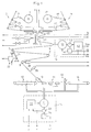
- the packaging machine according to FIG. 1 is provided with a first supply roll 1, from which a tape or a film 2 is unwound, via a roll system 3, a splicing roll 4, a guide roll 5, a drive roll 6, a film storage roll 7 and two further guide rolls 8 and 9 is fed to a folding box 10 by pulling the film 2 formed into a tube through a roller feed 11.
- a loading device 12 In front of the folding box 10 there is a loading device 12, through which the goods to be packaged are introduced into the film tube, which is closed at regular intervals by a transverse heater 13, at the exit of which an outlet device 14 is provided in order to remove the packaged and closed goods.
- the roller feed 11 is driven by the drive or motor 31 of a first servo device 15 and the drive roller 6 by the drive or motor 41 of a second servo device 16 driven.
- the servo devices 15 and 16 are connected to a processor, not shown in the figure. They can be constructed similarly and each have an amplifier 32 or 42, a tachometer 33 or 43 and an angle sensor 34 or 44.
- the packaging machine according to FIG. 1 is also provided with a second supply roll 17, from which a band or a film 18 can be unwound as soon as the supply roll 1 is empty.
- a splicer device 21 is provided, which presses the splicer rollers 4 and 20 against one another in order to connect the end of the film 2 to the beginning of the film 18, and the film storage roller 7 is movably integrated into a device 22 via a rocker arm 71 to be able to change the length of the film loop.
- the packaging machine according to FIG. 1 works as follows:
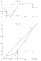
- the film limit switch 23 detects the point in time at which the end of the film 2 passes a specific point on the roller system and supplies a signal a to the processor which, on the basis of this signal and other parameters, generates a control signal Vas for the servo device 16 by the speed v of the motor 41 normalized according to that in FIG. 2 change function v (t) shown.
- This path difference L is taken up by the movable film storage roller 7 because the length of the lower loop becomes shorter by the amount L during the time 0 to 2 ⁇ (FIG. 2) due to the movement of the rocker arm 71.
- the speeds are the two Parts of the film the same.
- the processor performs the following operations:
- p and q are parameters with the dimension s ⁇ 1.
- the processor causes the following operations to be performed:
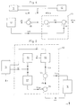
- the sum of the signal da and the output signal V'as of a multiplier 52 is formed in an adding circuit 55, in which the output signals z and v of the circuit 51 and the device 15 are multiplied.
- the output signal Vas of the circuit 55 is fed to the device 16, which also supplies the signal va.
- FIG. 6 shows that the function v (t) is determined at the discretion and the speed v can also be kept equal to zero for a predetermined time GH.
- FIG. 7 the elements 2, 4, 20, 23 and 27 of FIG. 1 are again shown schematically and some marks of the film 2 are numbered 0, 1, 2, ... 10.
- the distance LV between the sensor point A of the membrane switch 23 and the splice point B between the splice rollers 4 and 20 and the distance LM between the point B and the sensor point C of the button 27 is given by the geometry of the system.
- the button 23 therefore recognizes the end of the film at point A and accordingly emits the signal a.
- the button 27 constantly monitors the marks and generates a signal b each time a mark passes.
- the summand LR is chosen at discretion, for example smaller than a brand section.
- the processor first determines the number of entire mark sections on the path x defined in this way, which gives the current position of mark 1; it then calculates both the number of marks up to the start of the speed reduction and the corresponding phase shift of the motor 41, which is done with the aid of the signal va (FIG. 1), as well as the number of marks up to the splice torque and the corresponding phase shift of the motor 41.
- the distance DB corresponds to two and a half mark sections, for example, and the speed reduction begins when the mark 1 passes the point D.
- the splicing moment at which the end of the prepared film 18 (FIG. 1) is connected to the leading end of the old film 2 corresponds to the passage of the mark 1 at point B, at which the speed of the film is zero for a moment .
- the splicing according to this method can also be set such that the trigger length is determined by determining the distance between two centering marks, which can be carried out, for example, by the interaction of an optical button and an incremental encoder, a trigger length corresponding to the centering mark distance.
- first and / or the second motor can be DC servomotors with a tachometer generator and incremental encoder, as well as AC servomotors with a resolver, for example, which are very dynamic and provide information about the absolute angle.
- Other drives can also be used otherwise. It should also be taken into account that the integration, which is carried out by the integrator 49 of the equivalent circuit diagram according to FIG. 4, or the subtraction, which is carried out by the subtractor 48, actually takes place physically in the device 22.
Landscapes
- Replacement Of Web Rolls (AREA)
- Controlling Rewinding, Feeding, Winding, Or Abnormalities Of Webs (AREA)
Claims (9)
- Dispositif pour raccorder l'extrémité d'une bande au début d'une autre bande, comportant un premier dispositif d'entraînement (31) pour la bande (2) déroulée d'un rouleau débiteur (1), un second dispositif d'entraînement (41) pour assister le déplacement de la bande (2), un autre rouleau débiteur (17) pour la bande devant être raccordée, un premier dispositif tampon (22) pour compenser les différences de vitesse, que la bande (2) présente ou peut présenter en amont et en aval du dispositif tampon (22), un intégrateur (49), respectivement un autre dispositif tampon (3,19) pour les rouleaux débiteurs (1;17), et un mécanisme (4,20) pour raccorder les deux extrémités des bandes, ce dispositif étant agencé pour réduire à zéro la vitesse entre les bandes lorsque deux extrémités de bandes doivent être raccordées, caractérisé en ce que le premier dispositif d'entraînement (31) est intégré dans un premier dispositif d'asservissement (15) et le second dispositif d'entraînement (41) est intégré dans un second dispositif d'asservissement (16), par le fait que les deux dispositifs d'asservissement (15;16) sont raccordés à un calculateur, et que le second dispositif d'asservissement (16) reçoit du calculateur un signal de commande Vas, pour lequel dans le fonctionnement normal, c'est-à-dire lorsque les deux extrémités des bandes sont déjà reliées, on a la relation

- Dispositif selon la revendication 1, caractérisé en ce que pour la commande du second dispositif d'asservissement (16) pendant le fonctionnement particulier, c'est-à-dire pendant l'opération de raccordement des deux extrémités des bandes, le calculateur délivre un signal pour lequel la relation

- Dispositif selon la revendication 1 ou 2, caractérisé en ce que le calculateur travaille, dans le fonctionnement normal, conformément à un circuit équivalent, qui possède un circuit de correction de vitesse (51), un circuit de correction de phase (53), un multiplicateur (52), un circuit additionneur (55) et un soustracteur (54), pour exécuter les opérations suivantes :a) un signal d'angle réel wr du premier dispositif d'asservissement (15) est envoyé au circuit de correction de phase (53), dont le signal de sortie Was charge le soustracteur (54) pour former la différence
 b) le signal d'angle réel wr du premier dispositif d'asservissement (15) est également envoyé au circuit de correction de vitesse (51), dont le signal de sortie z est multiplié, dans le multiplicateur (52), par le premier signal de sortie v du premier dispositif d'asservissement (15), pour former un signal de sortie V'as, qui est ajouté au signal da dans le circuit additionneur (55), etc) le signal de sortie Vas du circuit additionneur (55) est envoyé au second dispositif d'asservissement (16) de manière à réduire la vitesse entre les bandes à zéro.
 - Dispositif selon l'une des revendications 1 à 3, caractérisé par le fait que dans le fonctionnement normal, le processeur travaille conformément à un second circuit équivalent pour effectuer les opérations suivantes :a) le signal de sortie v du premier dispositif d'asservissement (15) est envoyé à un premier soustracteur (47), qui forme la différence

 b) l'intégrateur (49) reçoit, à son entrée, le signal de sortie vh d'un troisième soustracteur (48), qui forme le signal de différence
 c) le signal de sortie Vas est utilisé en tant que signal de commande pour le second dispositif d'asservissement (16), pendant le fonctionnement normal.
 - Dispositif selon l'une des revendications 2 à 4, caractérisé par le fait que le premier dispositif tampon (22) est réglé uniquement pendant le fonctionnement normal.
- Dispositif selon l'une des revendications 1 à 5, caractérisé en ce qu'un détecteur de marques (27) est disposé entre le mécanisme (4,20) servant à raccorder les deux extrémités des bandes et un rouleau (6) entraîné par le second dispositif d'entraînement (41).
- Dispositif selon la revendication 6, caractérisé en ce que pour chaque rouleau débiteur (1;17) il est prévu un palpeur (23;24) servant à détecter l'extrémité de la bande respective.
- Dispositif selon la revendication 6, caractérisé en ce qu'au moins un autre palpeur (28,29) est prévu en aval du premier dispositif tampon (22), dans la direction de déplacement de la bande.
- Dispositif selon l'une des revendications 6 à 8, caractérisé en ce que les palpeurs sont des capteurs optiques.
Applications Claiming Priority (2)
| Application Number | Priority Date | Filing Date | Title |
|---|---|---|---|
| CH386788 | 1988-10-17 | ||
| CH3867/88 | 1988-10-17 |
Publications (3)
| Publication Number | Publication Date |
|---|---|
| EP0365470A2 EP0365470A2 (fr) | 1990-04-25 |
| EP0365470A3 EP0365470A3 (fr) | 1991-02-27 |
| EP0365470B1 true EP0365470B1 (fr) | 1996-01-03 |
Family
ID=4265193
Family Applications (1)
| Application Number | Title | Priority Date | Filing Date |
|---|---|---|---|
| EP89810699A Expired - Lifetime EP0365470B1 (fr) | 1988-10-17 | 1989-09-18 | Dispositif de raccordement de l'extrémité terminale d'une bande avec le début d'une autre bande |
Country Status (4)
| Country | Link |
|---|---|
| US (1) | US5045134A (fr) |
| EP (1) | EP0365470B1 (fr) |
| JP (1) | JP2855142B2 (fr) |
| DE (1) | DE58909555D1 (fr) |
Families Citing this family (42)
| Publication number | Priority date | Publication date | Assignee | Title |
|---|---|---|---|---|
| FR2655888A1 (fr) * | 1989-12-20 | 1991-06-21 | Prosys | Devidoir a regulation de tension du fil pour alimenter une bobineuse a partir d'une nourrice. |
| JPH0678139B2 (ja) * | 1990-04-13 | 1994-10-05 | エス・ケイエンジニアリング株式会社 | ウェブ自動継ぎ装置 |
| JPH0623877A (ja) * | 1991-05-30 | 1994-02-01 | Totani Giken Kogyo Kk | プラスチックフィルム送り装置 |
| US5252170A (en) * | 1991-07-11 | 1993-10-12 | Shibuya International, Inc. | Web splicing apparatus |
| IT1253282B (it) * | 1991-10-16 | 1995-07-14 | Gd Spa | Dispositivo per la giunzione automatica di nastrini di ridotte dimensioni trasversali |
| DE59302791D1 (de) * | 1992-03-30 | 1996-07-11 | Meteor Ag | Vorrichtung und Verfahren zur Spannungsregulierung eines fadenförmigen Gutes, vorzugsweise eines Wickeldrahtes für elektrische Spulen |
| US5269859A (en) * | 1992-05-18 | 1993-12-14 | Sherry Donald E | Method of measuring length of lap joint between two sheets of material |
| US5356496A (en) * | 1992-06-15 | 1994-10-18 | The Black Clawson Company | Splice tail tape-down method and apparatus |
| US5643395A (en) * | 1992-09-01 | 1997-07-01 | Cms Gilbreth Packaging Systems, Inc. | Automatic splicing apparatus |
| US5388387A (en) * | 1993-03-12 | 1995-02-14 | Kliklok Corporation | Packaging film feeding and splicing apparatus and method |
| US5534105A (en) * | 1993-04-12 | 1996-07-09 | Boyd; Craig A. | Method and apparatus for sealing applied scent slurry during the printing process |
| JPH08510707A (ja) * | 1993-05-26 | 1996-11-12 | ミネソタ・マイニング・アンド・マニュファクチュアリング・カンパニー | テープ接合機構を備えたテープ供給および貼り付けシステム |
| US5407513A (en) * | 1993-10-14 | 1995-04-18 | The Procter & Gamble Company | Apparatus and process for cyclically accelerating and decelerating a strip of material |
| JP2572196B2 (ja) * | 1993-11-25 | 1997-01-16 | バンドー化学株式会社 | ゴムシートのジョイント方法及びその装置 |
| JPH07251995A (ja) * | 1994-03-16 | 1995-10-03 | Fujitsu Ltd | 媒体搬送制御装置 |
| US5679195A (en) * | 1995-09-01 | 1997-10-21 | John O'dwyer | Web splicing apparatus |
| US6027591A (en) * | 1996-09-16 | 2000-02-22 | United Container Machinery, Inc. | Single face splicer and method of using the same |
| US5895535A (en) * | 1997-09-24 | 1999-04-20 | Eastman Kodak Company | Apparatus and method for measuring web alignment at a splice |
| US5953953A (en) * | 1997-10-16 | 1999-09-21 | Eastman Kodak Company | Apparatus and method for detecting a splice in a running length of web |
| ATE250499T1 (de) * | 1998-02-02 | 2003-10-15 | Abb Schweiz Ag | Verfahren zur regelung des antriebes einer papierbahn einer druckmaschine |
| US6247293B1 (en) | 1998-11-03 | 2001-06-19 | Klockner Bartelt, Inc. | Modular packaging machine with web tension control |
| US6272815B1 (en) | 1998-11-03 | 2001-08-14 | Klockner-Bartelt, Inc. | Servo-controlled pouch making apparatus |
| US6195967B1 (en) | 1998-11-03 | 2001-03-06 | Klockner Bartelt, Inc. | Packaging machine having continuous and intermittent modes |
| US6481664B1 (en) * | 2000-10-02 | 2002-11-19 | Dynamex Corporation | Automatic tape crossover |
| JP4320248B2 (ja) * | 2001-06-05 | 2009-08-26 | 株式会社イシダ | 製袋包装機 |
| GB0304271D0 (en) * | 2003-02-25 | 2003-03-26 | Filtrona United Kingdom Ltd | Improvements in assembling packaging |
| WO2005110727A1 (fr) * | 2004-05-18 | 2005-11-24 | Totani Corporation | Machine à fabriquer des sacs |
| DE102005018547A1 (de) * | 2005-04-20 | 2007-02-08 | Windmöller & Hölscher Kg | Automatischer Rollenwechsel auf Druckmarke |
| US8157141B2 (en) * | 2006-06-14 | 2012-04-17 | Cryovac, Inc. | System and method for detecting and registering serrated bags |
| US8458874B2 (en) | 2009-06-09 | 2013-06-11 | Graphic Packaging International, Inc. | Article selection and placement assembly and method |
| US8297221B2 (en) | 2010-06-22 | 2012-10-30 | Ortho-Clinical Diagnostics, Inc. | Apparatus for slot die setup and control during coating |
| JP2012126447A (ja) * | 2010-12-17 | 2012-07-05 | Kawashima Packaging Mach Ltd | 縦型製袋充填包装機の紙送り装置 |
| CN103787119B (zh) * | 2012-10-29 | 2016-12-28 | 财团法人工业技术研究院 | 传输装置 |
| GB201410008D0 (en) | 2014-06-05 | 2014-07-16 | British American Tobacco Co | Tipping paper feed assembly for use in smoking article manufacture |
| US10457512B2 (en) | 2016-09-19 | 2019-10-29 | New Era Converting Machinery, Inc. | Automatic lapless butt material splice |
| CN106743867B (zh) * | 2017-01-24 | 2018-12-28 | 安徽省烟草公司蚌埠市公司 | 包装塑膜自动拼接装置的新、旧膜拼接操作方法 |
| JP7236719B2 (ja) * | 2018-10-04 | 2023-03-10 | 株式会社イシダ | 製袋包装機 |
| JP7359406B2 (ja) * | 2018-11-02 | 2023-10-11 | 株式会社川島製作所 | 紙継ぎ構造を備えた製袋充填包装機 |
| CN110745290A (zh) * | 2019-09-24 | 2020-02-04 | 红塔烟草(集团)有限责任公司 | 一种fxs高速包装机辅料供应设备自动拼接系统 |
| MX428173B (es) | 2022-06-14 | 2025-11-13 | Niagara Bottling Llc | Sistema para reducir residuos de material enrollado |
| DE102024102140A1 (de) * | 2024-01-25 | 2025-07-31 | Körber Technologies Gmbh | Verfahren und Vorrichtung zum Verbinden von zwei jeweils von einer Bobine ablaufenden Materialbahnen |
| CN118289548A (zh) * | 2024-03-26 | 2024-07-05 | 中策橡胶(安吉)有限公司 | 一种双工位帘布导开及自动拼接设备 |
Family Cites Families (12)
| Publication number | Priority date | Publication date | Assignee | Title |
|---|---|---|---|---|
| DE2105945A1 (de) * | 1970-02-09 | 1971-09-16 | Mohns Ltd , London | Verfahren und Vorrichtung zum Transport in Bahnen gelegten Materials, insbesondere fur Zigarettenherstellungs maschinen |
| US3727820A (en) * | 1972-02-18 | 1973-04-17 | Hunter Eng Co | Method and apparatus for continuously processing strip |
| US3822838A (en) * | 1972-03-20 | 1974-07-09 | Butler Automatic Inc | Web handling apparatus |
| US3865296A (en) * | 1974-02-25 | 1975-02-11 | Asg Ind Inc | Apparatus for covering a glass sheet with paper |
| US4060186A (en) * | 1975-11-18 | 1977-11-29 | National Steel Corporation | Metal strip handling apparatus and method |
| US4100012A (en) * | 1976-11-08 | 1978-07-11 | Butler Automatic, Inc. | Driven nip roll splicer |
| JPS53115899A (en) * | 1976-12-09 | 1978-10-09 | Hauni Werke Koerber & Co Kg | Method and apparatus for forming bound portion between terminal end of stripe and new stripe |
| DE3143209A1 (de) * | 1981-10-30 | 1983-05-11 | Unilever N.V., 3000 Rotterdam | Vorrichtung zur zufuehrung einer bahn |
| JPS60161854A (ja) * | 1984-01-31 | 1985-08-23 | Fuji Kikai Seisakusho Kk | ウェブ継合わせ方法および装置 |
| IT1184341B (it) * | 1984-03-29 | 1987-10-28 | Hauni Werke Koerber & Co Kg | Dispositivo per alimentare materiale di rivestimento ad involucro ad una confezionatrice,specialmente confezionatrice per sigarette |
| JPS6227271A (ja) * | 1985-07-25 | 1987-02-05 | Mitsubishi Electric Corp | 連続処理設備の速度制御装置 |
| JPS63195072A (ja) * | 1987-02-06 | 1988-08-12 | Ishikawajima Kensa Keisoku Kk | 走行台車用吸着素子 |
-
1989
- 1989-09-18 DE DE58909555T patent/DE58909555D1/de not_active Expired - Lifetime
- 1989-09-18 EP EP89810699A patent/EP0365470B1/fr not_active Expired - Lifetime
- 1989-09-22 JP JP1247900A patent/JP2855142B2/ja not_active Expired - Lifetime
- 1989-10-17 US US07/422,804 patent/US5045134A/en not_active Expired - Lifetime
Also Published As
| Publication number | Publication date |
|---|---|
| JP2855142B2 (ja) | 1999-02-10 |
| EP0365470A3 (fr) | 1991-02-27 |
| DE58909555D1 (de) | 1996-02-15 |
| US5045134A (en) | 1991-09-03 |
| EP0365470A2 (fr) | 1990-04-25 |
| JPH02163253A (ja) | 1990-06-22 |
Similar Documents
| Publication | Publication Date | Title |
|---|---|---|
| EP0365470A2 (fr) | Dispositif de raccordement de l'extrémité terminale d'une bande avec le début d'une autre bande | |
| DE68910390T2 (de) | Anordnung und Verfahren zum Regeln einer Vorrichtung für das Versiegeln von Packungen. | |
| DE3045951C2 (de) | Einrichtung zum Führen einer Materialbahn | |
| DE10135542A1 (de) | Verfahren zur Steuerung eines Rollenspeichers und Rollenspeicher zum Speichern blattförmiger Gegenstände | |
| DE3006344A1 (de) | Vorrichtung zum schneiden von papierbahnen | |
| DE3543846A1 (de) | Verfahren und vorrichtung zum positionieren einer absatzweise vorzutransportierenden materialbahn | |
| DE19918399A1 (de) | Beeinflussung des FAN-OUT in einem Nassoffset Rotationsdruck | |
| WO2010012335A1 (fr) | Procédé de modélisation d’un circuit de régulation pour une machine d’usinage | |
| DE102005056802A1 (de) | Regelung der Bahnspannung einer Warenbahn | |
| EP1656315B1 (fr) | Procede de reglage du repere de coupe sur une presse rotative en mode multi-bandes | |
| EP3947215B1 (fr) | Procédé et système de transport pour une détermination de position améliorée d'un objet transporté sur le système de transport | |
| EP0460712A2 (fr) | Méthode et dispositif pour poser des bandes de tissu ayant des défauts | |
| DE19838545A1 (de) | Verfahren und Vorrichtung zum Erkennen von Druckmarken | |
| EP1000759A2 (fr) | Dispositif d'impression d'une bande sans fin sans repère | |
| EP1713641B1 (fr) | Procede et dispositif pour inserer une bande de matiere | |
| DE102006061252A1 (de) | Verfahren und Vorrichtung zur Regelung eines Einzugwerks | |
| DE4106069C1 (fr) | ||
| DE3907117A1 (de) | Verfahren und vorrichtung zum aneinanderfuegen von bahnen | |
| DE3124344C2 (de) | Vorrichtung zum registergenauen Bearbeiten einer bedruckten Bahn in einer Verpackungsmaschine | |
| WO2008092804A1 (fr) | Dispositif et procédé pour façonner une bande de matière plate | |
| DE1966795C3 (de) | Verfahren zum Verbinden zweier Bahnen, insbesondere Papierbahnen und Vorrichtung zur Durchfuhrung des Verfahrens | |
| EP0732293A2 (fr) | Procédé pour optimiser le rendement d'exploitation d'une machine de pliage | |
| WO2008031692A1 (fr) | Procédé et dispositif consistant à relier deux bandes de matériau | |
| DE102004002235B4 (de) | Puffereinrichtung mit einem Vorratspuffer zur Aufnahme einer mit variierender Geschwindigkeit zugeführten Bedruckstoffbahn bei einer elektrografischen Druckeinrichtung | |
| EP3077306B1 (fr) | Dispositif et procédé de découpage d'un matériau en bande en bandes partielles et d'écartement des bandes partielles |
Legal Events
| Date | Code | Title | Description |
|---|---|---|---|
| PUAI | Public reference made under article 153(3) epc to a published international application that has entered the european phase |
Free format text: ORIGINAL CODE: 0009012 |
|
| AK | Designated contracting states |
Kind code of ref document: A2 Designated state(s): CH DE ES FR GB IT LI NL |
|
| PUAL | Search report despatched |
Free format text: ORIGINAL CODE: 0009013 |
|
| AK | Designated contracting states |
Kind code of ref document: A3 Designated state(s): CH DE ES FR GB IT LI NL |
|
| 17P | Request for examination filed |
Effective date: 19910412 |
|
| 17Q | First examination report despatched |
Effective date: 19921109 |
|
| GRAA | (expected) grant |
Free format text: ORIGINAL CODE: 0009210 |
|
| AK | Designated contracting states |
Kind code of ref document: B1 Designated state(s): CH DE ES FR GB IT LI NL |
|
| PG25 | Lapsed in a contracting state [announced via postgrant information from national office to epo] |
Ref country code: ES Free format text: THE PATENT HAS BEEN ANNULLED BY A DECISION OF A NATIONAL AUTHORITY Effective date: 19960103 Ref country code: FR Effective date: 19960103 |
|
| REF | Corresponds to: |
Ref document number: 58909555 Country of ref document: DE Date of ref document: 19960215 |
|
| ITF | It: translation for a ep patent filed | ||
| REG | Reference to a national code |
Ref country code: CH Ref legal event code: NV Representative=s name: ISLER & PEDRAZZINI AG PATENTANWAELTE |
|
| GBT | Gb: translation of ep patent filed (gb section 77(6)(a)/1977) |
Effective date: 19960305 |
|
| EN | Fr: translation not filed | ||
| PGFP | Annual fee paid to national office [announced via postgrant information from national office to epo] |
Ref country code: CH Payment date: 19960815 Year of fee payment: 8 |
|
| PLBE | No opposition filed within time limit |
Free format text: ORIGINAL CODE: 0009261 |
|
| STAA | Information on the status of an ep patent application or granted ep patent |
Free format text: STATUS: NO OPPOSITION FILED WITHIN TIME LIMIT |
|
| 26N | No opposition filed | ||
| PG25 | Lapsed in a contracting state [announced via postgrant information from national office to epo] |
Ref country code: CH Free format text: LAPSE BECAUSE OF NON-PAYMENT OF DUE FEES Effective date: 19970930 Ref country code: LI Free format text: LAPSE BECAUSE OF NON-PAYMENT OF DUE FEES Effective date: 19970930 |
|
| REG | Reference to a national code |
Ref country code: CH Ref legal event code: PL |
|
| REG | Reference to a national code |
Ref country code: GB Ref legal event code: IF02 |
|
| PGFP | Annual fee paid to national office [announced via postgrant information from national office to epo] |
Ref country code: NL Payment date: 20080922 Year of fee payment: 20 Ref country code: IT Payment date: 20080926 Year of fee payment: 20 |
|
| PGFP | Annual fee paid to national office [announced via postgrant information from national office to epo] |
Ref country code: GB Payment date: 20080922 Year of fee payment: 20 |
|
| PGFP | Annual fee paid to national office [announced via postgrant information from national office to epo] |
Ref country code: DE Payment date: 20081124 Year of fee payment: 20 |
|
| REG | Reference to a national code |
Ref country code: GB Ref legal event code: PE20 Expiry date: 20090917 |
|
| NLV7 | Nl: ceased due to reaching the maximum lifetime of a patent |
Effective date: 20090918 |
|
| PG25 | Lapsed in a contracting state [announced via postgrant information from national office to epo] |
Ref country code: NL Free format text: LAPSE BECAUSE OF EXPIRATION OF PROTECTION Effective date: 20090918 Ref country code: GB Free format text: LAPSE BECAUSE OF EXPIRATION OF PROTECTION Effective date: 20090917 |