EP0365920B1 - Filtre pour créer une valeur estimée d'une mesure influencée par des perturbations - Google Patents
Filtre pour créer une valeur estimée d'une mesure influencée par des perturbations Download PDFInfo
- Publication number
- EP0365920B1 EP0365920B1 EP89118871A EP89118871A EP0365920B1 EP 0365920 B1 EP0365920 B1 EP 0365920B1 EP 89118871 A EP89118871 A EP 89118871A EP 89118871 A EP89118871 A EP 89118871A EP 0365920 B1 EP0365920 B1 EP 0365920B1
- Authority
- EP
- European Patent Office
- Prior art keywords
- gyro
- filter
- meridian
- torque
- variance
- Prior art date
- Legal status (The legal status is an assumption and is not a legal conclusion. Google has not performed a legal analysis and makes no representation as to the accuracy of the status listed.)
- Expired - Lifetime
Links
Images




Classifications
-
- G—PHYSICS
- G01—MEASURING; TESTING
- G01C—MEASURING DISTANCES, LEVELS OR BEARINGS; SURVEYING; NAVIGATION; GYROSCOPIC INSTRUMENTS; PHOTOGRAMMETRY OR VIDEOGRAMMETRY
- G01C19/00—Gyroscopes; Turn-sensitive devices using vibrating masses; Turn-sensitive devices without moving masses; Measuring angular rate using gyroscopic effects
- G01C19/02—Rotary gyroscopes
- G01C19/34—Rotary gyroscopes for indicating a direction in the horizontal plane, e.g. directional gyroscopes
- G01C19/38—Rotary gyroscopes for indicating a direction in the horizontal plane, e.g. directional gyroscopes with north-seeking action by other than magnetic means, e.g. gyrocompasses using earth's rotation
Definitions
- a band-suspended meridian gyroscope in which the deflection of the gyroscope from a band zero position is tapped by a tap and converted into an electrical signal.
- This signal is connected via an amplifier to a torque generator that is effective around the belt axis.
- the torque generator acts on the gyroscope and compensates for the "gyro directional torque" which acts on the gyro around the band axis and which tends to align the swirl axis of the gyro to the north.
- the excitation current of the torque generator is proportional to the gyro torque.
- a display device which is acted upon by this excitation current, is provided for displaying the north direction.
- this display device consists of a servomotor, by means of which the belt suspension is rotated until the excitation current becomes zero. Then the gyro swirl axis lies in the north direction, so that no gyro directional moment is effective.
- a telescope is connected to the band suspension, which is then oriented to the north.
- DE-OS 2 229 431 shows a band-suspended meridian gyro in which the deflection of the gyroscope is likewise from a band zero position under the influence of the gyro directional torque is detected by means of a tap and converted into an electrical signal.
- This signal controls an actuator, which turns a telescope, via an amplifier.
- a position transmitter is connected to the servomotor. The signal from the position transmitter determines the excitation current of a torque generator acting on the gyroscope around the belt axis via an amplifier.
- DE-AS 21 24 357 shows a Meridian gyroscope with a gyroscope suspended from a belt in an intermediate housing.
- a tap generates a tap signal in accordance with the deflection of the gyro from the band zero.
- a torque generator exerts a counter-torque counteracting the gyro directional torque on the gyroscope, the tap signal being switched back to the torque generator with a high degree of amplification.
- the intermediate housing can be rotated by a servomotor.
- the tap signal is connected to a memory.
- the tap signal can be switched off from the tap and switched to the servomotor after the gyro has been set via a switching device.
- a feedback loop makes the angle of rotation of the servomotor proportional to the stored tap signal.
- the meridian gyros mentioned above allow the relatively quick determination of the north direction.
- the Meridian gyros are arranged as trouble-free as possible on a tripod, which in turn stands firmly on the ground and is protected from vibrations as much as possible. It is not possible to arrange such meridian gyros in a disturbed environment, for example in a vehicle, without any special precautions.
- DE-OS 25 45 026 shows a band-hung gyroscope with a tap and a torque generator, in which a signal proportional to the excitation current of the torque generator is digitized by an analog-digital converter.
- the digital signal obtained with a fixed clock is fed to a computer for recursive averaging.
- the most recently obtained recursive mean value is output immediately. Filtering is carried out by averaging.
- the recursive formation of this mean value means that a rapid, if possible Even less precise, the value for the north deviation is available, which improves continuously as time progresses, but the required storage capacity is limited.
- DE-OS 26 18 868 shows a similar arrangement.
- the mean value is formed from a fixed number of digital signals, namely the last N digital signals, N being a fixed, integer number. This mean is also recursively formed.
- Averaging allows white noise to be averaged out.
- accelerations on the belt suspension cause relatively slowly increasing and then decaying changes in the excitation current of the torque generator, which changes cannot be eliminated by averaging. Rather, the mean value is falsified by such disturbances.
- a gyroscope with a band-suspended meridian gyroscope in which the gyro directional torque is compensated by a counter torque.
- the counter torque is exerted by a torque generator acting around the belt axis on the belt-suspended rotor housing.
- the torque generator is fed via an amplifier from a tap which responds to deflections of the gyro housing relative to a housing reference.
- two accelerometers are attached to the device housing with their sensitivity axes perpendicular to one another.
- Signal processing means contain a model for the disturbance torque dynamics, according to which accelerations act as disturbance moments around the vertical axis.
- the accelerometer signals are applied to this model.
- the model delivers an interference torque signal with which the measurement of the gyro directional torque is corrected.
- the acceleration is measured on the belt suspension. This requires additional accelerometers.
- the measured value obtained is corrected with a quantity obtained only by a model as the influence of the disturbance.
- a gyroscope for determining the north direction which also contains a band-suspended meridian gyroscope, a tap and a torque generator in the manner of the aforementioned gyroscopes.
- a Kalman filter is provided, which simulates the system of the bound Meridian gyro and as the first filter input signal the difference from the signal applied to the torque generator (excitation current) and receives an estimate of this signal provided by the Kalman filter.
- the difference between a signal representing the deviation of the meridian gyro from the housing reference and an estimate of this signal supplied by the Kalman filter is additionally applied to the Kalman filter as a second filter input signal.
- the estimated value of the excitation current is then output as a measure of the deviation of a device reference from the north. This is to be achieved. that the estimate quickly converts to a "true" value and interference is suppressed.
- the Kalman filter provided in DE-PS 31 31 111 only suppresses stochastic interferences, but not interferences of the type mentioned above, which increase relatively slowly and then slowly decay again.
- DE-A-32 40 804 discloses a meridian gyro arrangement with a gyroscope suspended in an oscillating manner with a horizontal swirl axis.
- the gyroscope sits in a pendulum body, which is gimbally suspended in a housing.
- the pendulum body is locked in the housing, but can gradually move into the vertical position with the horizontal swirl axis of the gyro.
- the gyro directional torque which seeks to align the swirl axis of the gyro to the north, is compensated for by a counter torque, which is exerted on the gyro by a torque generator.
- the torque generator is controlled by a tap, which responds to deflections of the gyroscope about the vertical axis, via a captive circuit.
- the excitation current of the torque generator provides a measure of the gyro directional torque and thus of the angle between the swirl axis of the gyro bound to the reference direction and the north direction.
- DE-A-32 40 804 provides means by which the influence of disturbances on the measurement can be reduced. For this purpose, means for generating output signals corresponding to the excitation current, a filter which carries out a weighting of the output signals for generating an estimated value of the gyro directional torque, means for obtaining a measure for the disturbances and means for changing the weighting of the output signals depending on the measure provided for the disturbance.
- the derivative of the output signals and the absolute amount of this derivative are formed as a measure of the interference.
- the output signals are delayed by a shift register before they are applied to an evaluation circuit.
- the evaluation circuit weights the output signals. The weights are in turn determined by the derivation of the flowing mean value of the incoming output signals, so that constant measured values are preferred over increasing or decreasing measured values.
- the measured variable should be constant. As long as the measured variable remains essentially constant, only superimposed by noise, the measured variable is heavily weighted during filtering. The estimated value of the measured variable is increasingly improved over time as a result of the filtering. However, if a disturbance of the type mentioned occurs, the measured variable is taken into account with a lower weight during the occurrence of the disturbance. In practice, the filter is switched off during the occurrence of the fault and the last one The estimated value obtained is stored until the fault has subsided again.
- the invention is based on the object of avoiding falsification of the output estimated value by slowly rising and falling disturbances in a meridian gyro arrangement of the type mentioned at the outset.
- Means for forming the variance of said natural vibration can be provided.
- the variance of the natural oscillation can be applied with a delay to means for the adaptive generation of a weight quantity for the filter.
- the weight size can be determined by an empirically determined function of depend on the delayed variance of the natural vibration.
- the filter can be a Kalman filter with a state estimator and means for representing a covariance equation, the means for representing the covariance equation being controlled by the weight size.
- the Kalman filter can be preceded by a pre-filter that contains an average filter and an integration stage.
- the covariances of the means for representing the covariance equation and the weight size can be supplied to means for evaluating the filter quality, which, when a predetermined filter quality is reached, cause the filtering to be terminated and an estimated value of the excitation current of the torque generator to be output.
- Fig. 1 is a schematic - perspective view of a ribbon-suspended Meridian gyro.
- FIG. 2 shows a block diagram of the model structure of the band-suspended meridian gyro.
- FIG 3 shows, as a block diagram, the structure of an adaptive filter for suppressing interference.
- Fig. 4 shows the basic form of a computing time-saving implementation of the filter.
- Fig.5 shows a modification of the filter of Fig.4.
- Figure 6 is another embodiment of the filter of Figure 4 or 5.
- a housing 10 is indicated schematically in FIG.
- a gyroscope 12 with a mast 14 is suspended from a band 16 in the housing 10.
- the swirl axis of the gyroscope 12 is designated.
- the swirl axis 18 runs horizontally and perpendicular to the vertical band axis 20.
- a transverse axis 22 runs perpendicular to the swirl axis 18 and the band axis 20.
- the swirl axis 18 is shown in the band zero position, i.e. in a position in which the Volume 16 is not twisted.
- a deflection of the gyroscope 12 about the band axis 20 from this band zero position, as indicated by dashed lines in FIG. 1, is tapped by a tap 24.
- the angle of the deflection is denoted by ⁇ A.
- the tap 24 generates an electrical tap signal.
- This tap signal will amplified by an amplifier 26 and generates an excitation current which is applied to a torque generator 28.
- the armature of the torque generator 28 is connected to the gyroscope 12.
- a gyro directional moment acts on the gyroscope 12, which tries to align the swirl axis of the gyroscope 12 to the north.
- the moment of the torque generator 28 counteracts this gyro directional torque. If the gyroscope 12 is moved out of the band zero position under the influence of the gyro directional torque, a signal is produced at the tap 24, which counteracts this deflection via the torque generator 28.
- the gyro 12 is thus electrically tied to the zero band (or more generally: to a reference position fixed to the housing).
- the gyroscope can also perform a movement about the transverse axis 22.
- the angle of rotation about the transverse axis 22 is denoted by ⁇ .
- a movement about an axis 32 parallel to the swirl axis and passing through the suspension point 30 of the band 16 is also possible.
- the angle of rotation about this axis 32 is denoted by ⁇ .
- This band-suspended, tied top is an oscillatory system with certain natural vibrations.
- a model of this system is shown as a block diagram in FIG.
- the band-hung gyroscope experiences disturbances in the form of accelerations and ⁇ at suspension point 30 (Fig. 1).
- Moments M ⁇ can also act on the gyroscope 12 about the axis 32. Accelerations in the x-direction excite a natural vibration about the transverse axis 22, which is denoted by ⁇ ⁇ . This vibration is through block 34 shown.
- ⁇ ⁇ (0) and ⁇ ⁇ (0) are the initial states of this natural vibration. This results in the vibration states ⁇ ⁇ and ⁇ ⁇ , which take effect on the gyroscope 12, which is represented in the model as block 36.
- there is an acceleration modified by the vibration Together with the angle ⁇ this provides a "rectifier effect", which is represented by block 38.
- a moment acts on the gyro 12 (block 36) -
- the gyroscope 36 executes a movement ⁇ about the band axis 20 and a movement ⁇ about the transverse axis 22.
- the angle between the case reference and the north is ⁇ o .
- the difference between the angle ⁇ and the angle ⁇ o which is formed in the model in the summing point 40, provides the angle ⁇ A , that is to say the deflection with respect to the housing reference.
- This is the angle which is tapped from the tap 24 and is given as a signal to the amplifier 26 and the torque generator 28, which are represented in FIG. 2 by a block 42 as a "restraint controller".
- the restraint controller 42 delivers a moment M g , which takes effect at the gyro 12 and is given to block 36 in FIG.
- Block 36 also receives the initial values of the two angles ⁇ (0) and ⁇ (0).
- a block 44 symbolizes the vibration around the axis 32, and in particular the natural vibration occurring about this axis 32, which is denoted by ⁇ ⁇ .
- the disturbances M ⁇ and ⁇ act on the block 44, the initial values of the vibrations are described by ⁇ ⁇ (0), ⁇ ⁇ (0), ⁇ (0) and ⁇ (0).
- the system described has natural vibrations about the transverse axis 22 and about the axis 32. These natural vibrations are excited by disturbances in the form of translational accelerations at the suspension point 30. It has been shown that when disturbances occur which lead to a relatively slow rising and falling deviation of the excitation current of the torque generator 28 from the constant value, these natural vibrations are excited. This applies in particular to the ⁇ ⁇ oscillation about the transverse axis 22. The amplitude of this natural oscillation is therefore a good measure of the disturbance dynamics.
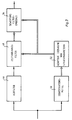
- Figure 3 is a block diagram showing the structure of a filter arrangement which can identify and suppress interference.
- a measured variable here the excitation current of the torque generator 28, is sampled and digitized and supplied to the filter arrangement as an input variable M g (k), where k is a running integer and denotes the cycle.
- This input variable is passed through a pre-filter 46 to a time-variable filter 48 and to identification means 50 for identifying a fault.
- the identification means 50 influence parameter means 52, which adaptively generate control parameters for the time-variable filter.
- the time-variable filter 48 and the parameter means 52 are designed such that when a fault is identified by the identification means 50, the input values that then appear and are filtered by the pre-filter are not taken into account in the filter 48 or are taken into account with reduced weight.
- control parameters of the parameter means 52 are used at the same time for determining the quality of the filter result.
- the control parameters are therefore given to evaluation means 54, by means of which the quality of the filter result is evaluated.
- the filtering is terminated by the evaluation means and the estimated value M g is output when a prescribed quality of the filter result is reached.
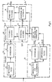
- FIG. 4 shows the application of this principle to the filtering of the output signal, namely the excitation current of the torque generator 28, in a band-suspended meridian gyro according to FIG. 1.
- the computing time-saving implementation form described below is based on a Kalman filter of the lowest possible order.
- the pre-filter 46 contains an average filter 56, which is matched to the dominant natural frequencies of the meridian gyro, and an integration stage 58 connected to it.
- the output of the integration stage 58 is given to a Kalman filter 60.
- the Kalman filter 60 contains a second-order state estimator 62 and covariance means 64 for representing the third-order covariance equation.
- the covariance means 64 provide the time-variable coefficients K1 (k) and K2 (k) for the state estimator.
- the state estimator 62 provides an estimate M ⁇ g (k) for the excitation current of the torque generator 28.
- the Kalman filter is of the type described by the same applicant in the simultaneously filed patent application "Filter for obtaining a time-invariant useful signal from noisy measurements”.
- the input value is also passed on to the identification means 50.
- the identification means 50 contain a variance filter 66 for the “ ⁇ ⁇ oscillation”, that is the natural oscillation of the system about the transverse axis 22.
- the variance filter 66 forms the variance of this oscillation of the measurement signal, that is the sum of the squared Deviation from the mean.
- the filter length is matched so that the variance is a measure of the amplitude square of the oscillation.
- the variance filter thus supplies a value that represents a measure of the ⁇ ⁇ oscillation. According to the model, this vibration is in turn a measure of the faults that occur.
- the output signal of the variance filter A ⁇ (k) is applied to the parameter means with a delay, as represented by block 68.
- the parameter means 52 deliver a weight value r (k) according to a function of the delayed variance A ⁇ (k) determined empirically for a specific meridian gyro. The greater the variance, the smaller the weight r (k).
- the weight value r (k) acts on the covariance means 64 and determines the time-variant filter parameters of the matrix P (k).
- the filter parameters P (k) in turn determine the coefficients K1 (k) and K2 (k) of the state estimator 62.
- the state estimator 62 provides an estimate M ⁇ g (k) for the measured variable, here the excitation current of the torque As long as there are no disturbances, this estimated value for the constant measured variable becomes increasingly better as the measuring time increases.
- the weighting via the weight value r (k) has the effect that input values which occur during such a disturbance are not taken into account in the estimation in the Kalman filter 60 or only with a reduced weight.
- the weight value r (k) and the filter parameters P (k) provide a measure of the quality of the estimate. These values are therefore given to the evaluation means 73. These evaluation means 73 decide whether the required quality of the filtering has been achieved and, via termination means 70, cause the filtering to be terminated and the estimated value M ⁇ g to be output at an output 72
- the basic structure of the filter arrangement is the same as in FIG. 4. Corresponding parts are provided with the same reference numerals as there.
- the variance of the ⁇ ⁇ oscillation from the variance filter 66 is not only passed directly to the parameter means 52 with the delay according to block 68, but also via a differentiating filter 74 as ⁇ A ⁇ (k). This takes into account not only the amplitude of the ⁇ ⁇ oscillation but also the change in this amplitude.
- FIG. 6 the basic structure of the filter arrangement is the same as in FIG. 4. Corresponding parts are given the same reference numerals in FIG. 6 as in FIG. 4.
- ⁇ ⁇ oscillation is used as indicators for the occurrence of a disturbance, but also the other eigen System vibrations and their harmonics. Accordingly, in addition to the variance filter 66 for the ⁇ ⁇ oscillation, a variance filter 76 for the ⁇ oscillation and a variance filter 78 for the ⁇ ⁇ oscillation are provided.
- the variances A ⁇ (k) and A ⁇ ⁇ (k) are given to the parameter means 52 with a delay, represented by blocks 80 and 82, respectively.
Landscapes
- Life Sciences & Earth Sciences (AREA)
- Environmental & Geological Engineering (AREA)
- General Life Sciences & Earth Sciences (AREA)
- Geology (AREA)
- Physics & Mathematics (AREA)
- Engineering & Computer Science (AREA)
- General Physics & Mathematics (AREA)
- Radar, Positioning & Navigation (AREA)
- Remote Sensing (AREA)
- Gyroscopes (AREA)
- Measuring Pulse, Heart Rate, Blood Pressure Or Blood Flow (AREA)
- Percussion Or Vibration Massage (AREA)
- Rehabilitation Tools (AREA)
- Measurement Of Mechanical Vibrations Or Ultrasonic Waves (AREA)
Claims (8)
caractérisée par le fait que
Applications Claiming Priority (2)
| Application Number | Priority Date | Filing Date | Title |
|---|---|---|---|
| DE3836417A DE3836417A1 (de) | 1988-10-26 | 1988-10-26 | Filteranordnung zur erzeugung eines schaetzwertes einer durch stoerungen beeinflussten messgroesse |
| DE3836417 | 1988-10-26 |
Publications (3)
| Publication Number | Publication Date |
|---|---|
| EP0365920A2 EP0365920A2 (fr) | 1990-05-02 |
| EP0365920A3 EP0365920A3 (fr) | 1991-04-17 |
| EP0365920B1 true EP0365920B1 (fr) | 1992-05-06 |
Family
ID=6365932
Family Applications (1)
| Application Number | Title | Priority Date | Filing Date |
|---|---|---|---|
| EP89118871A Expired - Lifetime EP0365920B1 (fr) | 1988-10-26 | 1989-10-11 | Filtre pour créer une valeur estimée d'une mesure influencée par des perturbations |
Country Status (4)
| Country | Link |
|---|---|
| US (1) | US5056052A (fr) |
| EP (1) | EP0365920B1 (fr) |
| DE (2) | DE3836417A1 (fr) |
| NO (1) | NO301192B1 (fr) |
Families Citing this family (9)
| Publication number | Priority date | Publication date | Assignee | Title |
|---|---|---|---|---|
| DE4023349A1 (de) * | 1990-07-23 | 1992-01-30 | Bodenseewerk Geraetetech | Verfahren zur bestimmung der nordrichtung |
| US5546328A (en) * | 1994-06-02 | 1996-08-13 | Ford Motor Company | Method and system for automated alignment of free-form geometries |
| US5638301A (en) * | 1994-06-02 | 1997-06-10 | Ford Motor Company | Method and system for inspecting die sets using free-form inspection techniques |
| NO990038L (no) * | 1998-01-12 | 1999-07-13 | Tokimec Inc | Gyrokompass |
| DE19945688B4 (de) * | 1999-09-23 | 2007-02-15 | Framatome Anp Gmbh | Verfahren und Vorrichtung zur Filterung eines Messsignals |
| US6430525B1 (en) | 2000-06-05 | 2002-08-06 | Masimo Corporation | Variable mode averager |
| US6650124B2 (en) * | 2001-10-05 | 2003-11-18 | Phonak Ag | Method for checking an occurrence of a signal component and device to perform the method |
| DE10340793B4 (de) * | 2003-09-02 | 2006-07-27 | Deutsches Zentrum für Luft- und Raumfahrt e.V. | Verfahren zur rechnerischen Ermittlung systematischer Fehler von prozessierten Zeitreihen-Messdaten |
| DE102011075577B4 (de) * | 2011-05-10 | 2013-01-31 | MULTIPOND Wägetechnik GmbH | Signalverarbeitungsverfahren, Vorrichtung zur Signalverarbeitung und Waage mit Vorrichtung zur Signalverarbeitung |
Family Cites Families (20)
| Publication number | Priority date | Publication date | Assignee | Title |
|---|---|---|---|---|
| DE1941809A1 (de) * | 1969-08-16 | 1971-02-25 | Bodenseewerk Geraetetech | Meridiankreiselgeraet |
| DE2229431A1 (de) * | 1972-06-16 | 1974-01-03 | Bodenseewerk Geraetetech | Nordsuchendes kreiselpendel |
| US3889108A (en) * | 1974-07-25 | 1975-06-10 | Us Navy | Adaptive low pass filter |
| DE2618868A1 (de) * | 1976-04-29 | 1977-11-17 | Bodenseewerk Geraetetech | Geraet zur bestimmung der nordrichtung |
| DE2545026A1 (de) * | 1975-10-08 | 1977-04-14 | Bodenseewerk Geraetetech | Geraet zur bestimmung der nordrichtung |
| DE2922414C2 (de) * | 1979-06-01 | 1985-04-25 | Bodenseewerk Gerätetechnik GmbH, 7770 Überlingen | Kurs-Lage-Referenzgerät |
| US4347730A (en) * | 1979-01-22 | 1982-09-07 | The United States Of America As Represented By The Secretary Of The Army | Method and apparatus for calibrating gyroscopically-stabilized, magnetically-slaved heading reference system |
| US4314343A (en) * | 1980-01-25 | 1982-02-02 | Spectra-Physics, Inc. | Method and apparatus for detecting and integrating chromatographic peaks |
| DE3146374A1 (de) * | 1981-11-23 | 1983-05-26 | Interatom Internationale Atomreaktorbau Gmbh, 5060 Bergisch Gladbach | Verfahren und anordnung zur feststellung und meldung von kuehlungsstoerungen in reaktorkernen |
| DE3119045C2 (de) * | 1981-05-13 | 1985-11-14 | INTERATOM GmbH, 5060 Bergisch Gladbach | Verfahren und Anordnung zur Feststellung und Meldung von Kühlungsstörungen in einem Brennelement eines Reaktorkerns |
| DE3131111C2 (de) * | 1981-08-06 | 1984-05-17 | Bodenseewerk Gerätetechnik GmbH, 7770 Überlingen | Kreiselgerät zur Bestimmung der Nordrichtung |
| DE3131110C1 (de) * | 1981-08-06 | 1983-02-24 | Bodenseewerk Gerätetechnik GmbH, 7770 Überlingen | Kreiselgeraet mit einem bandaufgehaengten Meridiankreisel |
| DE3323648A1 (de) * | 1982-07-03 | 1984-01-05 | Deutsche Forschungs- und Versuchsanstalt für Luft- und Raumfahrt e.V., 5000 Köln | Magnetlager fuer einen rotor |
| DE3229819C2 (de) * | 1982-08-11 | 1985-02-14 | Bodenseewerk Gerätetechnik GmbH, 7770 Überlingen | Integriertes Navigations- und Feuerleitsystem für Kampfpanzer |
| DE3240804A1 (de) * | 1982-11-05 | 1984-05-10 | Teldix Gmbh, 6900 Heidelberg | Verfahren zur ermittlung der nordrichtung |
| GB8425442D0 (en) * | 1984-10-09 | 1984-11-14 | Devon County Council Burns R | Automatic vehicle control method |
| JPH0621814B2 (ja) * | 1986-05-29 | 1994-03-23 | 大和製衡株式会社 | 計重装置の計重信号の濾波方法及び装置 |
| US4775949A (en) * | 1986-06-27 | 1988-10-04 | K-Tron International, Inc. | Weigh feeding system with stochastic control |
| US4791573A (en) * | 1986-09-02 | 1988-12-13 | Sanders Associates, Inc. | State-deviation-estimation circuit employing a phase-locked-loop phase reference |
| DE3701583A1 (de) * | 1987-01-21 | 1988-08-04 | Bodenseewerk Geraetetech | Einrichtung zur bestimmung der zeitlich veraenderlichen lage und von fehlern eines tochternavigationssystems relativ zu einem mutternavigationssystem |
-
1988
- 1988-10-26 DE DE3836417A patent/DE3836417A1/de not_active Withdrawn
-
1989
- 1989-10-11 DE DE8989118871T patent/DE58901337D1/de not_active Expired - Lifetime
- 1989-10-11 EP EP89118871A patent/EP0365920B1/fr not_active Expired - Lifetime
- 1989-10-20 US US07/424,533 patent/US5056052A/en not_active Expired - Lifetime
- 1989-10-25 NO NO894258A patent/NO301192B1/no unknown
Also Published As
| Publication number | Publication date |
|---|---|
| US5056052A (en) | 1991-10-08 |
| NO894258L (no) | 1990-04-27 |
| EP0365920A2 (fr) | 1990-05-02 |
| NO894258D0 (no) | 1989-10-25 |
| DE58901337D1 (de) | 1992-06-11 |
| EP0365920A3 (fr) | 1991-04-17 |
| NO301192B1 (no) | 1997-09-22 |
| DE3836417A1 (de) | 1990-05-03 |
Similar Documents
| Publication | Publication Date | Title |
|---|---|---|
| DE69731423T2 (de) | Radaufhängung-Regelungsgerät mit einem Rechengerät für die relative Geschwindigkeit zwischen gefederter und nicht gefederter Struktur eines Fahrzeuges. | |
| DE102009000743B4 (de) | Vibrationskompensation für Drehratensensoren | |
| DE69929725T2 (de) | Auf das Rollen eines Fahrzeugs ansprechende Vorrichtung | |
| DE102019100423B4 (de) | Gütefaktorkompensation in mems(microelectromechanical system)-gyroskopen | |
| EP0883795B1 (fr) | Dispositif pour determiner la vitesse de rotation | |
| DE3715007A1 (de) | Verfahren und vorrichtung zur kursbestimmung eines landfahrzeugs | |
| DE69710811T2 (de) | Rechengerät für die relative Geschwindigkeit zwischen gefederter und nicht gefederter Struktur eines Fahrzeuges | |
| EP0365920B1 (fr) | Filtre pour créer une valeur estimée d'une mesure influencée par des perturbations | |
| DE10306829A1 (de) | Ermittlung von Fahrzeug-Geschwindigkeiten mit Hilfe von lineare Parameter und Verstärkung variierenden Planungs-Theorien | |
| EP0544108B1 (fr) | Système de commande d'une suspension semi-actif pour véhicules automobiles | |
| EP3045877A1 (fr) | Procédé de fonctionnement d'un appareil de mesure de débit massique coriolis | |
| DE69833771T2 (de) | System zur stabilisierung eines auf einer sich bewegenden plattform montierten objektes | |
| DE102021202132A1 (de) | Verfahren zur Bestimmung einer Detektionssensitivität eines Drehratensensors | |
| WO1988005154A1 (fr) | Procede de navigation pour un vehicule muni d'une boussole electronique | |
| DE112021006803T5 (de) | Verfahren zur Berechnung von Geschwindigkeit und Beschleunigung basierend auf einem Regularisierungsalgorithmus sowie einer Messvorrichtung | |
| DE102008027621A1 (de) | Verfahren zur Ermittlung des Rollwinkels eines einspurigen Kraftfahrzeuges | |
| DE19726006A1 (de) | Drehratensensor und Verfahren zur Auswertung eines Drehratensensors | |
| DE69001356T2 (de) | Stosssensor und einrichtungen, die diesen stosssensor trägt. | |
| DE3131111C2 (de) | Kreiselgerät zur Bestimmung der Nordrichtung | |
| DE102019008491A1 (de) | Capteur inertiel amélioré | |
| EP0468193B1 (fr) | Procédé pour déterminer le nord | |
| DE3323344C2 (fr) | ||
| EP0429472B1 (fr) | Procede perfectionne de reglage automatique sur le nord | |
| DE19532122C1 (de) | Verfahren zur Horizontstabilisierung von Magnetkompassen | |
| DE3131110C1 (de) | Kreiselgeraet mit einem bandaufgehaengten Meridiankreisel |
Legal Events
| Date | Code | Title | Description |
|---|---|---|---|
| PUAI | Public reference made under article 153(3) epc to a published international application that has entered the european phase |
Free format text: ORIGINAL CODE: 0009012 |
|
| AK | Designated contracting states |
Kind code of ref document: A2 Designated state(s): BE CH DE FR GB LI NL SE |
|
| PUAL | Search report despatched |
Free format text: ORIGINAL CODE: 0009013 |
|
| AK | Designated contracting states |
Kind code of ref document: A3 Designated state(s): BE CH DE FR GB LI NL SE |
|
| 17P | Request for examination filed |
Effective date: 19910704 |
|
| 17Q | First examination report despatched |
Effective date: 19911011 |
|
| GRAA | (expected) grant |
Free format text: ORIGINAL CODE: 0009210 |
|
| AK | Designated contracting states |
Kind code of ref document: B1 Designated state(s): BE CH DE FR GB LI NL SE |
|
| REF | Corresponds to: |
Ref document number: 58901337 Country of ref document: DE Date of ref document: 19920611 |
|
| GBT | Gb: translation of ep patent filed (gb section 77(6)(a)/1977) | ||
| ET | Fr: translation filed | ||
| PLBE | No opposition filed within time limit |
Free format text: ORIGINAL CODE: 0009261 |
|
| STAA | Information on the status of an ep patent application or granted ep patent |
Free format text: STATUS: NO OPPOSITION FILED WITHIN TIME LIMIT |
|
| 26N | No opposition filed | ||
| EAL | Se: european patent in force in sweden |
Ref document number: 89118871.6 |
|
| PGFP | Annual fee paid to national office [announced via postgrant information from national office to epo] |
Ref country code: BE Payment date: 19990816 Year of fee payment: 11 |
|
| PGFP | Annual fee paid to national office [announced via postgrant information from national office to epo] |
Ref country code: NL Payment date: 19991029 Year of fee payment: 11 |
|
| PG25 | Lapsed in a contracting state [announced via postgrant information from national office to epo] |
Ref country code: BE Free format text: LAPSE BECAUSE OF NON-PAYMENT OF DUE FEES Effective date: 20001031 |
|
| BERE | Be: lapsed |
Owner name: BODENSEEWERK GERATETECHNIK G.M.B.H. Effective date: 20001031 |
|
| PG25 | Lapsed in a contracting state [announced via postgrant information from national office to epo] |
Ref country code: NL Free format text: LAPSE BECAUSE OF NON-PAYMENT OF DUE FEES Effective date: 20010501 |
|
| NLV4 | Nl: lapsed or anulled due to non-payment of the annual fee |
Effective date: 20010501 |
|
| REG | Reference to a national code |
Ref country code: GB Ref legal event code: IF02 |
|
| PGFP | Annual fee paid to national office [announced via postgrant information from national office to epo] |
Ref country code: FR Payment date: 20080827 Year of fee payment: 20 |
|
| PGFP | Annual fee paid to national office [announced via postgrant information from national office to epo] |
Ref country code: CH Payment date: 20081224 Year of fee payment: 20 |
|
| PGFP | Annual fee paid to national office [announced via postgrant information from national office to epo] |
Ref country code: SE Payment date: 20080827 Year of fee payment: 20 |
|
| PGFP | Annual fee paid to national office [announced via postgrant information from national office to epo] |
Ref country code: DE Payment date: 20081217 Year of fee payment: 20 |
|
| PGFP | Annual fee paid to national office [announced via postgrant information from national office to epo] |
Ref country code: GB Payment date: 20081029 Year of fee payment: 20 |
|
| REG | Reference to a national code |
Ref country code: CH Ref legal event code: PL |
|
| REG | Reference to a national code |
Ref country code: GB Ref legal event code: PE20 Expiry date: 20091010 |
|
| EUG | Se: european patent has lapsed | ||
| PG25 | Lapsed in a contracting state [announced via postgrant information from national office to epo] |
Ref country code: GB Free format text: LAPSE BECAUSE OF EXPIRATION OF PROTECTION Effective date: 20091010 |