EP0366620A1 - Circuit pour la commande d'un moteur à courant continu - Google Patents
Circuit pour la commande d'un moteur à courant continu Download PDFInfo
- Publication number
- EP0366620A1 EP0366620A1 EP89830450A EP89830450A EP0366620A1 EP 0366620 A1 EP0366620 A1 EP 0366620A1 EP 89830450 A EP89830450 A EP 89830450A EP 89830450 A EP89830450 A EP 89830450A EP 0366620 A1 EP0366620 A1 EP 0366620A1
- Authority
- EP
- European Patent Office
- Prior art keywords
- circuit
- motor
- signal
- input
- controlling
- Prior art date
- Legal status (The legal status is an assumption and is not a legal conclusion. Google has not performed a legal analysis and makes no representation as to the accuracy of the status listed.)
- Withdrawn
Links
- 230000000903 blocking effect Effects 0.000 claims 1
- 230000003472 neutralizing effect Effects 0.000 claims 1
- 238000002485 combustion reaction Methods 0.000 description 4
- 238000010586 diagram Methods 0.000 description 3
- 239000003990 capacitor Substances 0.000 description 2
Images

Classifications
-
- H—ELECTRICITY
- H02—GENERATION; CONVERSION OR DISTRIBUTION OF ELECTRIC POWER
- H02P—CONTROL OR REGULATION OF ELECTRIC MOTORS, ELECTRIC GENERATORS OR DYNAMO-ELECTRIC CONVERTERS; CONTROLLING TRANSFORMERS, REACTORS OR CHOKE COILS
- H02P8/00—Arrangements for controlling dynamo-electric motors rotating step by step
- H02P8/22—Control of step size; Intermediate stepping, e.g. microstepping
-
- F—MECHANICAL ENGINEERING; LIGHTING; HEATING; WEAPONS; BLASTING
- F02—COMBUSTION ENGINES; HOT-GAS OR COMBUSTION-PRODUCT ENGINE PLANTS
- F02D—CONTROLLING COMBUSTION ENGINES
- F02D11/00—Arrangements for, or adaptations to, non-automatic engine control initiation means, e.g. operator initiated
- F02D11/06—Arrangements for, or adaptations to, non-automatic engine control initiation means, e.g. operator initiated characterised by non-mechanical control linkages, e.g. fluid control linkages or by control linkages with power drive or assistance
- F02D11/10—Arrangements for, or adaptations to, non-automatic engine control initiation means, e.g. operator initiated characterised by non-mechanical control linkages, e.g. fluid control linkages or by control linkages with power drive or assistance of the electric type
-
- F—MECHANICAL ENGINEERING; LIGHTING; HEATING; WEAPONS; BLASTING
- F02—COMBUSTION ENGINES; HOT-GAS OR COMBUSTION-PRODUCT ENGINE PLANTS
- F02D—CONTROLLING COMBUSTION ENGINES
- F02D11/00—Arrangements for, or adaptations to, non-automatic engine control initiation means, e.g. operator initiated
- F02D11/06—Arrangements for, or adaptations to, non-automatic engine control initiation means, e.g. operator initiated characterised by non-mechanical control linkages, e.g. fluid control linkages or by control linkages with power drive or assistance
- F02D11/10—Arrangements for, or adaptations to, non-automatic engine control initiation means, e.g. operator initiated characterised by non-mechanical control linkages, e.g. fluid control linkages or by control linkages with power drive or assistance of the electric type
- F02D2011/101—Arrangements for, or adaptations to, non-automatic engine control initiation means, e.g. operator initiated characterised by non-mechanical control linkages, e.g. fluid control linkages or by control linkages with power drive or assistance of the electric type characterised by the means for actuating the throttles
- F02D2011/102—Arrangements for, or adaptations to, non-automatic engine control initiation means, e.g. operator initiated characterised by non-mechanical control linkages, e.g. fluid control linkages or by control linkages with power drive or assistance of the electric type characterised by the means for actuating the throttles at least one throttle being moved only by an electric actuator
Definitions
- the present invention relates to a circuit for controlling a direct-current motor, particularly for the control of a throttle valve in an air-intake duct of an internal combustion engine with spark ignition, for controlling the idling speed of the engine.
- Known devices for controlling the idling speed of an internal combustion engine are based on the closed-loop control of the quantity of air supplied to the cylinders.
- the control of the quantity of air supplied to a cylinder is achieved, for example, with the use of a solenoid valve situated in a by-pass duct associated with a throttle valve in an air-intake duct.
- the solenoid valve is operated by means of a square-wave signal with a variable duty cycle generated by an electronic control unit on the basis of certain pieces of information, such as, for example, the rate of rotation of the engine, the engine temperature, the battery voltage, etc., provided by corresponding sensors.
- the adjustment of the quantity of air supplied is achieved by acting on the throttle valve itself, which, in this case, does not have an associated by-pass duct.
- the rest position of the throttle valve at the idling speed is controlled by means of an electric motor, for example, of the direct current type.
- the position of the throttle valve at a particular time is detected, for example, by means of a rotary potentiometer.
- the motor is driven by an electronic control unit on the basis of the signals provided by the potentiometer associated with the throttle valve and by sensors which detect the values assumed by some variables such as, once again, the rate of rotation of the engine, the battery voltage, etc.
- the electronic control units used in the two different types of idling-speed control systems described above have quite different characteristics, given the quite different characteristics of the actuators used.
- control units for the systems with by-pass ducts and associated solenoid valves are arranged to provide the solenoid valve with a control signal with a variable duty cycle, one wonders whether a signal of this type could drive the electric motor for controlling the rest position of the throttle valve in a regulation system which controls the throttle valve.
- This possibility would actually be extremely interesting, since it would enable the use of basically an identical type of electronic control unit (that is, a unit having identical hardware and differing only at the software level) for driving the two types of actuator used in the two different control systems described above.
- the object of the present invention is to produce a circuit for controlling a direct-current motor by means of a square-wave signal whose duty cycle is variable such that the magnitude and the sign of its variations from a predetermined value are indicative of the value of the sign of the desired rate of rotation of the motor.
- a circuit characterised in that it comprises: an input terminal for the control signal with a variable duty cycle, an integrator circuit connected to the input terminal, a comparator circuit for providing an enabling output signal when the amplitude of the signal provided by the integrator circuit is substantially different from the value which corresponds to the predetermined value of the duty cycle of the control signal, and a circuit for controlling the current supply to the motor, which has at least one control input connected to the input terminal and an enabling, input connected to the output of the comparator circuit, and is adapted to supply the motor with a current which flows in one direction or in the opposite direction when the signal provided by the at least one control input is at a high level or at a low level.
- an air-intake duct of an internal combustion engine with spark ignition is indicated A.
- the air coming from a filter passes through this air duct towards the engine, in the direction of the arrows shown.
- the duct A is provided with a throttle valve, indicated B.
- the rest position of this valve, for the idling speed is controlled by a direct-current motor, indicated M, driven by a control circuit C.
- the circuit has an input i to which an electronic control unit ECU supplies a square-wave control signal S whose duty cycle is variable such that the magnitude and the sign of its variations from 50% are indicative of the value and the sign of the desired rate of rotation of the motor M.
- Figure 2 shows an illustrative portion of the signal S which has a period indicated T.
- the first period shown has a duty cycle at 50% and corresponds to the motor M being stationary (rate of rotation equal to ⁇ 0).
- the duty cycle is greater than 50% and the difference ⁇ 1 between this value of the duty cycle and 50% is indicative of the absolute value and the sign of the desired rate of rotation of the motor.
- the signal S once again has a duty cycle of 50%.
- the duty cycle is less than 50% and the variation ⁇ 2 from 50% again indicates the value and the sign of the desired rate of rotation of the motor M.
- the signal S is generated by the unit ECU on the basis of the signals supplied thereto by a plurality of sensors (not illustrated) for detecting the values assumed by some variables, such as the rate of rotation of the engine, the engine temperature, the battery voltage, etc.
- the unit ECU also receives a signal from a position sensor P associated with the throttle valve B. In the embodiment illustrated, this sensor is constituted by a rotary potentiometer.
- the control system shown in Figure 1 is of the closed-loop type.
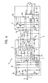
- the control circuit C conveniently has the structure shown in Figure 3 and includes an input buffer circuit D the output of which is connected to the input of an integrator I and to the input e of a driver circuit E.
- the motor M is connected between two output terminals of this circuit.
- the output of the integrator circuit I is connected to the input of a comparator circuit F.
- This circuit is arranged to provide an enabling output signal when the amplitude of the signal provided to it by the integrator circuit I is substantially different from 0, that is, from the value which corresponds to the integral of the signal S in the conditions in which the duty cycle is 50%.
- the output of the comparator circuit F is connected to an enabling input e1 of the driver circuit E.
- the latter circuit is arranged to supply to the motor M with a current which flows in one direction or in the opposite direction when the signal provided at the input e is at a high level or at a low level. This is of course on the condition that the enabling signal provided by the comparator circuit F is present at the input e1.
- V B the direct voltage supplied by a non-stabilised supply source, for example, the battery of the motor vehicle
- V s the voltage delivered by a stabilised direct-voltage supply of, for example, 5V
- the input buffer circuit D includes a pnp-type transistor T1 whose base is connected to the input terminal i through a resistor R1.
- a resistor R2 is arranged between the terminal i and the voltage supply V B .
- a capacitor C1 is connected between the input terminal i and earth.
- the output of the input buffer circuit D is constituted by the collector of T1, and is connected to a passive integrator circuit including a resistor R3 and a capacitor C2.
- the comparator circuit F includes two inverting threshold comparators formed with the use of two operational amplifiers A1 and A2. These comparators compare the signal provided by the integrator circuit I with two different threshold voltages, the higher of which is that associated with A1.
- the output of A2 is connected to the inverting input of a further operational amplifier A3 which acts as an inverter, whilst the output of A1 is connected at M to the output of A3 (a wired-OR-type connection).
- the output of A3 constitutes the output of the comparator circuit F and provides an enabling signal when the output signal provided by the integrator I has an amplitude greater than the threshold associated with A1 or less than the threshold associated with A2.
- A3 The output of A3 is coupled to the enabling input e1 of the driver circuit E by means of a further operational amplifier A4 which acts as an impedance de-coupler.
- the driver circuit E includes a npn-type transistor T2 having its base connected to the collector of T1 and its collector connected to an input pin of an integrated circuit IC.
- This integrated circuit essentially comprises a driving circuit of the full-bridge type (a full-bridge driver) and is conveniently constituted by the circuit produced and marketed by the company SGS under the trade reference L6203.
- the pins of IC have been given the characteristic reference numerals of the commercial circuit mentioned.
- the integrator circuit IC has an input pin (number 7) which is connected directly to the collector of T1.
- the motor M is connected between the pins 1 and 3 of the integrated circuit.
- the pins 2 and 10 are connected to the voltage supply V B and to earth, through a resistor R4 and a resistor R5 respectively.
- An npn-type transistor is indicated T3 and has its base connected to the pin 10 of IC, its emitter connected to earth and its collector connected to the pin 11 of IC.
- the latter pin represents the enabling input of the integrated circuit: when a high-level signal is present at this input, the integrated circuit is enabled and supplies current to the motor M.
- a pnp-type transistor is indicated T4 and has its base connected to the pin 2 of IC, its emitter connected to the voltage supply V B and its collector connected to the base of T3.
- the integrated device IC comprises a full-bridge-type driving circuit whose upper and lower vertices are connected to the pins 2 and 10.
- the resistors R4 and R5 and the transistors T3 and T4 therefore together constitute a protection circuit adapted to neutralise any enabling signal provided by the comparator circuit F when an accidental short-circuit takes place between one terminal of the motor and the voltage source or earth.
- the comparator circuit F applies an enabling signal through A4 to the pin 11 of IC.
- two square-wave signals in phase and in counterphase with S respectively, are applied to the pins 5 and 7 (the control inputs) of IC.
- the signal S is inverted in T1, as well as being amplified, whilst the signal S is inverted twice between the terminal i and the pin 5 (in T1 and T2 respectively).
- the integrated circuit IC is therefore piloted in its "two-phase chopping" operation.
- the values of R1, R2 and C1 are conveniently selected so that, if the connection between the input terminal i and the electronic control unit ECU is broken accidentally, the transistor T1 is blocked and stops the operation of IC. This prevents the throttle valve B from being able to open completely under such circumstances.
Landscapes
- Engineering & Computer Science (AREA)
- Power Engineering (AREA)
- Chemical & Material Sciences (AREA)
- Combustion & Propulsion (AREA)
- Mechanical Engineering (AREA)
- General Engineering & Computer Science (AREA)
- Electrical Control Of Air Or Fuel Supplied To Internal-Combustion Engine (AREA)
- Control Of Direct Current Motors (AREA)
Applications Claiming Priority (2)
| Application Number | Priority Date | Filing Date | Title |
|---|---|---|---|
| IT6795588 | 1988-10-25 | ||
| IT67955/88A IT1223865B (it) | 1988-10-25 | 1988-10-25 | Circuito per il comando di un motore a corrente continua mediante un segnale di comando ad onda quadra a duty cycle variabile particolarmente per il comando di una valvola a farfalla in un condotto di aspirazione dell'aria in un motore a combustione interna |
Publications (1)
| Publication Number | Publication Date |
|---|---|
| EP0366620A1 true EP0366620A1 (fr) | 1990-05-02 |
Family
ID=11306688
Family Applications (1)
| Application Number | Title | Priority Date | Filing Date |
|---|---|---|---|
| EP89830450A Withdrawn EP0366620A1 (fr) | 1988-10-25 | 1989-10-17 | Circuit pour la commande d'un moteur à courant continu |
Country Status (3)
| Country | Link |
|---|---|
| EP (1) | EP0366620A1 (fr) |
| JP (1) | JPH02179296A (fr) |
| IT (1) | IT1223865B (fr) |
Cited By (5)
| Publication number | Priority date | Publication date | Assignee | Title |
|---|---|---|---|---|
| EP0422529A3 (en) * | 1989-10-13 | 1992-11-19 | Weber S.R.L. | System for controlling the electric motor of a vehicle actuating device |
| FR2701790A1 (fr) * | 1993-02-19 | 1994-08-26 | Bosch Gmbh Robert | Procédé et dispositif pour commander un moteur pas à pas. |
| EP0838895A1 (fr) * | 1996-10-25 | 1998-04-29 | Valeo Vision | Commande d'un moteur électrique pas à pas de véhicule automobile, notamment d'un moteur pas à pas pour la correction d'un projecteur |
| EP1030437A3 (fr) * | 1999-02-16 | 2002-04-10 | Lexmark International, Inc. | Méthode et apparail pour commander un servo-moteur utilisant un moteur pas à pas avec un circuit integré de régulation |
| WO2011069869A3 (fr) * | 2009-12-08 | 2012-08-16 | Robert Bosch Gmbh | Moteur électrique avec un modulateur d'amplitude d'impulsion |
Citations (9)
| Publication number | Priority date | Publication date | Assignee | Title |
|---|---|---|---|---|
| FR2385553A1 (fr) * | 1977-03-30 | 1978-10-27 | Vdo Schindling | Dispositif de regulation de la vitesse d'un vehicule |
| FR2549899A1 (fr) * | 1983-07-29 | 1985-02-01 | Bosch Gmbh Robert | Procede et dispositif pour commander la position d'un clapet d'etranglement dans la tubulure d'aspiration d'un moteur a combustion interne |
| US4508078A (en) * | 1982-07-09 | 1985-04-02 | Mazda Motor Corporation | Electrically operated engine throttle valve actuating device |
| US4523565A (en) * | 1984-03-30 | 1985-06-18 | Aisin Seiki Kabushiki Kaisha | Control system and method for a fuel delivery system |
| FR2569231A1 (fr) * | 1984-08-16 | 1986-02-21 | Bosch Gmbh Robert | Dispositif de surveillance pour un clapet d'etranglement commande electroniquement dans un vehicule automobile |
| US4612615A (en) * | 1983-04-11 | 1986-09-16 | Nissan Motor Company, Limited | Throttle control system for automotive vehicle |
| US4641622A (en) * | 1984-06-22 | 1987-02-10 | Nissan Motor Company, Limited | Apparatus for throttle valve control |
| US4765295A (en) * | 1986-06-06 | 1988-08-23 | Honda Giken Kogyo Kabushiki Kaisha | Throttle valve controller for internal combustion engine |
| EP0285868A1 (fr) * | 1987-04-09 | 1988-10-12 | Siemens Aktiengesellschaft | Dispositif de commande de l'air d'admission d'un moteur à combustion |
-
1988
- 1988-10-25 IT IT67955/88A patent/IT1223865B/it active
-
1989
- 1989-10-17 EP EP89830450A patent/EP0366620A1/fr not_active Withdrawn
- 1989-10-24 JP JP1276979A patent/JPH02179296A/ja active Pending
Patent Citations (9)
| Publication number | Priority date | Publication date | Assignee | Title |
|---|---|---|---|---|
| FR2385553A1 (fr) * | 1977-03-30 | 1978-10-27 | Vdo Schindling | Dispositif de regulation de la vitesse d'un vehicule |
| US4508078A (en) * | 1982-07-09 | 1985-04-02 | Mazda Motor Corporation | Electrically operated engine throttle valve actuating device |
| US4612615A (en) * | 1983-04-11 | 1986-09-16 | Nissan Motor Company, Limited | Throttle control system for automotive vehicle |
| FR2549899A1 (fr) * | 1983-07-29 | 1985-02-01 | Bosch Gmbh Robert | Procede et dispositif pour commander la position d'un clapet d'etranglement dans la tubulure d'aspiration d'un moteur a combustion interne |
| US4523565A (en) * | 1984-03-30 | 1985-06-18 | Aisin Seiki Kabushiki Kaisha | Control system and method for a fuel delivery system |
| US4641622A (en) * | 1984-06-22 | 1987-02-10 | Nissan Motor Company, Limited | Apparatus for throttle valve control |
| FR2569231A1 (fr) * | 1984-08-16 | 1986-02-21 | Bosch Gmbh Robert | Dispositif de surveillance pour un clapet d'etranglement commande electroniquement dans un vehicule automobile |
| US4765295A (en) * | 1986-06-06 | 1988-08-23 | Honda Giken Kogyo Kabushiki Kaisha | Throttle valve controller for internal combustion engine |
| EP0285868A1 (fr) * | 1987-04-09 | 1988-10-12 | Siemens Aktiengesellschaft | Dispositif de commande de l'air d'admission d'un moteur à combustion |
Cited By (9)
| Publication number | Priority date | Publication date | Assignee | Title |
|---|---|---|---|---|
| EP0422529A3 (en) * | 1989-10-13 | 1992-11-19 | Weber S.R.L. | System for controlling the electric motor of a vehicle actuating device |
| FR2701790A1 (fr) * | 1993-02-19 | 1994-08-26 | Bosch Gmbh Robert | Procédé et dispositif pour commander un moteur pas à pas. |
| EP0838895A1 (fr) * | 1996-10-25 | 1998-04-29 | Valeo Vision | Commande d'un moteur électrique pas à pas de véhicule automobile, notamment d'un moteur pas à pas pour la correction d'un projecteur |
| FR2755320A1 (fr) * | 1996-10-25 | 1998-04-30 | Valeo Vision | Commande d'un moteur electrique de vehicule automobile, notamment d'un moteur pas a pas pour la correction d'un projecteur |
| EP1030437A3 (fr) * | 1999-02-16 | 2002-04-10 | Lexmark International, Inc. | Méthode et apparail pour commander un servo-moteur utilisant un moteur pas à pas avec un circuit integré de régulation |
| WO2011069869A3 (fr) * | 2009-12-08 | 2012-08-16 | Robert Bosch Gmbh | Moteur électrique avec un modulateur d'amplitude d'impulsion |
| CN102934354A (zh) * | 2009-12-08 | 2013-02-13 | 罗伯特·博世有限公司 | 具有脉冲宽度调制器的电动机 |
| US9018890B2 (en) | 2009-12-08 | 2015-04-28 | Robert Bosch Gmbh | Electric motor having a pulse width modulator |
| CN102934354B (zh) * | 2009-12-08 | 2016-05-18 | 罗伯特·博世有限公司 | 具有脉冲宽度调制器的电动机 |
Also Published As
| Publication number | Publication date |
|---|---|
| JPH02179296A (ja) | 1990-07-12 |
| IT1223865B (it) | 1990-09-29 |
| IT8867955A0 (it) | 1988-10-25 |
Similar Documents
| Publication | Publication Date | Title |
|---|---|---|
| JP3216972B2 (ja) | 内燃機関の点火装置 | |
| JPH06205531A (ja) | 負荷を制御し断線状態を識別するための回路装置 | |
| EP0512920B1 (fr) | Circuit de détection de tension avec transistor connecté en configuration base-commune | |
| US4819597A (en) | Clocked current torque motor control | |
| EP0493750A2 (fr) | Circuit comparateur à hystérésis de précision et impédance d'entrée élevée | |
| EP0366620A1 (fr) | Circuit pour la commande d'un moteur à courant continu | |
| CA1179732A (fr) | Circuit d'attaque pour charges inductives | |
| US6154351A (en) | Apparatus for detecting abnormality in direct current motor driving system | |
| US5299543A (en) | Ignition device for an internal combustion engine | |
| JPS61500925A (ja) | 内燃機関の回転数制御方法及びその装置 | |
| JP3314922B2 (ja) | 負荷駆動システム及びその故障検出方法 | |
| JPS61220013A (ja) | 電気負荷の電流制御装置 | |
| JP3021911B2 (ja) | リニアソレノイドの駆動装置 | |
| JPS6263148A (ja) | 温度補償型インゼクタ制御装置 | |
| JPS6327769A (ja) | 電気回路の動作確認装置 | |
| JP2712363B2 (ja) | 発電型回転数センサの信号入力装置 | |
| JP2662569B2 (ja) | 出力電流検出回路のフェールセーフ回路 | |
| JP4710739B2 (ja) | 負荷断線検出回路 | |
| JP3209519B2 (ja) | 電子回路 | |
| JP3198180B2 (ja) | 負荷異常状態検知回路 | |
| JPH0752372B2 (ja) | ソレノイド駆動回路 | |
| JP3189322B2 (ja) | 電子制御装置 | |
| US20010023678A1 (en) | Compensating voltage controller system | |
| JP2003037930A (ja) | 複数の電源供給回路を備えた制御装置 | |
| KR200154465Y1 (ko) | 자동차의 아이들 스피드 조절 엑추에이터 |
Legal Events
| Date | Code | Title | Description |
|---|---|---|---|
| PUAI | Public reference made under article 153(3) epc to a published international application that has entered the european phase |
Free format text: ORIGINAL CODE: 0009012 |
|
| AK | Designated contracting states |
Kind code of ref document: A1 Designated state(s): AT BE CH DE ES FR GB GR IT LI LU NL SE |
|
| STAA | Information on the status of an ep patent application or granted ep patent |
Free format text: STATUS: THE APPLICATION IS DEEMED TO BE WITHDRAWN |
|
| 18D | Application deemed to be withdrawn |
Effective date: 19901103 |