EP0367210A2 - Détecteur de discontinuité de consommation dans un pare-brise chauffant à alimentation double - Google Patents
Détecteur de discontinuité de consommation dans un pare-brise chauffant à alimentation double Download PDFInfo
- Publication number
- EP0367210A2 EP0367210A2 EP89120159A EP89120159A EP0367210A2 EP 0367210 A2 EP0367210 A2 EP 0367210A2 EP 89120159 A EP89120159 A EP 89120159A EP 89120159 A EP89120159 A EP 89120159A EP 0367210 A2 EP0367210 A2 EP 0367210A2
- Authority
- EP
- European Patent Office
- Prior art keywords
- bus bar
- transparency
- leads
- sensor
- substrate
- Prior art date
- Legal status (The legal status is an assumption and is not a legal conclusion. Google has not performed a legal analysis and makes no representation as to the accuracy of the status listed.)
- Granted
Links
Images


Classifications
-
- H—ELECTRICITY
- H05—ELECTRIC TECHNIQUES NOT OTHERWISE PROVIDED FOR
- H05B—ELECTRIC HEATING; ELECTRIC LIGHT SOURCES NOT OTHERWISE PROVIDED FOR; CIRCUIT ARRANGEMENTS FOR ELECTRIC LIGHT SOURCES, IN GENERAL
- H05B3/00—Ohmic-resistance heating
- H05B3/20—Heating elements having extended surface area substantially in a two-dimensional [2D] plane, e.g. plate-heater
-
- H—ELECTRICITY
- H05—ELECTRIC TECHNIQUES NOT OTHERWISE PROVIDED FOR
- H05B—ELECTRIC HEATING; ELECTRIC LIGHT SOURCES NOT OTHERWISE PROVIDED FOR; CIRCUIT ARRANGEMENTS FOR ELECTRIC LIGHT SOURCES, IN GENERAL
- H05B3/00—Ohmic-resistance heating
- H05B3/84—Heating arrangements specially adapted for transparent or reflecting areas, e.g. for demisting or de-icing windows, mirrors or vehicle windshields
- H05B3/86—Heating arrangements specially adapted for transparent or reflecting areas, e.g. for demisting or de-icing windows, mirrors or vehicle windshields the heating conductors being embedded in the transparent or reflecting material
-
- B—PERFORMING OPERATIONS; TRANSPORTING
- B32—LAYERED PRODUCTS
- B32B—LAYERED PRODUCTS, i.e. PRODUCTS BUILT-UP OF STRATA OF FLAT OR NON-FLAT, e.g. CELLULAR OR HONEYCOMB, FORM
- B32B17/00—Layered products essentially comprising sheet glass, or glass, slag, or like fibres
- B32B17/06—Layered products essentially comprising sheet glass, or glass, slag, or like fibres comprising glass as the main or only constituent of a layer, next to another layer of a specific material
- B32B17/10—Layered products essentially comprising sheet glass, or glass, slag, or like fibres comprising glass as the main or only constituent of a layer, next to another layer of a specific material of synthetic resin
- B32B17/10005—Layered products essentially comprising sheet glass, or glass, slag, or like fibres comprising glass as the main or only constituent of a layer, next to another layer of a specific material of synthetic resin laminated safety glass or glazing
- B32B17/10009—Layered products essentially comprising sheet glass, or glass, slag, or like fibres comprising glass as the main or only constituent of a layer, next to another layer of a specific material of synthetic resin laminated safety glass or glazing characterized by the number, the constitution or treatment of glass sheets
- B32B17/10036—Layered products essentially comprising sheet glass, or glass, slag, or like fibres comprising glass as the main or only constituent of a layer, next to another layer of a specific material of synthetic resin laminated safety glass or glazing characterized by the number, the constitution or treatment of glass sheets comprising two outer glass sheets
-
- B—PERFORMING OPERATIONS; TRANSPORTING
- B32—LAYERED PRODUCTS
- B32B—LAYERED PRODUCTS, i.e. PRODUCTS BUILT-UP OF STRATA OF FLAT OR NON-FLAT, e.g. CELLULAR OR HONEYCOMB, FORM
- B32B17/00—Layered products essentially comprising sheet glass, or glass, slag, or like fibres
- B32B17/06—Layered products essentially comprising sheet glass, or glass, slag, or like fibres comprising glass as the main or only constituent of a layer, next to another layer of a specific material
- B32B17/10—Layered products essentially comprising sheet glass, or glass, slag, or like fibres comprising glass as the main or only constituent of a layer, next to another layer of a specific material of synthetic resin
- B32B17/10005—Layered products essentially comprising sheet glass, or glass, slag, or like fibres comprising glass as the main or only constituent of a layer, next to another layer of a specific material of synthetic resin laminated safety glass or glazing
- B32B17/10165—Functional features of the laminated safety glass or glazing
- B32B17/10174—Coatings of a metallic or dielectric material on a constituent layer of glass or polymer
-
- H—ELECTRICITY
- H05—ELECTRIC TECHNIQUES NOT OTHERWISE PROVIDED FOR
- H05B—ELECTRIC HEATING; ELECTRIC LIGHT SOURCES NOT OTHERWISE PROVIDED FOR; CIRCUIT ARRANGEMENTS FOR ELECTRIC LIGHT SOURCES, IN GENERAL
- H05B2203/00—Aspects relating to Ohmic resistive heating covered by group H05B3/00
- H05B2203/013—Heaters using resistive films or coatings
Definitions
- This invention relates to a power discontinuity sensor in an electrically heatable transparency and in particular to a sensor useable with a heatable windshield having a double feed electrical input configuration to a pair of bus bars that will interrupt electrical power to the bus bars when a break is sensed in the bus bar feeds of the windshield that will cause arcing and additional damage to the heatable windshield.
- a double feed heated transparency and in particular a windshield, includes first and second bus bars each positioned along opposite edges of the windshield to be heated. Power is provided to at least one of the bus bars by dual leads, each attached to opposite ends of the bus bar. In this fashion, if one of the leads fails, the other can still supply power to the bus bar and maintain the windshield's operation.
- U.S. Patent No. 3,892,947 to Strengholt teaches an electrically heated panel with anti-shock conductive strips.
- the electric current conductive strip extends around the periphery of the panel before contacting any portion of an electrically conductive coating on the panel surface. A single break or fracture in the strip will prevent any current from flowing through the coating.
- U.S. Patent No. 4,565,919 to Bitter et al. teaches a crack detector for an electrically conductive windshield.
- the circuit includes a sensor arrangement for monitoring the resistance of the conductive film of the windshield and interrupting power applied to the film when the resistance assumes a value indicative of element cracking.
- the present invention provides a sensor usable with a double feed heatable windshield.
- a double feed heatable windshield provides two power leads to its upper bus bar. As a result, if one of the leads fail, power can still be supplied to the upper bus bar through the remaining lead and the windshield remains functional.
- the present invention allows the windshield to continue operation under such conditions but will detect a condition wherein both leads have failed and localized overheating of the windshield can occur due to arcing. This is achieved by providing a sensor including a sensor filament electrically interconnected to the upper bus bar and double feed configuration downstream from those portions of the bus bar and feeds to be monitored.
- the sensor filament is a wire member embedded in an interlayer ply of the windshield and is electrically interconnected to the upper bus bar by a metal connector extending through the interlayer.
- Current is supplied to the sensor filament from the upper bus bar through the connector to provide two electroconductive paths to power the sensor line.
- the voltage from the sensor filament is monitored and compared to a reference level voltage. When both leads fail so that power to the sensor filament is reduced, the measured voltage drops. This change in voltage is detected and the power to the windshield bus bars is interrupted.
- the present invention teaches a sensor for a double feed heatable windshield that allows the windshield to remain operational when only one lead is defective but will interrupt power to the bus bars when it senses that both leads are defective.
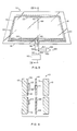
- the transparency 10 includes an outboard glass ply 12, i.e.. the ply furthest from the vehicle interior, a plastic interlayer 14 (shown only in Figure 2) which may be polyvinylbutyral as is commonly used for laminated windshields, and an inboard glass ply 16 shown only in Figure 2).
- a heating arrangement is provided to heat the transparency 10.
- the heating arrangement includes an electroconductive coating 18 preferably positioned on the inside surface 20 of the outboard glass ply 12.
- the coating comprises a silver film between a pair of zinc stannate films with a copper primer between the films, each of which may be applied sequentially by magnetron sputtering.
- the silver acts as an electroconductive layer and the zinc stannate films serve to mask the reflectance of the silver.
- the coating exhibits an approximate resistivity of about 7 to 8 ohms per square when the silver layer has a thickness of about 110 angstroms.
- a bottom bus bar 22 and top bus bar 24 are positioned on the glass ply 12 to be in contact with the coating 18 as shown in Figures 1 and 2.
- Line 26 indicates an edge of the coating 18 spaced from edges of the transparency 10.
- the uncoated marginal areas may be provided by masking these selected portions of the transparency 10 during the coating process. Optionally, the entire glass sheet could be coated and the coating subsequently deleted from those areas. The uncoated marginal areas permit electrical connections to be made to the upper bus bar 24 without contacting the coating 18 or the bottom bus bar 22.
- connection to the upper bus bar 24 of the windshield 10 includes a pair of leads 28 and 30 having conductive strips 32 and 34, respectively, extending in opposite directions along the bottom edge of the windshield 10 from the terminal area 36 and conductive side strips 38 and 40 extending along opposite side portions which connect strips 32 and 34, respectively, to opposite ends of upper bus bar 24.
- leads 28 and 30 having conductive strips 32 and 34, respectively, extending in opposite directions along the bottom edge of the windshield 10 from the terminal area 36 and conductive side strips 38 and 40 extending along opposite side portions which connect strips 32 and 34, respectively, to opposite ends of upper bus bar 24.
- the electrical connections to the bottom bus bar 22 and to the top bus bar 24 via leads 28 and 30 are preferably made along the bottom edge of the windshield 10 at terminal 36 as illustrated in Figure 1 but it should be appreciated that the connections may be made anywhere about the perimeter of the windshield 10.
- the bus bars and conductive strips are preferably made of a silver containing ceramic frit material, as is well known in the art, and may be applied in any convenient manner, e.g. silk screened onto the glass surface 20 of the glass ply 12. After screening, the frit is heated, or "fired", to melt the frit material and fuse it to the glass surface.
- an opaque ceramic enamel border 42 (shown only in Figure 2) may be applied on surface 20 of the glass ply 12 to hide the bus bars 22 and 24 and strips 32, 34, 33, and 40.
- the conductivity of the bus bars and conductive strips is chosen to be considerably greater than that of the coating 18 to provide a fairly even power distribution along the bus bar and prevent the bus bar from overheating.
- voltage sensor 44 includes an electroconductive line 46 which extends from the terminal area 36 at least around a portion of the perimeter of the windshield 10 within the uncoated marginal area.
- Sensor line 46 includes a connecting bridge 48 electrically interconnecting the line 46 with the upper bus bar 24 or a lead to power the line 46 from the upper bus bar 24.
- the line 46 is adjacent to the lead 30 and the connecting bridge 48 is at the juncture between bus bar 24 and strip 40. In operation, it is not necessary for the line 46 carry as much current as the bus bars or leads so that it may be thinner.
- the sensor line 46 and connecting bridge 48 are the same material as the bus bars and leads and are applied during the same silk screening operation.
- electrical lead 50 connects the lower bus bar 22 to one pole of an electrical power source 52.
- Leads 28 and 30 leading to the upper bus bar 24 are wired in common to the opposite pole of power source 52 by means of a jumper wire 54 and lead 56.
- Lead 56 is connected to a voltage comparator circuit 58 by wire 60.
- End 62 of the sensor line 46 at the terminal area 36 is connected to the comparator circuit 58 by wire 64.
- the power discontinuity sensor of the present invention operates to detect a discontinuity, or break, in the strips 32, 34, 38, and 40 by comparing the voltage input from a power source to the upper bus bar 24 through the leads 28 and 30 to the voltage output from the sensor line 46.
- the double lead configuration to the upper bus bar 24 as shown in Figure 1 allows one lead to break and still power the windshield 10 by directing the power through the remaining lead.
- the sensor line arrangement as taught in the present invention recognizes this advantage and will not interrupt power to the windshield 10 if only one of the leads is broken. When both leads are defective so that power no longer reaches the upper bus bar 24, the power builds up and tries to bridge the break in the lead, resulting in localized overheating due to the arcing that can damage the windshield 10.
- the measured voltage from the sensor line 46 which is powered from the bus bar 24 drops. This voltage drop is detected by a comparator circuit which in turn can generate a signal to alert the vehicle operator of the overheating condition and/or interrupt the power to the windshield 10.
- a break in either the upper bus bar 24 or lower bus bar 22 is not as critical as a break in the leads since both sides of the bus bar remain electrically interconnected by the electroconductive coating 18 so that there will be no arcing and associated overheating at the point of the break.
- Power is supplied to the sensor line 46 through two electroconductive paths and referring to the specific configuration of the sensor shown in Figure 1, power is supplied through the lead 28 and upper bus bar 24 and through the lead 30.
- lead 28 breaks so that all the power to the upper bus bar 24 is supplied through lead 30
- the measured voltage of the sensor lead 46 from wire 64 to the comparator 58 will not change appreciably because power will continue to be supplied to the sensor line 46 through lead 30 and the connecting bridge 48.
- the power discontinuity sensor will allow the windshield 10 to continue to function even though one of the leads to the upper bus bar 24 is inoperative.
- the electrical connection of the line 46 through the connecting bridge 48 should be made at a location such that those portions of the bus bar 24 and/or leads 28 and 30 which are to be monitored are between the power connection to the sensor 44, i.e., bridge 48, and the power connection to the leads, i.e., at terminal 36.
- bridge 48 is located downstream of both the power connection to the leads and the portions of the bus bar 24 and leads 28 and 30 which are being monitored for potential defects. More particularly, the connection is made to the bus bar 24 or to the juncture between one of the leads and the bus bar 24.
- connection was made at a location upstream from one of the potential defect areas, for example, at strip 34 of lead 30, a break in both the leads 28 and 30 would go undetected since power will still reach the sensor line 46 through the strip 34 and connecting bridge 48 and the signal to the comparator 58 will not drop so as to indicate that there is a potential for overheating due to arcing.
- the line 46 of the sensor 44 breaks, it is possible that the sensor will interrupt power to the windshield 10 even though it is still operational. For example, if a crack at the perimeter of the windshield 10 extends through the line 46, the comparator 58 will receive a voltage reading indicative of a break in both leads 28 and 30 even though one or both is still functional.
- sensor line 46 breaking due to a peripheral crack in glass ply 12 can be eliminated by removing the line from the surface 20 of the glass ply 12, as taught in U.S. Patent Application Serial No. 290.225 to Carter et al., filed Nov. 4, 1988, which teachings are hereby incorporated by reference.
- sensor line 68 is a wire, preferably a 34 to 36 gauge iron nickel wire, embedded on or within the interlayer 14 in any convenient manner such as that disclosed in U.S. Patent No. 4,078,107 to Bitterace et al, which teachings are hereby incorporated by reference, so that it is electrically insulated from the lower bus bar 22 and the electroconductive coating 18 by interlayer 14.
- Wire 68 is electrically connected to the upper bus bar 24 in any convenient manner.
- connecting bridge 48 is a metal tab 70 (shown only in Figure 4), extending through the interlayer 14 to interconnect the wire 68 with the upper bus bar 24.
- wire 68 in Figure 3 extends across the windshield to the terminal area 36, it is obvious to one skilled in the art that the wire 68 may extend to any other edge of the windshield 10.
- the line sensor 44 can be an electroconductive ceramic frit or a conductive foil (both not shown) secured to surface 71 of inner glass ply 16.
- voltage sensor 144 includes two separate lines 146a and 146b each connected at the juncture between the upper bus bar 24 and leads 28 and 30, respectively, via connecting bridges 148a and 148b, respectively.
- ends 162a and 162b of lines 146a and 146b, respectively, are wired in common by jumper wire 72 connected by lead 74 to the comparator 58.
- Figure 6 shows an alternate embodiment of the comparator circuitry wherein a defect in either lead can be detected and indicated without interrupting the power to the windshield 10.
- End 162a of line 146a is connected by lead 76a to comparator 158a and end 162b of line 146b is connected by lead 76b to comparator 158b.
- Signals from comparators 158a and 158b are received by controller 78 which can interrupt current to the windshield 10 if both comparators indicate a break and a potentially damaging condition for the windshield 10.
- a break in either lead can be indicated to the vehicle operator in any convenient manner, for example a light. With this arrangement, a break in a bus bar or lead can be detected in an operating windshield 10 rather than requiring the windshield to become non-operative before the sensor indicates a power discontinuity or breakage.
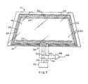
- FIG. 7 illustrates another embodiment of the invention.
- Sensor 244 includes a sensor line 80 extends continuously around the perimeter of the windshield 10, adjacent to the leads 28 and 30 and the upper bus bar 24.
- Connecting bridge 82 electrically interconnects the line 80 to the center of the upper bus bar 24 and the ends of the sensor line 80 at the terminal area 36 are connected to a comparator arrangement similar to that discussed earlier.
- the sensor arrangement shown in Figure 7 is preferred where the windshield requirements necessitate detection of cracks about the perimeter of the windshield which extend through the line 80 even if they do not extend through the bus bars or leads so as to affect the power distribution to the windshield 10 since the operation of the sensor is based on monitoring variations in the voltage of the sensor line 80 rather than the voltage of a bus bar and/or leads.
Landscapes
- Surface Heating Bodies (AREA)
- Control Of Resistance Heating (AREA)
Applications Claiming Priority (2)
| Application Number | Priority Date | Filing Date | Title |
|---|---|---|---|
| US07/267,402 US4902875A (en) | 1988-11-04 | 1988-11-04 | Power discontinuity sensor for a dual feed heatable windshield |
| US267402 | 1988-11-04 |
Publications (3)
| Publication Number | Publication Date |
|---|---|
| EP0367210A2 true EP0367210A2 (fr) | 1990-05-09 |
| EP0367210A3 EP0367210A3 (en) | 1990-08-29 |
| EP0367210B1 EP0367210B1 (fr) | 1994-03-16 |
Family
ID=23018617
Family Applications (1)
| Application Number | Title | Priority Date | Filing Date |
|---|---|---|---|
| EP89120159A Expired - Lifetime EP0367210B1 (fr) | 1988-11-04 | 1989-10-31 | Détecteur de discontinuité de consommation dans un pare-brise chauffant à alimentation double |
Country Status (7)
| Country | Link |
|---|---|
| US (1) | US4902875A (fr) |
| EP (1) | EP0367210B1 (fr) |
| JP (1) | JPH0824064B2 (fr) |
| KR (1) | KR940000799B1 (fr) |
| CA (1) | CA2001562C (fr) |
| DE (1) | DE68913904T2 (fr) |
| ES (1) | ES2052860T3 (fr) |
Cited By (4)
| Publication number | Priority date | Publication date | Assignee | Title |
|---|---|---|---|---|
| WO2013048698A1 (fr) * | 2011-09-28 | 2013-04-04 | Ppg Industries Ohio, Inc. | Circuit électrique et capteur de détection de formation d'arc et transparence ayant le circuit et le capteur |
| US10063047B2 (en) | 2011-09-28 | 2018-08-28 | Ppg Industries Ohio, Inc. | Intelligent window heat control system |
| US11337311B2 (en) | 2018-07-06 | 2022-05-17 | Ppg Industries Ohio, Inc. | Aircraft window with variable power density heater film |
| US11509132B2 (en) | 2011-09-28 | 2022-11-22 | Ppg Industries Ohio, Inc. | Intelligent window heat control system |
Families Citing this family (23)
| Publication number | Priority date | Publication date | Assignee | Title |
|---|---|---|---|---|
| GB9425986D0 (en) | 1994-12-22 | 1995-02-22 | Pilkington Glass Ltd | Electrically heated window |
| US5824993A (en) * | 1995-05-04 | 1998-10-20 | Ford Motor Company | Arrangement for heating an automobile glazing unit |
| US5653903A (en) * | 1995-06-27 | 1997-08-05 | Ppg Industries, Inc. | L-shaped heating element with radiused end for a windshield |
| US5886321A (en) * | 1996-12-19 | 1999-03-23 | Ppg Industries, Inc. | Arrangement for heating the wiper rest area of a vehicle windshield |
| US6492619B1 (en) | 2001-04-11 | 2002-12-10 | Centre Luxembourgeois De Recherches Pour Le Verre Et La Ceramique S.A. (Crvc) | Dual zone bus bar arrangement for heatable vehicle window |
| US6559419B1 (en) | 2001-08-03 | 2003-05-06 | Centre Luxembourgeois De Recherches Pour Le Verre Et La Ceramique S.A. (C.R.V.C.) | Multi-zone arrangement for heatable vehicle window |
| US6734396B2 (en) | 2001-09-07 | 2004-05-11 | Centre Luxembourgeois De Recherches Pour Le Verre Et La Ceramique S.A. (C.R.V.C.) | Heatable vehicle window with different voltages in different heatable zones |
| US8288678B2 (en) * | 2008-12-18 | 2012-10-16 | Ppg Industries Ohio, Inc. | Device for and method of maintaining a constant distance between a cutting edge and a reference surface |
| US8155816B2 (en) * | 2008-12-30 | 2012-04-10 | Ppg Industries Ohio, Inc | Method of and system for maintaining operating performance of a transparency |
| US8383994B2 (en) * | 2008-12-30 | 2013-02-26 | Ppg Industries Ohio, Inc. | Transparency having sensors |
| EA030260B1 (ru) * | 2010-11-18 | 2018-07-31 | Сэн-Гобэн Гласс Франс | Панельный нагреватель с контролем температуры |
| US9491806B2 (en) | 2011-09-30 | 2016-11-08 | Ppg Industries Ohio, Inc. | Heatable transparency |
| EP2817267B1 (fr) | 2012-02-24 | 2019-08-21 | PPG Industries Ohio, Inc. | Verre contenant du lithium à teneur élevée en fer oxydé et son procédé de fabrication |
| US10202302B2 (en) | 2012-02-24 | 2019-02-12 | Ppg Industries Ohio, Inc. | Lithium containing glass with high and low oxidized iron content, and products using same |
| GB201309549D0 (en) | 2013-05-29 | 2013-07-10 | Pilkington Group Ltd | Glazing |
| US9347905B2 (en) | 2013-11-18 | 2016-05-24 | Ppg Industries Ohio, Inc. | Transparency having moisture sensors |
| US9384601B2 (en) | 2014-08-15 | 2016-07-05 | Ppg Industries Ohio, Inc. | Aircraft electronic fingerprint and monitoring performance of an aircraft component using the aircraft's electronic fingerprint |
| US9975646B2 (en) | 2015-07-28 | 2018-05-22 | Ppg Industries Ohio, Inc. | Aerospace transparency having moisture sensors |
| US9983171B2 (en) | 2015-07-28 | 2018-05-29 | Ppg Industries Ohio, Inc. | Aerospace transparency having moisture sensors |
| BR112019010871A2 (pt) | 2016-11-30 | 2019-10-01 | Ppg Ind Ohio Inc | transparência e método para fabricar uma transparência de aeronave tendo um sensor de umidade |
| US10466201B2 (en) | 2018-02-01 | 2019-11-05 | FPG Industries Ohio, Inc. | Complex impedance moisture sensor and sensing method |
| US11229091B2 (en) * | 2018-05-30 | 2022-01-18 | Betterfrost Technologies, Inc. | Continuous resistance and proximity checking for high power deicing and defogging systems |
| US12198484B2 (en) * | 2021-08-18 | 2025-01-14 | Robert Bosch Gmbh | Systems and methods for detecting windshield cracks |
Family Cites Families (19)
| Publication number | Priority date | Publication date | Assignee | Title |
|---|---|---|---|---|
| US3379859A (en) * | 1966-05-26 | 1968-04-23 | Libbey Owens Ford Glass Co | Electrically heated transparent panel and prtective circuit therefor |
| US3526753A (en) * | 1966-12-08 | 1970-09-01 | Ardco Inc | Anti-shock control devices for electrically heated glass |
| GB1386792A (en) * | 1971-04-08 | 1975-03-12 | Rotax Ltd | Electrical heating apparatus for reducing or preventing the formation of ice on aircraft parts |
| US3760157A (en) * | 1972-07-11 | 1973-09-18 | Thermoseal Glass Corp | Electrically heated window with a connector block and a circuit breaker |
| US3892947A (en) * | 1974-02-27 | 1975-07-01 | Donnelly Mirrors Inc | Electrically heated panel with anti-shock conductive strips |
| US3876862A (en) * | 1974-02-27 | 1975-04-08 | Irvin Newman | Electrically-energized glass panel and circuit breaker combination |
| US4057671A (en) * | 1975-06-27 | 1977-11-08 | Ppg Industries, Inc. | Heated laminated window and method of assembling same |
| US4078107A (en) * | 1976-06-28 | 1978-03-07 | Ppg Industries, Inc. | Lightweight window with heating circuit and anti-static circuit and a method for its preparation |
| DE3004457A1 (de) * | 1980-02-07 | 1981-08-13 | Vereinigte Glaswerke Gmbh, 5100 Aachen | Schwenkbares autofenster |
| US4323726A (en) * | 1980-07-24 | 1982-04-06 | Ppg Industries, Inc. | Electrical bus bar assembly |
| US4565919A (en) * | 1984-06-14 | 1986-01-21 | Donnelly Corporation | Crack detector for electrically conductive windshield |
| US4543466A (en) * | 1984-07-02 | 1985-09-24 | Ford Motor Company | Bus bar arrangement for uniformly heating a trapezoidally-shaped electrically heated windshield |
| US4610771A (en) * | 1984-10-29 | 1986-09-09 | Ppg Industries, Inc. | Sputtered films of metal alloy oxides and method of preparation thereof |
| JPS643191Y2 (fr) * | 1984-12-28 | 1989-01-26 | ||
| US4668270A (en) * | 1986-09-11 | 1987-05-26 | Ford Motor Company | Method of making an electrically heated, glass vision unit |
| US4808799A (en) * | 1987-11-07 | 1989-02-28 | Libbey-Owens-Ford Co. | Crack detecting window panel and method of producing same |
| CA1295004C (fr) * | 1988-01-15 | 1992-01-28 | Ppg Industries, Inc. | Detecteur de discontinuite pour transparent chauffe |
| US4829163A (en) * | 1988-02-08 | 1989-05-09 | General Motors Corporation | Crack detector for heated glass panel |
| JPH0299446A (ja) * | 1988-10-04 | 1990-04-11 | Asahi Glass Co Ltd | 電熱ガラスの割れ検出方法 |
-
1988
- 1988-11-04 US US07/267,402 patent/US4902875A/en not_active Expired - Lifetime
-
1989
- 1989-10-26 CA CA002001562A patent/CA2001562C/fr not_active Expired - Fee Related
- 1989-10-31 ES ES89120159T patent/ES2052860T3/es not_active Expired - Lifetime
- 1989-10-31 EP EP89120159A patent/EP0367210B1/fr not_active Expired - Lifetime
- 1989-10-31 DE DE68913904T patent/DE68913904T2/de not_active Expired - Fee Related
- 1989-11-02 JP JP1287310A patent/JPH0824064B2/ja not_active Expired - Fee Related
- 1989-11-04 KR KR1019890015968A patent/KR940000799B1/ko not_active Expired - Fee Related
Cited By (7)
| Publication number | Priority date | Publication date | Assignee | Title |
|---|---|---|---|---|
| US8981265B2 (en) | 2008-12-30 | 2015-03-17 | Ppg Industries Ohio, Inc. | Electric circuit and sensor for detecting arcing and a transparency having the circuit and sensor |
| WO2013048698A1 (fr) * | 2011-09-28 | 2013-04-04 | Ppg Industries Ohio, Inc. | Circuit électrique et capteur de détection de formation d'arc et transparence ayant le circuit et le capteur |
| RU2562966C1 (ru) * | 2011-09-28 | 2015-09-10 | Ппг Индастриз Огайо, Инк. | Электрическая схема и датчик для обнаружения дугообразования и остекление с такими схемой и датчиком |
| US10063047B2 (en) | 2011-09-28 | 2018-08-28 | Ppg Industries Ohio, Inc. | Intelligent window heat control system |
| US10374416B2 (en) | 2011-09-28 | 2019-08-06 | Ppg Industries Ohio, Inc. | Intelligent window heat control system |
| US11509132B2 (en) | 2011-09-28 | 2022-11-22 | Ppg Industries Ohio, Inc. | Intelligent window heat control system |
| US11337311B2 (en) | 2018-07-06 | 2022-05-17 | Ppg Industries Ohio, Inc. | Aircraft window with variable power density heater film |
Also Published As
| Publication number | Publication date |
|---|---|
| JPH02172176A (ja) | 1990-07-03 |
| DE68913904D1 (de) | 1994-04-21 |
| US4902875A (en) | 1990-02-20 |
| KR900008902A (ko) | 1990-06-04 |
| KR940000799B1 (ko) | 1994-01-31 |
| EP0367210A3 (en) | 1990-08-29 |
| CA2001562A1 (fr) | 1990-05-04 |
| DE68913904T2 (de) | 1994-10-20 |
| CA2001562C (fr) | 1994-04-26 |
| EP0367210B1 (fr) | 1994-03-16 |
| ES2052860T3 (es) | 1994-07-16 |
| JPH0824064B2 (ja) | 1996-03-06 |
Similar Documents
| Publication | Publication Date | Title |
|---|---|---|
| US4902875A (en) | Power discontinuity sensor for a dual feed heatable windshield | |
| EP0430119B1 (fr) | Détecteur de champ électrique pour un pare-brise chauffant | |
| US4894513A (en) | Heatable windshield temperature control | |
| US4820902A (en) | Bus bar arrangement for an electrically heated transparency | |
| US5824994A (en) | Electrically heated transparency with multiple parallel and looped bus bar elements | |
| CA1283705C (fr) | Dispositif detecteur de felures d'un panneau vitre | |
| US4939348A (en) | Discontinuity detector in a heated transparency | |
| CA2050999C (fr) | Barre omnibus a cavalier pour pare-brise chauffant | |
| US4847472A (en) | Enhanced reliability discontinuity detector in a heated transparency | |
| EP0341301A1 (fr) | Panneau de fenetre a detection de fissures et procede pour sa fabrication | |
| US12583207B2 (en) | Laminated glass, electrical isolation measurement system having the same, method of manufacturing the same, and use of the same | |
| KR920006268B1 (ko) | 가열 투명체의 단절 검출기 | |
| JPH0270552A (ja) | 故障検出装置を備えた加熱透明体 | |
| JP2707636B2 (ja) | ガラスのヒータ装置 | |
| JP3669055B2 (ja) | 通電加熱ガラス | |
| JPH0299446A (ja) | 電熱ガラスの割れ検出方法 |
Legal Events
| Date | Code | Title | Description |
|---|---|---|---|
| PUAI | Public reference made under article 153(3) epc to a published international application that has entered the european phase |
Free format text: ORIGINAL CODE: 0009012 |
|
| AK | Designated contracting states |
Kind code of ref document: A2 Designated state(s): BE DE ES FR GB IT SE |
|
| PUAL | Search report despatched |
Free format text: ORIGINAL CODE: 0009013 |
|
| AK | Designated contracting states |
Kind code of ref document: A3 Designated state(s): BE DE ES FR GB IT SE |
|
| 17P | Request for examination filed |
Effective date: 19901119 |
|
| 17Q | First examination report despatched |
Effective date: 19930114 |
|
| GRAA | (expected) grant |
Free format text: ORIGINAL CODE: 0009210 |
|
| AK | Designated contracting states |
Kind code of ref document: B1 Designated state(s): BE DE ES FR GB IT SE |
|
| REF | Corresponds to: |
Ref document number: 68913904 Country of ref document: DE Date of ref document: 19940421 |
|
| ET | Fr: translation filed | ||
| ITF | It: translation for a ep patent filed | ||
| REG | Reference to a national code |
Ref country code: ES Ref legal event code: FG2A Ref document number: 2052860 Country of ref document: ES Kind code of ref document: T3 |
|
| PLBE | No opposition filed within time limit |
Free format text: ORIGINAL CODE: 0009261 |
|
| STAA | Information on the status of an ep patent application or granted ep patent |
Free format text: STATUS: NO OPPOSITION FILED WITHIN TIME LIMIT |
|
| EAL | Se: european patent in force in sweden |
Ref document number: 89120159.2 |
|
| 26N | No opposition filed | ||
| REG | Reference to a national code |
Ref country code: FR Ref legal event code: TP |
|
| REG | Reference to a national code |
Ref country code: GB Ref legal event code: 732E |
|
| REG | Reference to a national code |
Ref country code: GB Ref legal event code: IF02 |
|
| PGFP | Annual fee paid to national office [announced via postgrant information from national office to epo] |
Ref country code: FR Payment date: 20021002 Year of fee payment: 14 |
|
| PGFP | Annual fee paid to national office [announced via postgrant information from national office to epo] |
Ref country code: SE Payment date: 20021003 Year of fee payment: 14 |
|
| PGFP | Annual fee paid to national office [announced via postgrant information from national office to epo] |
Ref country code: GB Payment date: 20021023 Year of fee payment: 14 |
|
| PGFP | Annual fee paid to national office [announced via postgrant information from national office to epo] |
Ref country code: BE Payment date: 20021025 Year of fee payment: 14 |
|
| PGFP | Annual fee paid to national office [announced via postgrant information from national office to epo] |
Ref country code: DE Payment date: 20021031 Year of fee payment: 14 |
|
| PGFP | Annual fee paid to national office [announced via postgrant information from national office to epo] |
Ref country code: ES Payment date: 20021106 Year of fee payment: 14 |
|
| PG25 | Lapsed in a contracting state [announced via postgrant information from national office to epo] |
Ref country code: GB Free format text: LAPSE BECAUSE OF NON-PAYMENT OF DUE FEES Effective date: 20031031 Ref country code: BE Free format text: LAPSE BECAUSE OF NON-PAYMENT OF DUE FEES Effective date: 20031031 |
|
| PG25 | Lapsed in a contracting state [announced via postgrant information from national office to epo] |
Ref country code: SE Free format text: LAPSE BECAUSE OF NON-PAYMENT OF DUE FEES Effective date: 20031101 |
|
| PG25 | Lapsed in a contracting state [announced via postgrant information from national office to epo] |
Ref country code: ES Free format text: LAPSE BECAUSE OF NON-PAYMENT OF DUE FEES Effective date: 20031103 |
|
| BERE | Be: lapsed |
Owner name: *PPG INDUSTRIES OHIO INC. UNE SOCIETE DE L'ETAT DE Effective date: 20031031 |
|
| PG25 | Lapsed in a contracting state [announced via postgrant information from national office to epo] |
Ref country code: DE Free format text: LAPSE BECAUSE OF NON-PAYMENT OF DUE FEES Effective date: 20040501 |
|
| GBPC | Gb: european patent ceased through non-payment of renewal fee |
Effective date: 20031031 |
|
| EUG | Se: european patent has lapsed | ||
| PG25 | Lapsed in a contracting state [announced via postgrant information from national office to epo] |
Ref country code: FR Free format text: LAPSE BECAUSE OF NON-PAYMENT OF DUE FEES Effective date: 20040630 |
|
| REG | Reference to a national code |
Ref country code: FR Ref legal event code: ST |
|
| REG | Reference to a national code |
Ref country code: ES Ref legal event code: FD2A Effective date: 20031103 |
|
| PG25 | Lapsed in a contracting state [announced via postgrant information from national office to epo] |
Ref country code: IT Free format text: LAPSE BECAUSE OF NON-PAYMENT OF DUE FEES;WARNING: LAPSES OF ITALIAN PATENTS WITH EFFECTIVE DATE BEFORE 2007 MAY HAVE OCCURRED AT ANY TIME BEFORE 2007. THE CORRECT EFFECTIVE DATE MAY BE DIFFERENT FROM THE ONE RECORDED. Effective date: 20051031 |