EP0367480A2 - Verpacken von kleinen Maschestücken - Google Patents
Verpacken von kleinen Maschestücken Download PDFInfo
- Publication number
- EP0367480A2 EP0367480A2 EP89310958A EP89310958A EP0367480A2 EP 0367480 A2 EP0367480 A2 EP 0367480A2 EP 89310958 A EP89310958 A EP 89310958A EP 89310958 A EP89310958 A EP 89310958A EP 0367480 A2 EP0367480 A2 EP 0367480A2
- Authority
- EP
- European Patent Office
- Prior art keywords
- wrapping material
- mesh
- pieces
- package
- mesh pieces
- Prior art date
- Legal status (The legal status is an assumption and is not a legal conclusion. Google has not performed a legal analysis and makes no representation as to the accuracy of the status listed.)
- Withdrawn
Links
Images


Classifications
-
- B—PERFORMING OPERATIONS; TRANSPORTING
- B65—CONVEYING; PACKING; STORING; HANDLING THIN OR FILAMENTARY MATERIAL
- B65H—HANDLING THIN OR FILAMENTARY MATERIAL, e.g. SHEETS, WEBS, CABLES
- B65H29/00—Delivering or advancing articles from machines; Advancing articles to or into piles
- B65H29/66—Advancing articles in overlapping streams
- B65H29/6609—Advancing articles in overlapping streams forming an overlapping stream
- B65H29/6618—Advancing articles in overlapping streams forming an overlapping stream upon transfer from a first conveyor to a second conveyor advancing at slower speed
-
- B—PERFORMING OPERATIONS; TRANSPORTING
- B65—CONVEYING; PACKING; STORING; HANDLING THIN OR FILAMENTARY MATERIAL
- B65B—MACHINES, APPARATUS OR DEVICES FOR, OR METHODS OF, PACKAGING ARTICLES OR MATERIALS; UNPACKING
- B65B63/00—Auxiliary devices, not otherwise provided for, for operating on articles or materials to be packaged
- B65B63/04—Auxiliary devices, not otherwise provided for, for operating on articles or materials to be packaged for folding or winding articles, e.g. gloves or stockings
-
- B—PERFORMING OPERATIONS; TRANSPORTING
- B65—CONVEYING; PACKING; STORING; HANDLING THIN OR FILAMENTARY MATERIAL
- B65H—HANDLING THIN OR FILAMENTARY MATERIAL, e.g. SHEETS, WEBS, CABLES
- B65H2801/00—Application field
- B65H2801/81—Packaging machines
Definitions
- GB-A-2 120 475 describes a way of strengthening a particulate matrix in which relatively small, light weight, generally flat pieces of flexible, open plastics mesh structure are randomly embedded in the matrix.
- GB-A-2 120 475 can be referred to for details. Such pieces each weigh less than 5g, and have a weight of less than 80 g/m2 or more particularly less than 50 g/m2.
- each individual mesh piece is so small that it is very easily moved by vibration, air flow, static electricity or contact with moving parts, so that there are immense difficulties in providing any ordered arrangement. Furthermore, because the mesh pieces are flat and severed from the same sheet of mesh material, they are very close to each other, and a minimum of movement of any mesh piece will cause interlocking with its neighbour and a chain reaction with other mesh pieces. If this happens, it is nearly impossible to handle the mesh pieces. Because of the way in which the mesh pieces are slit, each piece will have protruding strands around its edges, which easily engage the protruding strands of the next mesh piece, or indeed lock into the meshes of the next mesh piece.
- the present invention provides a method of packing small, light weight mesh pieces having high flexural recovery, which are to be used for strengthening a matrix, comprising depositing the mesh pieces on a length of flexible wrapping material whose width is sufficient to receive a number of the mesh pieces distributed across the width, the mesh pieces being deposited across the width of the wrapping material and also longitudinally of the wrapping material, substantially each mesh piece longitudinally overlapping another mesh piece and being longitudinally overlapped by a further mesh piece, the edge portions of the wrapping material extending beyond those mesh pieces which are nearest the edges; and rolling up the wrapping material to form a package, the underside of the preceding turn of the wrapping material thereby covering the mesh pieces, the edge portions of substantially every turn of the wrapping material being caused to move towards the axis of the package, to provide retention of the mesh pieces along the edges of the package.
- the present invention also provides the package made by the method of the invention, a machine for forming the package, and also a method of mixing small, light weight mesh pieces with a matrix in order to strengthen the matrix, comprising unrolling the package of the invention and using the wrapping material to transport the mesh pieces to a mixer where they are mixed with the matrix.
- the invention can overcome all the problems noted above in a very simple manner.
- the mesh pieces can be laid properly on the wrapping material and firmly secured by the opposed sheet of wrapping material.
- the package particularly if it is rolled up, is very easy to use as the flat overlapping form in which the mesh pieces are maintained mainly eliminates interlocking, and as the package is opened, the mesh pieces readily fall and separate from the wrapping material.
- the package is suitable for continuous feeding to a mixing machine since the mesh pieces can be easily discharged from the wrapping material, eg in the mixing chamber of the machine.
- the mesh pieces can be relatively static-free in the package.
- the edge portions of the wrapping material By moving or bending towards the axis of the package, the edge portions of the wrapping material effectively narrow down or close the gaps at the edges, between adjacent turns of wrapping material, and provide retention of the mesh pieces along the edges of the package, ie stop the mesh pieces falling out of the edges.
- the edges of substantially every turn overlap the edge portions of the preceding turn, as seen looking at the side of the package; the respective edge portions can engage, but as some cockling may occur, the engagement may be intermittent.
- the package can be made to any suitable size or weight, for ease of handling.
- the package can have a density similar to that achieved by conventional baling.
- the wrapping material will be rolled up on a circular core, so that the package is generally circular, but this is not essential - an oblong packet may be formed by rolling onto a rectangular section core, in which case the 'axis' is not so exactly defined but will exist.
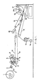
- feed reel 1 of substantial size, being a continuous length of mesh structure as described in GB-A-2 120 475.
- the mesh 2 is fed to a series of rotary side-by-side slitting blades 3 on a rotating shaft, for slitting the mesh 2 into tapes (multiple widths each equal to the pitch of the slitting blades 3).
- the mesh 2 is pulled through the slitting blades 3 by a pair of feed nip rolls 4 which feed the slit tapes into a rotary cross-cutting unit 5.
- the unit 5 has a number of cross-cutting blades 6 mounted on a cylinder 7 which rotates about a transverse axis. Each blade 6 co-acts as a shear with a static transverse blade 8.
- the blades 6 cut the whole width of each tape simultaneously, i.e. the blades 6 have a minimum of transverse angle; if there were not simultaneous cutting, the pieces, after cutting the last strand, would flick sideways and interlock with their neighbours.
- There is a static eliminator 9 which keeps the air surrounding the cross-cutting zone below a static electrical potential of 500 V.
- a take-off conveyor belt 10 which is electrically conductive in order to further reduce by earthing any static electricity retained in the mesh pieces 11.
- the linear velocity of the take-off conveyor belt 10 is greater than the linear velocity of the tapes immediately before being cut, as determined by the rolls 4 - the increase in speed is between 30% and 50%. This spaces the pieces 11 apart in the direction of travel.
- the take-off conveyor belt 10 is positioned so that the leading end of each mesh piece 11 contacts the take-off conveyer belt 10 before the mesh piece 11 is cut off from the tape; this ensures maintenance of the alignment of the mesh pieces 11 after cross-cutting.
- the same conveyor belt 10 acts as a supply conveyor whose downstream end is positioned above the upstream end of a slower conveyor belt 12 which has a high friction rubber surface; the preferred degree of overlap of the pieces 11 on the belt 12 is from 50% to 95%, and the conveyor speeds are regulated accordingly - it is possible to operate with an overlap of less than 50%, but the arrangement is less economic.
- the take-off belt 12 preferably travels at 2% to 50% of the linear feed speed of the rolls 4.
- a roll 13 of stretch wrap film (wrapping material) 13 is positioned so that the film is carried along the belt 12, and there is a tension brake 14 so that the film 13 is under tension (which is within the elastic limit of the film 13) sufficient to stretch the film by 5 to 15%, say 10%; the film 13 acts as the wrapping material and the pieces 11 are deposited on to the film 13.
- the film 13 is sufficiently wide for its edges to extend beyond those pieces 11 which are nearest the edges. The pieces 11 will be projected off the end of the supply conveyor belt 10, but tip slightly forwards as their trailing ends continue to be supported when their leading ends 4 are free.
- the belt 12 is inclined downwards relative to the direction of travel of the pieces 11 at the end of the supply conveyor belt 10, and the trailing edge portion of each piece 11 engages the film 13 before the engagement of the leading edge portion of the piece 11 with the preceding piece 11 - in theory, it would be possible for the leading and trailing ends to engage simultaneously, but this is difficult to achieve in practice. In this way, the falling piece 11 is much less likely to disturb the preceding piece 11.
- the closest vertical distance between the supply belt 10 and the take-off belt 12 should be no more than 120mm to 200mm, and preferably no more than 140 mm, between the belt surfaces. The pieces 11 must fall into the correct position since further movement on the belt 12 is not possible due to the projecting filament ends.
- the supply belt 10 is preferably horizontal and the take-off belt 12 is preferably inclined at 15° to 30° to the horizontal.
- a static eliminator 15 (like the eliminator 9) is provided in the deposition zone, to keep a very low level of static electricity and maintain a flat fall of the pieces 11 from the belt 10 to the belt 12.
- the pieces 11 will be distributed across the width of the film 13 and also longitudinally of the film 13, each piece 11 overlapping the preceding piece and being overlapped by the succeeding piece.
- the amount of overlap depends upon the relative speeds, but can be from 50% up to 98%, for instance.
- the pieces 11 on the film 13 are flattened and compressed by a moving member in the form of a further belt 16 which is smooth surfaced and travels at a velocity 30% - 80% greater than that of the belt 12 and engages the top surfaces of the pieces 11.
- a moving member in the form of a further belt 16 which is smooth surfaced and travels at a velocity 30% - 80% greater than that of the belt 12 and engages the top surfaces of the pieces 11.
- the belts 16, 12 slowly approach each other, then travel parallel to one another.
- the angle between the belts 12, 16 enables a slow compression to take place whilst the difference in speed ensures that all the pieces 11 are lying flat without creasing; once the pieces 11 are lying flat, the belt 16 in general just slips over the tops of the pieces 11.
- the approach angle between the belts 12, 16 is preferably between 10° and 20° with an entry gap between the belts 12, 16 of 120 mm to 200 mm, say 140 mm.
- the winding arrangement 17 comprises an inclined winding rack 18 which carries a winder 19 in such a way that a core 20, for instance of cardboard, is closely adjacent to the end of the belt 16 when winding begins, and moves up the rack 17 as winding proceeds.
- a core 20 for instance of cardboard
- the stretch wrap film 13 is drawn off the braked roll, assisted by the belt 12, which is also driven.
- the tension applied to the film 13 is within its elastic limit.
- the mesh pieces 11 are covered by the preceeding turn and are interleaved and trapped by the spiral of film 13, to form a spiral package or bale 21.
- the film 13 grips the mesh pieces 11 tightly and maintains a dense package.
- the projecting edges 22 (see Figure 3) of the film 13 relax and curl over, ie move or bend towards the axis of the package 21, causing the edge of one turn to overlap and engage the edge portion 22 of the next preceeding turn to provide a closure which prevents the pieces 11 slipping out sideways, ie provides retention of the mesh pieces 11 along the edges of the package 21.
- the turns of the film 13 separate the individual layers of the package 21.
- the film 13 is heat shrinkable and, after rolling up into the package 21, the edges are heated (eg using hot air), causing the projecting edges 22 to shrink and curl over, ie bend towards the axis of the package 21, again providing a closure as described above.
- FIGS 2 and 3 illustrate the completed package or bale 21.
- Figure 4 illustrates a detailed arrangement.
- a feed reel 1 is arranged on a swing-over beam 31 for convenient substitution of the next reel 1.
- a reel run-out sensor 32 is provided as well as a tension system 33 with an edge guide.
- the static eliminators 9, 15 blow ionised air.
- the mesh pieces 11 were generally as in GB-A-2 120 475. Details were as follows: Unit weight of mesh pieces 11 - 40 gms/m2 Width of input mesh (feed reel 1) - 600 mm Pitch of strands - 10 mm x 10 mm Length of pieces 11 - 100 mm Width of pieces 11 - 50 mm Wrapping film 13 - linear low density polyethylene Width of film 13 - 700 mm Unit weight of film - 22 gms/m2 Axial stretch of film - 6% Overlap of pieces - 30% Finished bale weight - 20 Kg (nett) Calculated No. of pieces in bale - 100 000
- FIG. 5 shows a mixing machine or mixer 41 for mixing sand or other soil with the mesh pieces 11 in order to use the mesh pieces 11 as described in GB-A-2 120 475.
- a conventional mixing chamber 42 with a hopper 43 for the sand and counter-rotating mixing blades 44.
- the mixing chamber 41 On one side of the mixing chamber 41, there is an opening provided with a guide roller 45.
- the package 21 In order to feed the mesh pieces 11 into the mixing chamber 42, the package 21 is opened and the leading end of the film 13 is taken around the guide roller 45, as shown and attached to a suitable winding drum (not shown).
- the mesh pieces 11 are then projected off the film 13 into the mixing chamber 42. This manner, the film 13 acts as a carrier or feed conveyor to transport the mesh pieces 13 into the mixer 41.
- Each package will contain a multiplicity of the mesh pieces, i.e. many mesh pieces. Solely to give an impression of the number, the package will contain over say 10000 or 25000 or 50000 pieces.
Landscapes
- Engineering & Computer Science (AREA)
- Mechanical Engineering (AREA)
- Auxiliary Devices For And Details Of Packaging Control (AREA)
- Laminated Bodies (AREA)
- Reinforced Plastic Materials (AREA)
- Packages (AREA)
- Basic Packing Technique (AREA)
Applications Claiming Priority (2)
| Application Number | Priority Date | Filing Date | Title |
|---|---|---|---|
| GB8825773 | 1988-11-03 | ||
| GB888825773A GB8825773D0 (en) | 1988-11-03 | 1988-11-03 | Packing small mesh pieces |
Publications (2)
| Publication Number | Publication Date |
|---|---|
| EP0367480A2 true EP0367480A2 (de) | 1990-05-09 |
| EP0367480A3 EP0367480A3 (de) | 1990-09-05 |
Family
ID=10646271
Family Applications (1)
| Application Number | Title | Priority Date | Filing Date |
|---|---|---|---|
| EP19890310958 Withdrawn EP0367480A3 (de) | 1988-11-03 | 1989-10-24 | Verpacken von kleinen Maschestücken |
Country Status (11)
| Country | Link |
|---|---|
| US (1) | US4993550A (de) |
| EP (1) | EP0367480A3 (de) |
| JP (1) | JPH02242725A (de) |
| AU (1) | AU622728B2 (de) |
| DK (1) | DK531589A (de) |
| FI (1) | FI895217A7 (de) |
| GB (2) | GB8825773D0 (de) |
| MY (1) | MY104259A (de) |
| NO (1) | NO894302L (de) |
| PT (1) | PT92184A (de) |
| ZA (1) | ZA898180B (de) |
Families Citing this family (5)
| Publication number | Priority date | Publication date | Assignee | Title |
|---|---|---|---|---|
| US5197727A (en) * | 1991-02-06 | 1993-03-30 | Fmc Corporation | Interleaving apparatus for rolled up segments |
| US5161793A (en) * | 1991-02-06 | 1992-11-10 | Fmc Corporation | Interleaving apparatus for rolled up segments |
| SE0402848D0 (sv) * | 2004-11-22 | 2004-11-22 | Confib Ab | Method for dosing reinforcing fibres for the manufacturing of fibre concrete and the continuous packing used |
| US20130042577A1 (en) * | 2011-08-15 | 2013-02-21 | Kathleen Magee | Bacon Roll |
| JP6930098B2 (ja) * | 2015-12-25 | 2021-09-01 | 東レ株式会社 | 切込プリプレグの製造方法 |
Family Cites Families (14)
| Publication number | Priority date | Publication date | Assignee | Title |
|---|---|---|---|---|
| US3835992A (en) * | 1972-10-24 | 1974-09-17 | J Adams | Bandage dispensing package |
| NL7313775A (en) * | 1973-10-08 | 1975-04-10 | Stamicarbon | Storing empty bags from bag making machine - by positioning at intervals on carrier foil followed by winding foil |
| US4023706A (en) * | 1975-07-11 | 1977-05-17 | Caterpillar Tractor Co. | Method of preparing fibrous concrete |
| US4279341A (en) * | 1979-10-15 | 1981-07-21 | Illinois Tool Works Inc. | Fastener strip |
| CH642602A5 (de) * | 1980-07-15 | 1984-04-30 | Ferag Ag | Einrichtung zum stapeln von im schuppenstrom anfallenden druckprodukten, wie zeitungen, zeitschriften und dergleichen. |
| CH652379A5 (de) * | 1981-09-18 | 1985-11-15 | Ferag Ag | Wickelkoerper zum aufwickeln von kontinuierlich anfallenden flaechengebilden, insbesondere von druckprodukten in schuppenformation. |
| CH655487B (de) * | 1982-05-05 | 1986-04-30 | ||
| CH656852A5 (de) * | 1982-09-02 | 1986-07-31 | Ferag Ag | Verfahren zum herstellen von versandbereiten paketen von in schuppenformation anfallenden druckprodukten. |
| GB2120475B (en) * | 1982-10-05 | 1983-12-29 | Frank Brian Mercer | Strenhthening a matrix |
| CH659233A5 (de) * | 1983-01-21 | 1987-01-15 | Grapha Holding Ag | Vorrichtung zum aufwickeln eines schuppenstromes aus papierbogen. |
| CH659450A5 (de) * | 1983-02-21 | 1987-01-30 | Ferag Ag | Verfahren und vorrichtung zum speichern von in schuppenformation anfallenden druckprodukten, wie zeitungen, zeitschriften und dgl. |
| DE3314289C2 (de) * | 1983-04-20 | 1987-01-02 | Grünzweig + Hartmann und Glasfaser AG, 6700 Ludwigshafen | Verfahren zum Umwickeln eines sich drehenden Ballens aus Wickelmaterial, insbesondere aus einer kaschierten Mineralfaserbahn, mit einer Schutzbahn zur Verpackung, sowie Vorrichtung zur Durchführung des Verfahrens |
| CH660170A5 (de) * | 1983-05-31 | 1987-03-31 | Ferag Ag | Einrichtung zum zwischenspeichern von druckprodukten. |
| CH657833A5 (de) * | 1983-09-19 | 1986-09-30 | Ferag Ag | Verfahren und vorrichtung zum bilden von mehrlagigen wickeln aus in schuppenformation anfallenden flaechigen, biegsamen erzeugnissen, vorzugsweise druckprodukten. |
-
1988
- 1988-11-03 GB GB888825773A patent/GB8825773D0/en active Pending
-
1989
- 1989-02-01 US US07/304,614 patent/US4993550A/en not_active Expired - Lifetime
- 1989-10-24 EP EP19890310958 patent/EP0367480A3/de not_active Withdrawn
- 1989-10-25 DK DK531589A patent/DK531589A/da not_active Application Discontinuation
- 1989-10-27 ZA ZA898180A patent/ZA898180B/xx unknown
- 1989-10-30 NO NO89894302A patent/NO894302L/no unknown
- 1989-11-01 GB GB8924561A patent/GB2224722B/en not_active Expired - Lifetime
- 1989-11-02 MY MYPI89001532A patent/MY104259A/en unknown
- 1989-11-02 FI FI895217A patent/FI895217A7/fi not_active Application Discontinuation
- 1989-11-02 AU AU44347/89A patent/AU622728B2/en not_active Expired
- 1989-11-02 JP JP1285136A patent/JPH02242725A/ja active Pending
- 1989-11-03 PT PT92184A patent/PT92184A/pt unknown
Also Published As
| Publication number | Publication date |
|---|---|
| AU622728B2 (en) | 1992-04-16 |
| MY104259A (en) | 1994-02-28 |
| GB8924561D0 (en) | 1989-12-20 |
| GB8825773D0 (en) | 1988-12-07 |
| NO894302L (no) | 1990-05-04 |
| AU4434789A (en) | 1990-05-10 |
| PT92184A (pt) | 1990-05-31 |
| GB2224722A (en) | 1990-05-16 |
| DK531589A (da) | 1990-05-04 |
| EP0367480A3 (de) | 1990-09-05 |
| FI895217A7 (fi) | 1990-05-04 |
| ZA898180B (en) | 1990-12-28 |
| FI895217A0 (fi) | 1989-11-02 |
| GB2224722B (en) | 1992-09-23 |
| DK531589D0 (da) | 1989-10-25 |
| JPH02242725A (ja) | 1990-09-27 |
| US4993550A (en) | 1991-02-19 |
| NO894302D0 (no) | 1989-10-30 |
Similar Documents
| Publication | Publication Date | Title |
|---|---|---|
| CA2194422C (en) | Separating a web at a line of weakness | |
| JP3041310B2 (ja) | 紙ナプキンまたは同様な物品を製造するための装置及び方法 | |
| CN105636869B (zh) | 螺旋包装物品的装置和方法 | |
| EP0415377B1 (de) | Maschine und Verfahren zum Anbringen zusätzlicher Umhüllungen an zylindrischen Gegenständen | |
| GB2037714A (en) | Method and apparatus for stacking cut cardboard pieces | |
| GB2112758A (en) | Method of and apparatus for removing flat products especially printed products from a winding core | |
| EP2451713B1 (de) | Verpackungsverfahren und -vorrichtung | |
| JP4871439B2 (ja) | 個別に運ばれる平坦な物体を重なった形態で前進コンベア上に堆積させる装置 | |
| US1545912A (en) | Feeding and stacking method and machine | |
| GB2177686A (en) | Apparatus for zig-zag folding of paper webs | |
| EP0672014A1 (de) | Verfahren und vorrichtung zur bildung von rollen aus streifen kompressiblen materials. | |
| GB2165824A (en) | Shingling and stacking of conveyed sheet material with pre-shingling control of sheet feed | |
| JPH07112753B2 (ja) | 自己接着性付箋紙ブロツクを造るための方法および装置 | |
| EP0114352A2 (de) | Vorrichtung zum Vermeiden von Eselsohren in Faltvorrichtungen | |
| US4993550A (en) | Packing small mesh pieces | |
| US5873450A (en) | Apparatus and method for up-ending workpieces | |
| US5225029A (en) | Apparatus for feeding end securing tapes | |
| CA1301625C (en) | Apparatus for the fabrication of portable tubular-shaped packages formed of printed products | |
| US5308236A (en) | Apparatus for forming noodle bundles | |
| PL108663B1 (en) | Device for assembling and oblong putting on in the bellows form continuous ribbon of material | |
| SI9400125A (en) | Process and device for conveying articles, particulary for automatic packaging plants | |
| CA2005876C (en) | Method and apparatus for the sequential handling of flexible products | |
| US4209956A (en) | Forming overlapped wrappers | |
| US3904186A (en) | Accordion, folding and cutting apparatus | |
| US5244201A (en) | Signature stream interrupt apparatus and method |
Legal Events
| Date | Code | Title | Description |
|---|---|---|---|
| PUAI | Public reference made under article 153(3) epc to a published international application that has entered the european phase |
Free format text: ORIGINAL CODE: 0009012 |
|
| AK | Designated contracting states |
Kind code of ref document: A2 Designated state(s): AT BE CH DE ES FR GR IT LI LU NL SE |
|
| PUAL | Search report despatched |
Free format text: ORIGINAL CODE: 0009013 |
|
| AK | Designated contracting states |
Kind code of ref document: A3 Designated state(s): AT BE CH DE ES FR GR IT LI LU NL SE |
|
| 17P | Request for examination filed |
Effective date: 19910305 |
|
| 17Q | First examination report despatched |
Effective date: 19910906 |
|
| STAA | Information on the status of an ep patent application or granted ep patent |
Free format text: STATUS: THE APPLICATION IS DEEMED TO BE WITHDRAWN |
|
| 18D | Application deemed to be withdrawn |
Effective date: 19920811 |