EP0368573A2 - Méthode et appareillage pour couler des alliages métalliques à bas point de fusion - Google Patents
Méthode et appareillage pour couler des alliages métalliques à bas point de fusion Download PDFInfo
- Publication number
- EP0368573A2 EP0368573A2 EP89311412A EP89311412A EP0368573A2 EP 0368573 A2 EP0368573 A2 EP 0368573A2 EP 89311412 A EP89311412 A EP 89311412A EP 89311412 A EP89311412 A EP 89311412A EP 0368573 A2 EP0368573 A2 EP 0368573A2
- Authority
- EP
- European Patent Office
- Prior art keywords
- cylinder
- valve
- die
- injection
- tank
- Prior art date
- Legal status (The legal status is an assumption and is not a legal conclusion. Google has not performed a legal analysis and makes no representation as to the accuracy of the status listed.)
- Granted
Links
Images


Classifications
-
- B—PERFORMING OPERATIONS; TRANSPORTING
- B22—CASTING; POWDER METALLURGY
- B22D—CASTING OF METALS; CASTING OF OTHER SUBSTANCES BY THE SAME PROCESSES OR DEVICES
- B22D25/00—Special casting characterised by the nature of the product
- B22D25/06—Special casting characterised by the nature of the product by its physical properties
-
- B—PERFORMING OPERATIONS; TRANSPORTING
- B22—CASTING; POWDER METALLURGY
- B22D—CASTING OF METALS; CASTING OF OTHER SUBSTANCES BY THE SAME PROCESSES OR DEVICES
- B22D17/00—Pressure die casting or injection die casting, i.e. casting in which the metal is forced into a mould under high pressure
- B22D17/20—Accessories: Details
- B22D17/30—Accessories for supplying molten metal, e.g. in rations
-
- B—PERFORMING OPERATIONS; TRANSPORTING
- B22—CASTING; POWDER METALLURGY
- B22D—CASTING OF METALS; CASTING OF OTHER SUBSTANCES BY THE SAME PROCESSES OR DEVICES
- B22D17/00—Pressure die casting or injection die casting, i.e. casting in which the metal is forced into a mould under high pressure
- B22D17/02—Hot chamber machines, i.e. with heated press chamber in which metal is melted
- B22D17/04—Plunger machines
Definitions
- the present invention relates to a metal casting process to produce melt-out metal cores for subsequent molding in components made of plastics material. More specifically, the present invention relates to a method and apparatus for casting metal alloys with low melting temperatures to achieve a product with uniform density and a fine grained structure.
- melt-out metal parts of complex shapes are made for use as cores in subsequently molded plastics components.
- cores are made of a low melting temperature alloy and are removed from the plastics components by melting the core and leaving the component.
- metal alloys with low melting temperatures are used for encapsulating components such as turbine blades so they may be held for machining and other finishing steps. After use, the metal from the cores or encapsulations is re-melted and re-used.
- U.S. Patent 4,676,296 is disclosed in U.S. Patent 4,676,296.
- a cylinder is provided in a tank of liquid metal alloy with a passage from the bottom of the cylinder passing out through the tank and into a mold or die.
- a valve is provided in the passage to shut off the flow of molten metal alloy in between injection cycles.
- a piston moves up and down within the cylinder and the cylinder is filled by raising the piston up above a filler aperture in the top of the cylinder to allow liquid metal alloy to flow into the cylinder.
- the piston is moved downwards a predetermined amount so that the liquid metal alloy within the cylinder is pre-pressurized.
- the valve in the passage to the die is opened to permit liquid metal alloy to be injected into the die.
- the present invention provides a valve in the passage or transfer line from the bottom of the cylinder to the mold or die which is located in the metal alloy tank and has a port when the valve is in the closed position that closes the transfer line to the die, but opens up a connection from the cylinder to the liquid metal alloy in the tank.
- This permits molten metal alloy to be drawn into the cyulinder through the port when the valve is in the closed position and the piston is raised. It also enables the piston within the cylinder to be reciprocated several times with the valve closed, thus permitting a change and recirculation of the liquid metal alloy within the cylinder with the liquid metal alloy in the tank.
- the present invention avoids the necessity of pre-pressurizing metal alloy in the cylinder prior to injection into a mold or die. It also permits the injection step to be carried out without having to have a stop limit switch or other control and permits use of a closed die rather than an open die, so that the die provides the volume control and no predetermined volume control is required. Furthermore, by maintaining pressure on the liquid metal alloy in the die during cooling, a casting with uniform density and a fine grain structure is achieved.
- a further improvement in the present invention is that no extra pressure is required on the return stroke when the piston is being raised, as in the case when no port within the tank is provided, because on the return stroke, liquid metal alloy is pulled through the port to enter the cylinder.
- melt-out metal parts is a different operation to die casting wherein metals having higher melting temperatures, generally above 350°C are injected into a die at high pressures.
- die casting shot pressures are generally in the range of 800 to 4000 lbs/in2 (562 to 2809 kPa), and the time for injection is in the order of 30 to 40 milliseconds.
- air can become entrapped and pressures build up in the cylinder and passage to the die.
- These high speed injection processes generally include runners leading into the die, and the unsolidified metal drains back after the casting process.
- melt-out metal parts must be made out of metals that melt below the temperatures of the plastic. Such metals do not lend themselves to high pressure die casting. They are cast at pressures generally in the range of 30 to 50 lbs/in2 (21 to 35 kPa). At higher pressures and faster injection speeds, porous castings can be formed with these metals. In the casting of melt-out metal parts, the metal is not placed under high pressure but allowed to flow into the die, the filling time can vary from about 3 to 30 seconds depending on the size of the metal part. When the die is full of metal, a build up of pressure occurs, generally in the order of 30 to 40 lbs/in2 (21 to 28 kPa) and is maintained for about 1 to 10 seconds, again depending on the size of the metal part. Drain back of molten metal does not need to occur, because the dies are direct cavity injection and do not have runners.
- the castings being cores or other components made of metal alloys with low melting points, have an improved surface finish and a uniform dense fine grained structure over that produced by die casting methods.
- the present invention provides a method of producing a casting or encapsulation from a molten metal alloy or the like having a melting point below about 350°C, including an injection cylinder having an injection piston therein, and means to raise and lower the piston of the cylinder, the injection cylinder having an injection passageway passing through a molten metal alloy tank to inject molten metal alloy from the tank into a die, characterized by the steps of: closing the passageway from the injector cylinder to the die, filling the injection cylinder with molten metal alloy from the tank through a valve port located in the injection passageway at an elevation lower than the injection cylinder, by raising the piston in the cylinder, closing the valve port in the injection passageway and opening the passageway from the injection cylinder to the die, and injecting molten metal alloy into the die by lowering the piston in the cylinder.
- the present invention also provides an apparatus for producing a casting or encapsulation from a molten metal alloy or the like having a melting point below about 350°C, comprising a tank adapted to contain molten metal alloy, a cylinder located in the tank having at its base a connection to an injection passageway leading through the tank to a die located outside the tank, a valve in the passageway located in the tank having a first position where the passageway to the die is open and a second position where the passageway to the die is closed, the connection from the cylinder leading via a valve port opening located in the injection passageway at an elevation lower than the cylinder to the tank, valve operating means to transfer from the first position to the seconds position, a piston within the cylinder, and means to raise the piston in the cylinder with the valve in the second position to fill the cylinder with molten metal alloy and means to lower the piston in the cylinder with the valve in the first position to inject molten metal alloy into the die and control means for the means to raise and lower the piston in the cylinder to control the
- Low melting temperature metal alloys having a melting temperature in the range of about 35°C to 350°C are used for making castings for cores or encapsulation.
- these metal alloys are tin, antimony and lead alloys, and eutectic alloys of bismuth and tin.
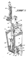
- Figure 1 illustrates a tank 10 filled with molten metal alloy 12 and having an injection cylinder 14 vertically positioned therein, mounted on an injection block 16.
- the injection block 16 is joined to a safety valve body 18 which in turn is attached to the wall 20 of the tank 10.
- a connecting passageway 22 extends from the injection cylinder block 16 where it is joined to the cylinder 14 through the safety valve body 18 and the wall 20 of the tank 10 into a standoff block 24 which is attached to a rotary single lock valve body 26 in turn attached to a manifold 28.
- a nozzle 30 on the manifold 28 extends vertically upwards and joins a die 32 which is a closed die and may be removable from the nozzle 32 for separation and removal of the casting 34 within the die 32.
- the injection cylinder 14 has an injection piston 38 on a shaft 40 which moves up and down within the cylinder 14.
- the piston 38 is powered by a pneumatic cylinder 42 which is double acting and has adjacent to it and joined by a bridge piece 43, a hydraulic cylinder 44 with a hydraulic valve 46 which has a stepper motor 48 to open and close the hydraulic valve 46 and thus affect speed control of the injecting piston 38.
- the air cylinder 42 is double acting, thus powers the piston 38 both upwards and downwards.
- the speed control is set by the stepper motor 48.
- the operation of the safety valve 18 is by a rotary shaft 50 extending up above the level of the molten metal alloy 12 in the tank 10 to a rotary actuator 52.
- the rotary single lock valve 26 is activated by a shaft 54 connected to a rotary actuator 56.
- a micro-processor 58 as illustrated in Figure 1 operates the pneumatic cylinder 42, controls the speed of the piston 30 in the cylinder 14 by the stepper motor 48 and drives the rotary actuators 52 and 56 to control the sequential steps of the casting process.
- a controlled hydraulic cylinder and mechanical means with electronic control may be used.
- FIG 3 illustrates the safety valve 18 and injection cylinder block 16.
- a plug 60 in the valve block 18 is rotated by the actuator shaft 50 to provide a three port two position valve.
- the plug 60 has a T-shaped port 62 which when in the closed position connects to a valve body port 64 which is within the tank 10, thus in the closed position as shown in Figure 4, the cylinder 14 by means of the connecting passage 22 is connected to the valve body port 64 and when the piston 38 is raised in the cylinder 14, liquid metal alloy is pulled into the cylinder through the port 64 and the passageway 22.
- the piston has reached its maximum height, which may be set by a limit switch (not shown), then the safety valve opens to the configuration shown in Figure 5 and the passageway 22 is open from the cylinder 14 to the die 32.
- the filling time for the die 32 is in the range of about 3 to 30 seconds, depending upon the size of the metal part.
- pressure builds up to about 30 to 50 lbs/in2 (21 to 35 kPa) and the pressure is maintained for about 1 to 10 seconds.
- Top ports 70 are provided at the top of the cylinder 14, thus if it is desired to drain the molten metal alloy from the tank 10, it is merely necessary to raise the piston 38 above the top ports 70, and open the valve body port 64 in the safety valve block 18.
- a drain valve (not shown) is provided at the bottom of the tank, and when opened, the liquid level goes down in both the tank and the cylinder at the same time.
- the liquid metal alloy within the cylinder may be changed from time to time by merely reciprocating the piston 38 in the cylinder 14 with the valve port 64 open so that the liquid metal alloy flows in and out as the piston 70 reciprocates.
- the safety valve 18 herein incorporates a rotating plug 60 within a cylindrical aperture of the safety valve body 18.
- the rotating plug 60 provides less leakage and less wear than a reciprocating spool type valve, and performs well at low pressures.
- the lock valve 26 in one embodiment is of the type including a rotating member having a flat surface that rotates on a polished flat surface of a stationary disc.
- the safety valve 18 may be a similar type of valve as the lock valve 26 with an additional port provided so that when the valve is in the closed position, a port in the side wall connects the passageway 22 leading to the cylinder 14 to the liquid metal alloy in the tank 10.
- Liquid metal flow rates delivering metal alloy to a die vary from about 0.1 to 1 Kg/sec.
- the tank 10 maintains the liquid metal alloy therein at the desired temperature, and heaters may be provided in the passageway and lock valve outside the tank as well as in the die to ensure the metal alloys are kept above the melting temperature and flow easily into the dies.
Landscapes
- Engineering & Computer Science (AREA)
- Mechanical Engineering (AREA)
- Injection Moulding Of Plastics Or The Like (AREA)
- Molds, Cores, And Manufacturing Methods Thereof (AREA)
- Casting Support Devices, Ladles, And Melt Control Thereby (AREA)
Applications Claiming Priority (2)
| Application Number | Priority Date | Filing Date | Title |
|---|---|---|---|
| US07/268,492 US4958675A (en) | 1988-11-08 | 1988-11-08 | Method for casting metal alloys with low melting temperatures |
| US268492 | 1988-11-08 |
Publications (3)
| Publication Number | Publication Date |
|---|---|
| EP0368573A2 true EP0368573A2 (fr) | 1990-05-16 |
| EP0368573A3 EP0368573A3 (fr) | 1991-05-29 |
| EP0368573B1 EP0368573B1 (fr) | 1995-01-25 |
Family
ID=23023249
Family Applications (1)
| Application Number | Title | Priority Date | Filing Date |
|---|---|---|---|
| EP89311412A Expired - Lifetime EP0368573B1 (fr) | 1988-11-08 | 1989-11-03 | Méthode et appareillage pour couler des alliages métalliques à bas point de fusion |
Country Status (10)
| Country | Link |
|---|---|
| US (1) | US4958675A (fr) |
| EP (1) | EP0368573B1 (fr) |
| JP (1) | JPH02224858A (fr) |
| KR (1) | KR960015338B1 (fr) |
| AU (1) | AU627241B2 (fr) |
| BR (1) | BR8905895A (fr) |
| DE (1) | DE68920823T2 (fr) |
| ES (1) | ES2068252T3 (fr) |
| MX (1) | MX165310B (fr) |
| ZA (1) | ZA898268B (fr) |
Cited By (2)
| Publication number | Priority date | Publication date | Assignee | Title |
|---|---|---|---|---|
| EP0711616A3 (fr) * | 1994-11-15 | 1997-05-07 | Bachmann Giesserei & Formen | Dispositif pour la coulée des métaux |
| KR101558290B1 (ko) | 2014-04-21 | 2015-10-12 | 해동이엠티(주) | 개량된 로터리 밸브를 갖는 마그네슘 용융물 급탕펌프 장치 |
Families Citing this family (8)
| Publication number | Priority date | Publication date | Assignee | Title |
|---|---|---|---|---|
| DE3233990C2 (de) * | 1982-09-14 | 1986-11-06 | Paul Dipl.-Ing. Dr.-Ing. 5100 Aachen Scherer | Verfahren und Vorrichtungen zur verbesserten Wiedergabe von Phantomschallquellen |
| US5090470A (en) * | 1988-11-08 | 1992-02-25 | Electrovert Ltd. | Apparatus for casting metal alloys with low melting temperatures |
| US5031686A (en) * | 1988-11-08 | 1991-07-16 | Electrovert Ltd. | Method for casting metal alloys with low melting temperatures |
| GB8902120D0 (en) * | 1989-02-01 | 1989-03-22 | Frys Metals Ltd | Casting apparatus & method |
| US5181551A (en) * | 1991-09-25 | 1993-01-26 | Electrovert Ltd. | Double acting cylinder for filling dies with molten metal |
| IT1260341B (it) * | 1992-05-26 | 1996-04-05 | Pressocolatrice a camera calda per leghe leggere | |
| US5435960A (en) * | 1994-01-14 | 1995-07-25 | Freudenberg-Nok General Partnership | Method of making multi-segment plastic components |
| AU4533096A (en) * | 1995-02-27 | 1996-09-18 | Normand Dionne | Fusible alloy for production of melt out core castings and method of casting |
Family Cites Families (20)
| Publication number | Priority date | Publication date | Assignee | Title |
|---|---|---|---|---|
| CH280569A (de) * | 1948-10-01 | 1952-01-31 | Hahn & Kolb | Einrichtung an Giessmaschinen zum Beschicken derselben. |
| US2831214A (en) * | 1956-01-12 | 1958-04-22 | Foster Grant Co Inc | Injection molding apparatus |
| DE1194104B (de) * | 1960-08-08 | 1965-06-03 | Heinr Josef Baggeler | Behaelter zum Abfuellen und Dosieren von fluessigem Metall aus hitzebestaendigem, korrosionsfestem Werkstoff mit am Boden angeordnetem Einlassventil |
| FR1407889A (fr) * | 1964-03-31 | 1965-08-06 | Tokai Rika Co Ltd | Procédé et dispositif de moulage en coquille |
| US3364981A (en) * | 1964-09-29 | 1968-01-23 | Dynacast Int Ltd | Die casting machine |
| GB1073833A (en) * | 1964-09-29 | 1967-06-28 | Perrella Guido | Die casting machine |
| US3300822A (en) * | 1965-05-03 | 1967-01-31 | Gen Motors Corp | Die casting plunger piston ring |
| FR1447606A (fr) * | 1965-09-21 | 1966-07-29 | Buehler Ag Geb | Machine à couler sous pression à chambre froide |
| US3495652A (en) * | 1967-02-06 | 1970-02-17 | Dynacast Int Ltd | Die casting machine with cruciform die guide and pivotally mounted pot and nozzle |
| GB1250476A (fr) * | 1968-01-26 | 1971-10-20 | ||
| US3548921A (en) * | 1968-10-17 | 1970-12-22 | George H Butterfield | Apparatus for molding an arbor to a lens |
| DE2128425A1 (de) * | 1970-08-21 | 1973-01-04 | Friedhelm Dipl Ing Kahn | Giessverfahren mit druckanwendung und einrichtung zur durchfuehrung des verfahrens |
| GB1391785A (en) * | 1971-06-17 | 1975-04-23 | Lewis B R | Apparatus for casting lead and like metals |
| GB1377628A (en) * | 1971-09-24 | 1974-12-18 | Stamp T B | Apparatus for metering or pouring molten metal such as lead |
| CH530249A (de) * | 1971-10-22 | 1972-11-15 | Liechti Fritz Dipl Ing Dr | Verfahren zur Herstellung von Formteilen aus Kunststoffen mit komplizierten Aussparungen und Hohlräumen |
| CA1107030A (fr) * | 1977-12-01 | 1981-08-18 | Dbm Industries Limited | Machine de coulee en forme |
| CA1099476A (fr) * | 1979-03-13 | 1981-04-21 | Remi Frenette | Machine de coulee en moule |
| US4261414A (en) * | 1979-03-21 | 1981-04-14 | Techmire Ltee. | Die casting machine |
| GB8425182D0 (en) * | 1984-10-05 | 1984-11-14 | Frys Metals Ltd | Casting apparatus |
| US4690198A (en) * | 1985-09-27 | 1987-09-01 | Castech Enterprises, Inc. | Injector for injecting molten material into a die |
-
1988
- 1988-11-08 US US07/268,492 patent/US4958675A/en not_active Expired - Fee Related
-
1989
- 1989-10-31 ZA ZA898268A patent/ZA898268B/xx unknown
- 1989-11-03 EP EP89311412A patent/EP0368573B1/fr not_active Expired - Lifetime
- 1989-11-03 DE DE68920823T patent/DE68920823T2/de not_active Expired - Fee Related
- 1989-11-03 ES ES89311412T patent/ES2068252T3/es not_active Expired - Lifetime
- 1989-11-06 AU AU44452/89A patent/AU627241B2/en not_active Ceased
- 1989-11-07 JP JP1289824A patent/JPH02224858A/ja active Pending
- 1989-11-07 KR KR1019890016095A patent/KR960015338B1/ko not_active Expired - Fee Related
- 1989-11-07 MX MX018265A patent/MX165310B/es unknown
- 1989-11-08 BR BR898905895A patent/BR8905895A/pt not_active IP Right Cessation
Cited By (2)
| Publication number | Priority date | Publication date | Assignee | Title |
|---|---|---|---|---|
| EP0711616A3 (fr) * | 1994-11-15 | 1997-05-07 | Bachmann Giesserei & Formen | Dispositif pour la coulée des métaux |
| KR101558290B1 (ko) | 2014-04-21 | 2015-10-12 | 해동이엠티(주) | 개량된 로터리 밸브를 갖는 마그네슘 용융물 급탕펌프 장치 |
Also Published As
| Publication number | Publication date |
|---|---|
| JPH02224858A (ja) | 1990-09-06 |
| EP0368573A3 (fr) | 1991-05-29 |
| MX165310B (es) | 1992-11-04 |
| KR960015338B1 (ko) | 1996-11-09 |
| DE68920823D1 (de) | 1995-03-09 |
| US4958675A (en) | 1990-09-25 |
| AU627241B2 (en) | 1992-08-20 |
| ES2068252T3 (es) | 1995-04-16 |
| AU4445289A (en) | 1990-05-17 |
| DE68920823T2 (de) | 1995-05-24 |
| ZA898268B (en) | 1990-08-29 |
| BR8905895A (pt) | 1990-06-12 |
| KR900007518A (ko) | 1990-06-01 |
| EP0368573B1 (fr) | 1995-01-25 |
Similar Documents
| Publication | Publication Date | Title |
|---|---|---|
| EP0606259B1 (fr) | Cylindre a double effet servant a remplir des moules d'un metal en fusion | |
| KR101070972B1 (ko) | 다이 캐스팅에 의해 금속 부품들을 제조하기 위한 방법 및장치 | |
| EP0527747B1 (fr) | Mecanisme de vannes utilise dans le coulage d'alliages metalliques a basses temperatures de fusion | |
| US2181157A (en) | Method and apparatus for pressure casting | |
| US5758711A (en) | Molding apparatus for minimizing shrinkage and voids | |
| EP0368573B1 (fr) | Méthode et appareillage pour couler des alliages métalliques à bas point de fusion | |
| US4991641A (en) | Method of and apparatus for metal casting | |
| EP0177257B1 (fr) | Machine de coulée | |
| US4562875A (en) | Die-casting method and apparatus | |
| US5887642A (en) | Pressurized squeeze casting apparatus and method and low pressure furnace for use therewith | |
| KR20040100916A (ko) | 3개의 챔버들을 이용한 수직 주입 기계 | |
| US4085791A (en) | Method of pore-free die casting | |
| US5090470A (en) | Apparatus for casting metal alloys with low melting temperatures | |
| US5031686A (en) | Method for casting metal alloys with low melting temperatures | |
| CA1324873C (fr) | Methode et appareil servant au coulage d'alliages metalliques a basses temperatures | |
| US2454961A (en) | Method and apparatus for casting aluminum | |
| US5088546A (en) | Vacuum-assisted counter gravity casting apparatus with valve to prevent flow of melt from mold | |
| KR102932065B1 (ko) | 알루미늄 후육 부품의 고품위 주조장치 및 방법 | |
| JP3518227B2 (ja) | 低融点合金鋳造方法 | |
| JP4509343B2 (ja) | 半溶融金属素材の鍛造方法および鍛造装置 | |
| CN1876279A (zh) | 一种铸造车用空调压缩机缸体、缸盖坯件的工艺方法 | |
| WO2002090020A1 (fr) | Procede et dispositif destines a former rapidement et economiquement au moins un produit moule sous pression sans gaspillage de matiere de moulage | |
| US3476172A (en) | Methods of die casting materials of relatively high melting temperatures | |
| JPS6076265A (ja) | 金型の排気並びに押湯装置 | |
| HK1123770A (en) | Diecasting method and device |
Legal Events
| Date | Code | Title | Description |
|---|---|---|---|
| PUAI | Public reference made under article 153(3) epc to a published international application that has entered the european phase |
Free format text: ORIGINAL CODE: 0009012 |
|
| AK | Designated contracting states |
Kind code of ref document: A2 Designated state(s): BE DE ES FR GB IT NL SE |
|
| PUAL | Search report despatched |
Free format text: ORIGINAL CODE: 0009013 |
|
| AK | Designated contracting states |
Kind code of ref document: A3 Designated state(s): BE DE ES FR GB IT NL SE |
|
| 17P | Request for examination filed |
Effective date: 19910716 |
|
| 17Q | First examination report despatched |
Effective date: 19930712 |
|
| RAP1 | Party data changed (applicant data changed or rights of an application transferred) |
Owner name: ELECTROVERT LTD. |
|
| GRAA | (expected) grant |
Free format text: ORIGINAL CODE: 0009210 |
|
| AK | Designated contracting states |
Kind code of ref document: B1 Designated state(s): BE DE ES FR GB IT NL SE |
|
| ITF | It: translation for a ep patent filed | ||
| EAL | Se: european patent in force in sweden |
Ref document number: 89311412.4 |
|
| REF | Corresponds to: |
Ref document number: 68920823 Country of ref document: DE Date of ref document: 19950309 |
|
| ET | Fr: translation filed | ||
| REG | Reference to a national code |
Ref country code: ES Ref legal event code: FG2A Ref document number: 2068252 Country of ref document: ES Kind code of ref document: T3 |
|
| PLBE | No opposition filed within time limit |
Free format text: ORIGINAL CODE: 0009261 |
|
| STAA | Information on the status of an ep patent application or granted ep patent |
Free format text: STATUS: NO OPPOSITION FILED WITHIN TIME LIMIT |
|
| 26N | No opposition filed | ||
| PGFP | Annual fee paid to national office [announced via postgrant information from national office to epo] |
Ref country code: GB Payment date: 19961101 Year of fee payment: 8 |
|
| PGFP | Annual fee paid to national office [announced via postgrant information from national office to epo] |
Ref country code: FR Payment date: 19961120 Year of fee payment: 8 |
|
| PGFP | Annual fee paid to national office [announced via postgrant information from national office to epo] |
Ref country code: SE Payment date: 19961121 Year of fee payment: 8 |
|
| PGFP | Annual fee paid to national office [announced via postgrant information from national office to epo] |
Ref country code: DE Payment date: 19961122 Year of fee payment: 8 Ref country code: BE Payment date: 19961122 Year of fee payment: 8 |
|
| PGFP | Annual fee paid to national office [announced via postgrant information from national office to epo] |
Ref country code: NL Payment date: 19961129 Year of fee payment: 8 Ref country code: ES Payment date: 19961129 Year of fee payment: 8 |
|
| PG25 | Lapsed in a contracting state [announced via postgrant information from national office to epo] |
Ref country code: GB Free format text: LAPSE BECAUSE OF NON-PAYMENT OF DUE FEES Effective date: 19971103 |
|
| PG25 | Lapsed in a contracting state [announced via postgrant information from national office to epo] |
Ref country code: SE Free format text: LAPSE BECAUSE OF NON-PAYMENT OF DUE FEES Effective date: 19971104 Ref country code: ES Free format text: LAPSE BECAUSE OF NON-PAYMENT OF DUE FEES Effective date: 19971104 |
|
| PG25 | Lapsed in a contracting state [announced via postgrant information from national office to epo] |
Ref country code: FR Free format text: THE PATENT HAS BEEN ANNULLED BY A DECISION OF A NATIONAL AUTHORITY Effective date: 19971130 Ref country code: BE Free format text: LAPSE BECAUSE OF NON-PAYMENT OF DUE FEES Effective date: 19971130 |
|
| BERE | Be: lapsed |
Owner name: ELECTROVERT LTD Effective date: 19971130 |
|
| PG25 | Lapsed in a contracting state [announced via postgrant information from national office to epo] |
Ref country code: NL Free format text: LAPSE BECAUSE OF NON-PAYMENT OF DUE FEES Effective date: 19980601 |
|
| GBPC | Gb: european patent ceased through non-payment of renewal fee |
Effective date: 19971103 |
|
| PG25 | Lapsed in a contracting state [announced via postgrant information from national office to epo] |
Ref country code: DE Free format text: LAPSE BECAUSE OF NON-PAYMENT OF DUE FEES Effective date: 19980801 |
|
| EUG | Se: european patent has lapsed |
Ref document number: 89311412.4 |
|
| NLV4 | Nl: lapsed or anulled due to non-payment of the annual fee |
Effective date: 19980601 |
|
| REG | Reference to a national code |
Ref country code: FR Ref legal event code: ST |
|
| REG | Reference to a national code |
Ref country code: ES Ref legal event code: FD2A Effective date: 19981212 |
|
| PG25 | Lapsed in a contracting state [announced via postgrant information from national office to epo] |
Ref country code: IT Free format text: LAPSE BECAUSE OF NON-PAYMENT OF DUE FEES;WARNING: LAPSES OF ITALIAN PATENTS WITH EFFECTIVE DATE BEFORE 2007 MAY HAVE OCCURRED AT ANY TIME BEFORE 2007. THE CORRECT EFFECTIVE DATE MAY BE DIFFERENT FROM THE ONE RECORDED. Effective date: 20051103 |