EP0370524A2 - Dispositif d'isolation des vibrations et son procédé de fabrication - Google Patents
Dispositif d'isolation des vibrations et son procédé de fabrication Download PDFInfo
- Publication number
- EP0370524A2 EP0370524A2 EP89121750A EP89121750A EP0370524A2 EP 0370524 A2 EP0370524 A2 EP 0370524A2 EP 89121750 A EP89121750 A EP 89121750A EP 89121750 A EP89121750 A EP 89121750A EP 0370524 A2 EP0370524 A2 EP 0370524A2
- Authority
- EP
- European Patent Office
- Prior art keywords
- intermediate cylindrical
- cylindrical case
- flexible membrane
- liquid
- main body
- Prior art date
- Legal status (The legal status is an assumption and is not a legal conclusion. Google has not performed a legal analysis and makes no representation as to the accuracy of the status listed.)
- Granted
Links
Images


Classifications
-
- B—PERFORMING OPERATIONS; TRANSPORTING
- B29—WORKING OF PLASTICS; WORKING OF SUBSTANCES IN A PLASTIC STATE IN GENERAL
- B29C—SHAPING OR JOINING OF PLASTICS; SHAPING OF MATERIAL IN A PLASTIC STATE, NOT OTHERWISE PROVIDED FOR; AFTER-TREATMENT OF THE SHAPED PRODUCTS, e.g. REPAIRING
- B29C45/00—Injection moulding, i.e. forcing the required volume of moulding material through a nozzle into a closed mould; Apparatus therefor
- B29C45/14—Injection moulding, i.e. forcing the required volume of moulding material through a nozzle into a closed mould; Apparatus therefor incorporating preformed parts or layers, e.g. injection moulding around inserts or for coating articles
-
- B—PERFORMING OPERATIONS; TRANSPORTING
- B29—WORKING OF PLASTICS; WORKING OF SUBSTANCES IN A PLASTIC STATE IN GENERAL
- B29C—SHAPING OR JOINING OF PLASTICS; SHAPING OF MATERIAL IN A PLASTIC STATE, NOT OTHERWISE PROVIDED FOR; AFTER-TREATMENT OF THE SHAPED PRODUCTS, e.g. REPAIRING
- B29C33/00—Moulds or cores; Details thereof or accessories therefor
- B29C33/12—Moulds or cores; Details thereof or accessories therefor with incorporated means for positioning inserts, e.g. labels
- B29C33/123—Moulds or cores; Details thereof or accessories therefor with incorporated means for positioning inserts, e.g. labels for centering the inserts
-
- B—PERFORMING OPERATIONS; TRANSPORTING
- B29—WORKING OF PLASTICS; WORKING OF SUBSTANCES IN A PLASTIC STATE IN GENERAL
- B29C—SHAPING OR JOINING OF PLASTICS; SHAPING OF MATERIAL IN A PLASTIC STATE, NOT OTHERWISE PROVIDED FOR; AFTER-TREATMENT OF THE SHAPED PRODUCTS, e.g. REPAIRING
- B29C70/00—Shaping composites, i.e. plastics material comprising reinforcements, fillers or preformed parts, e.g. inserts
- B29C70/68—Shaping composites, i.e. plastics material comprising reinforcements, fillers or preformed parts, e.g. inserts by incorporating or moulding on preformed parts, e.g. inserts or layers, e.g. foam blocks
- B29C70/84—Shaping composites, i.e. plastics material comprising reinforcements, fillers or preformed parts, e.g. inserts by incorporating or moulding on preformed parts, e.g. inserts or layers, e.g. foam blocks by moulding material on preformed parts to be joined
-
- F—MECHANICAL ENGINEERING; LIGHTING; HEATING; WEAPONS; BLASTING
- F16—ENGINEERING ELEMENTS AND UNITS; GENERAL MEASURES FOR PRODUCING AND MAINTAINING EFFECTIVE FUNCTIONING OF MACHINES OR INSTALLATIONS; THERMAL INSULATION IN GENERAL
- F16F—SPRINGS; SHOCK-ABSORBERS; MEANS FOR DAMPING VIBRATION
- F16F13/00—Units comprising springs of the non-fluid type as well as vibration-dampers, shock-absorbers, or fluid springs
- F16F13/04—Units comprising springs of the non-fluid type as well as vibration-dampers, shock-absorbers, or fluid springs comprising both a plastics spring and a damper, e.g. a friction damper
- F16F13/06—Units comprising springs of the non-fluid type as well as vibration-dampers, shock-absorbers, or fluid springs comprising both a plastics spring and a damper, e.g. a friction damper the damper being a fluid damper, e.g. the plastics spring not forming a part of the wall of the fluid chamber of the damper
- F16F13/08—Units comprising springs of the non-fluid type as well as vibration-dampers, shock-absorbers, or fluid springs comprising both a plastics spring and a damper, e.g. a friction damper the damper being a fluid damper, e.g. the plastics spring not forming a part of the wall of the fluid chamber of the damper the plastics spring forming at least a part of the wall of the fluid chamber of the damper
- F16F13/14—Units of the bushing type, i.e. loaded predominantly radially
-
- B—PERFORMING OPERATIONS; TRANSPORTING
- B29—WORKING OF PLASTICS; WORKING OF SUBSTANCES IN A PLASTIC STATE IN GENERAL
- B29K—INDEXING SCHEME ASSOCIATED WITH SUBCLASSES B29B, B29C OR B29D, RELATING TO MOULDING MATERIALS OR TO MATERIALS FOR MOULDS, REINFORCEMENTS, FILLERS OR PREFORMED PARTS, e.g. INSERTS
- B29K2021/00—Use of unspecified rubbers as moulding material
Definitions
- the present invention relates to a vibration isolating device having a liquid room being a space defined mainly by a vibration absorbing main body and a flexible membrane and in which a liquid is charged, the liquid room being divided by an orifice into sub liquid rooms, and a method for manufacturing the vibration isolating device.
- a vibration isolating device which comprises an annular vibration absorbing main body made of an elastic material containing a natural rubber having a low loss factor and which is dished at the top thereof and also has attached on the outer circumference thereof a clamping ring to which a top plate is fixed by caulking, a receptacle having an arch-like sectional shape being attached on the inner bottom circumference of the vibration absorbing main body, and a flexible membrane disposed along the bottom surface of the receptacle and having the circumferential edge sandwiched between the receptacle and a bottom plate.
- the above-mentioned conventional vibration isolating device is not of a so-called bush type structure having an inner and outer cylinders are used, and its structure is not suitable for improving the damping effect by lengthening the orifice.
- the present invention has an object to provide a bush-type vibration isolating device having a flexible membrane which is not degraded even at a high temperature and a long orifice, and a method for manufacturing the rubber cushion.
- a vibration isolating device comprising, according the present invention, a liquid room being a hollow space defined mainly by a vibration absorbing main body made of an elastic material containing a natural rubber having a low loss factor and a flexible membrane made of an elastic material containg a rubber having a heat and ozone resistant property and in which a liquid is charged, the liquid room being divided through an orifice into sub liquid rooms, the vibration absorbing main body in which an inner cylinder is inserted and the flexible membrane being attached to intermediate cylindrical case by vulcanizing the orifice being formed between the outer circumference of the intermediate cylindrical case and an outer cylinder, and a metallic cylinder in which the orifice is formed and the intermediate cylindrical case being press-fitted in the outer cylinder.
- vibration isolating device generation of ozone crack can be prevented even with the flexible membrane of a reduced thickness and the dynamic spring constant can be limited to a low value for the vibration absorbing main body to provide the anti-vibration performance peculiar to the vibration isolating device.
- the vibration isolating device according to the present invnetion is of a bush type structure, so that the orifice can be lengthened and the orifice length can be freely designed to make the most of the damping effect of the liquid.
- the method for manufacturing the vibration isolating device comprises the steps of clamping an injection mold with an inner cylinder and a split-structure intermediate cylindrical case set inside the mold, and injecting an elastic material containing a rubber having a heat-and ozone-resistant property into the cavity formed for one of the split parts of the intermediate cylindrical case while injecting an elastic material containing a natural rubber into the cavity for the other split part of the intermediate cylindrical case and inner cylinder, thereby forming a vibration absorbing main body and flexible membrane in the respective cavities.
- another method comprises the steps of setting a semifinished product not yet vulcanized but generally shaped into the form of the flexible membrane in the cavity for the flexible membrane and injecting an elastic material such as natural rubber into the other cavity, thereby forming a vibration absorbing main body and flexible membrane in the respective cavities. Since the vibration absorbing main body and flexible membrane are attached to the split-structure intermediate cylindrical case by vulcanizing, vibration isolating devices can be produced rapidly and massively by the injection molding by these methods.
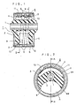
- Fig. 1 shows a first embodiment of vibration isolating device according to the present invention, in which an inner cylinder 1 is inserted in a vibration absorbing main body 2 attached to a split-structure intermediate cylindrical case 3 by vulcanizing. Also a flexible membrane 4 is attached to the split-structure intermediate cylindrical case 3 by vulcanizing.
- the vibration absorbing main body 2 is made of an elastic material containing a natural rubber having a low loss factor
- the flexible membrane 4 is made of an elastic material containing a rubber having a heat- and ozone-resistant property.
- a material containing natural rubber as base and butadiene as additive is suitable for the vibration absorbing main body 2.
- a rubber highly resistant against ozone and low in permeability such as butyric rubber, EPT rubber or a natural rubber to which EPT rubber is added, is suitable.
- the metallic cylinder 6 consists of two blocks. They are fitted around the intermediate cylindrical case.
- the metallic cylinder 6 and intermediate cylindrical case 3 are inserted inside an outer cylinder 11, and they are close fitted to each other by drawing the outer cylinder 11 to a smaller diameter.
- a rubber seal 13 made of the same kind of rubber as the flexible membrane 4 is provided on the outer circumference of the intermediate cylindrical case 3 instead of the O-ring 12 used in the first embodiment.
- the rest of the vibration isolating device structure is the same as in Figs. 1 and 2, and so the vibration isolating device according to the second embodiment will not be described any further.
- Fig. 5 shows the method for manufacturing the vibration isolating device according to the present invention.
- a material for the vibration absorbing main body 2 and a material for the flexible membrane 4 are injected into cavities 17 and 18, respectively, in an injection mold 16 from nozzles 14 and 15, respectively, of an injection molder (not shown).
- the injection mold 16 is fastened with the inner cylinder 1 and the split-structure cylindrical case 3 set in the injection mold 16, and the different materials are injected into the cavities 17 and 18, respectively, from the nozzles 14 and 15, respectively.
- the vibration absorbing main body 2 and flexible membrane 4 thus molded by the so-called double injection molding are taken out from their respective cavities 17 and 18.
- the metallic cylinder 6 in which the orifice is formed is assembled to the outer circumference of the intermediate cylindrical case 6, and the intermediate cylindrical case 3 and the metallic cylinder 6 are inserted into the outer cylinder 11.
- the intermediate cylindrical case 3 and metallic cylinder 6 are close-fitted to each other.
- a hollow space defined mainly by the vibration absorbing main body 2 and flexible membrane 4 is charged with the liquid. This space is called "liquid room”.
- the liquid room is divided through the orifice 5 into sub liquid rooms 7 and 8.
- the injection mold 16 consists of an upper block 16A, middle blocks 16B to 16E and a low block 16D.
- the inner cylinder 1 and split-structure cylindrical case 3 are set inside the injection mold 16, while a semifinished product 4′ not yet vulcanized but generally shaped in the form of the flexible membrane is set in the cavity for the flexible membrane of a rubber having a heat-and ozone-resistant property at the other part of the split-structure intermediate cylindrical case 3. Therefore, injection is made into the cavity 17 alone from the nozzle 14 to mold the vibration absorbing main body 2.
- the flexible membrane 4 is molded taking a longer time than the vibration absorbing main body 2. So a semifinished product 4′ is set beforehand and molded for a time until the vibration absorbing main body 2 in molded in the cavity 17.
- a semifinished product 4′ which can be molded and vulcanized in about 5 to 6 minutes is to be previously set since the time for molding of a rubber containing mainly a natural rubber for the vibration absorbing main body in the cavity 17 may be 5 to 6 minutes because the time for molding and vulcanizing of the butyric rubber is 15 to 20 minutes.
- a semifinished product 4′ which can be molded and vulcanized in about 5 to 6 minutes is to be previously set since the time for molding of a rubber containing mainly a natural rubber for the vibration absorbing main body in the cavity 17 may be 5 to 6 minutes because the time for molding and vulcanizing of the butyric rubber is 15 to 20 minutes.
- the flexible membrane in the vibration isolating device according to the present invention and which is in contact with air has an improved durability and since a long orifice can be provided in the metallic cylinder inside the intermediate cylindrical case, the damping function can be improved.
- the vibration absorbing main body and flexible membrane can be molded by a double injection molding using an injection mold, or only the vibration absorbing main body can be injected molded with a semifinished product of the flexible membrane set beforehand, whereby a vibration isolating device can be manufactured easily and rapidly.
Landscapes
- Engineering & Computer Science (AREA)
- Mechanical Engineering (AREA)
- General Engineering & Computer Science (AREA)
- Manufacturing & Machinery (AREA)
- Chemical & Material Sciences (AREA)
- Composite Materials (AREA)
- Combined Devices Of Dampers And Springs (AREA)
- Injection Moulding Of Plastics Or The Like (AREA)
- Laminated Bodies (AREA)
- Moulds For Moulding Plastics Or The Like (AREA)
Applications Claiming Priority (2)
| Application Number | Priority Date | Filing Date | Title |
|---|---|---|---|
| JP297894/88 | 1988-11-25 | ||
| JP63297894A JP2949684B2 (ja) | 1988-11-25 | 1988-11-25 | 防振ゴムの製造方法 |
Publications (3)
| Publication Number | Publication Date |
|---|---|
| EP0370524A2 true EP0370524A2 (fr) | 1990-05-30 |
| EP0370524A3 EP0370524A3 (en) | 1990-07-18 |
| EP0370524B1 EP0370524B1 (fr) | 1993-11-10 |
Family
ID=17852487
Family Applications (1)
| Application Number | Title | Priority Date | Filing Date |
|---|---|---|---|
| EP89121750A Expired - Lifetime EP0370524B1 (fr) | 1988-11-25 | 1989-11-24 | Dispositif d'isolation des vibrations et son procédé de fabrication |
Country Status (3)
| Country | Link |
|---|---|
| EP (1) | EP0370524B1 (fr) |
| JP (1) | JP2949684B2 (fr) |
| DE (1) | DE68910644T2 (fr) |
Cited By (7)
| Publication number | Priority date | Publication date | Assignee | Title |
|---|---|---|---|---|
| EP0641954A1 (fr) * | 1993-09-02 | 1995-03-08 | Tokai Rubber Industries, Ltd. | Isolateur de vibrations en caoutchouc avec support et son procédé de fabrication |
| EP0686786A1 (fr) * | 1994-06-06 | 1995-12-13 | Mazda Motor Corporation | Appareil d'amortissement des vibrations et méthode de fabrication |
| EP0703383A1 (fr) * | 1994-08-25 | 1996-03-27 | Mazda Motor Corporation | Support de moteur contenant du liquide et son procédé de fabrication |
| EP0726408A1 (fr) * | 1995-02-13 | 1996-08-14 | Hutchinson | Manchon antivibratoire hydraulique et son procédé de fabrication |
| EP0697544A3 (fr) * | 1994-08-10 | 1997-06-04 | Gencorp Inc | Manchon à amortissement hydraulique |
| FR2865511A1 (fr) * | 2004-01-27 | 2005-07-29 | Cf Gomma Spa | Procede de fabrication d'un dispositif d'articulation a masse elastique constituee de blocs de nature differente. |
| CN114542638A (zh) * | 2022-03-11 | 2022-05-27 | 华北水利水电大学 | 一种磁性液体阻尼减振器 |
Families Citing this family (2)
| Publication number | Priority date | Publication date | Assignee | Title |
|---|---|---|---|---|
| JPH0366947A (ja) * | 1989-08-02 | 1991-03-22 | Toyoda Gosei Co Ltd | 液封入防振装置 |
| CN206555347U (zh) * | 2016-12-02 | 2017-10-13 | 株洲时代新材料科技股份有限公司 | 一种轨道交通用液压衬套 |
Family Cites Families (5)
| Publication number | Priority date | Publication date | Assignee | Title |
|---|---|---|---|---|
| FR2363024A1 (fr) * | 1976-08-25 | 1978-03-24 | Paulstra Sa | Perfectionnements apportes aux articulations elastiques et aux procedes pour les etablir |
| JPH055305Y2 (fr) * | 1985-09-18 | 1993-02-12 | ||
| JP2793588B2 (ja) * | 1988-01-12 | 1998-09-03 | 日産自動車株式会社 | 液体入りブツシユ形防振装置 |
| DE3808630A1 (de) * | 1988-03-15 | 1989-10-05 | Metzeler Gmbh | Elastische und hydraulisch daempfende buchse |
| JPH01168036U (fr) * | 1988-05-18 | 1989-11-27 |
-
1988
- 1988-11-25 JP JP63297894A patent/JP2949684B2/ja not_active Expired - Fee Related
-
1989
- 1989-11-24 EP EP89121750A patent/EP0370524B1/fr not_active Expired - Lifetime
- 1989-11-24 DE DE89121750T patent/DE68910644T2/de not_active Expired - Fee Related
Cited By (13)
| Publication number | Priority date | Publication date | Assignee | Title |
|---|---|---|---|---|
| EP0641954A1 (fr) * | 1993-09-02 | 1995-03-08 | Tokai Rubber Industries, Ltd. | Isolateur de vibrations en caoutchouc avec support et son procédé de fabrication |
| US5769380A (en) * | 1993-09-02 | 1998-06-23 | Tokai Rubber Industries, Ltd. | Rubber vibration isolator with bracket and method of manufacturing the same |
| EP0686786A1 (fr) * | 1994-06-06 | 1995-12-13 | Mazda Motor Corporation | Appareil d'amortissement des vibrations et méthode de fabrication |
| US5735510A (en) * | 1994-06-06 | 1998-04-07 | Mazda Motor Corporation | Vibration damper apparatus |
| EP0697544A3 (fr) * | 1994-08-10 | 1997-06-04 | Gencorp Inc | Manchon à amortissement hydraulique |
| US5823515A (en) * | 1994-08-25 | 1998-10-20 | Mazda Motor Corporation | Fluid contained engine mounting device and method of manufacturing the same |
| EP0703383A1 (fr) * | 1994-08-25 | 1996-03-27 | Mazda Motor Corporation | Support de moteur contenant du liquide et son procédé de fabrication |
| US5613668A (en) * | 1995-02-13 | 1997-03-25 | Hutchinson | Hydraulic antivibration sleeve, and its method of manufacture |
| FR2730537A1 (fr) * | 1995-02-13 | 1996-08-14 | Hutchinson | Manchon antivibratoire hydraulique et son procede de fabrication |
| EP0726408A1 (fr) * | 1995-02-13 | 1996-08-14 | Hutchinson | Manchon antivibratoire hydraulique et son procédé de fabrication |
| FR2865511A1 (fr) * | 2004-01-27 | 2005-07-29 | Cf Gomma Spa | Procede de fabrication d'un dispositif d'articulation a masse elastique constituee de blocs de nature differente. |
| EP1568912A1 (fr) * | 2004-01-27 | 2005-08-31 | CF Gomma Spa | Procédé de fabrication d'un dispositif d'articulation à masse élastique constituée de blocs de nature differente |
| CN114542638A (zh) * | 2022-03-11 | 2022-05-27 | 华北水利水电大学 | 一种磁性液体阻尼减振器 |
Also Published As
| Publication number | Publication date |
|---|---|
| JPH02146331A (ja) | 1990-06-05 |
| JP2949684B2 (ja) | 1999-09-20 |
| EP0370524A3 (en) | 1990-07-18 |
| DE68910644T2 (de) | 1994-05-11 |
| DE68910644D1 (de) | 1993-12-16 |
| EP0370524B1 (fr) | 1993-11-10 |
Similar Documents
| Publication | Publication Date | Title |
|---|---|---|
| EP0370524A2 (fr) | Dispositif d'isolation des vibrations et son procédé de fabrication | |
| US5776568A (en) | Hollow body with an internal supporting frame | |
| EP0115174B1 (fr) | Support hydraulique en élastomère | |
| US3287485A (en) | Method of providing a fluid tight seal between two rigid components | |
| JPS6052337B2 (ja) | 水力式架台 | |
| US5170999A (en) | Vibration isolating device, and method for manufacturing same | |
| US6749186B2 (en) | Hydraulic bushing with springs in parallel | |
| US4611795A (en) | Hydraulic-elastomeric mount | |
| JPH01176827A (ja) | 内外筒型流体封入式パワーユニットマウント | |
| JPS60136638A (ja) | 流体圧式エラストマ−・マウント | |
| JP3682813B2 (ja) | 液体封入式マウント及びその組立方法 | |
| JPH02146328A (ja) | 筒状防振ブッシュの製造方法 | |
| KR102575440B1 (ko) | 자동차용 엔진 마운트 및 이의 제조 방법 | |
| US5185916A (en) | Method for producing cylindrical bushing with hydraulic damping | |
| US20030137087A1 (en) | Hydraulic bushing with springs in series | |
| JPS58170610A (ja) | サスペンシヨンブツシユ構造 | |
| US20190301556A1 (en) | Method for manufacturing vibration isolation apparatus | |
| JPH05126185A (ja) | 防振ゴム及びその製造方法 | |
| JPH02256934A (ja) | 筒形防振ゴム | |
| JPS643341A (en) | Fluid-sealed type vibro-isolating bush | |
| JPH0960686A (ja) | 円筒型液体封入式防振装置 | |
| JP2002276712A (ja) | ブッシュ | |
| JP2608538B2 (ja) | 防振装置の製造方法 | |
| JPS60175836A (ja) | 防振ゴムマウント | |
| JPH06257644A (ja) | ダンパの製造方法 |
Legal Events
| Date | Code | Title | Description |
|---|---|---|---|
| PUAI | Public reference made under article 153(3) epc to a published international application that has entered the european phase |
Free format text: ORIGINAL CODE: 0009012 |
|
| PUAL | Search report despatched |
Free format text: ORIGINAL CODE: 0009013 |
|
| AK | Designated contracting states |
Kind code of ref document: A2 Designated state(s): DE FR GB |
|
| AK | Designated contracting states |
Kind code of ref document: A3 Designated state(s): DE FR GB |
|
| 17P | Request for examination filed |
Effective date: 19901211 |
|
| 17Q | First examination report despatched |
Effective date: 19910625 |
|
| GRAA | (expected) grant |
Free format text: ORIGINAL CODE: 0009210 |
|
| AK | Designated contracting states |
Kind code of ref document: B1 Designated state(s): DE FR GB |
|
| REF | Corresponds to: |
Ref document number: 68910644 Country of ref document: DE Date of ref document: 19931216 |
|
| ET | Fr: translation filed | ||
| PLBE | No opposition filed within time limit |
Free format text: ORIGINAL CODE: 0009261 |
|
| STAA | Information on the status of an ep patent application or granted ep patent |
Free format text: STATUS: NO OPPOSITION FILED WITHIN TIME LIMIT |
|
| 26N | No opposition filed | ||
| PGFP | Annual fee paid to national office [announced via postgrant information from national office to epo] |
Ref country code: FR Payment date: 19971112 Year of fee payment: 9 |
|
| PGFP | Annual fee paid to national office [announced via postgrant information from national office to epo] |
Ref country code: GB Payment date: 19971117 Year of fee payment: 9 |
|
| PGFP | Annual fee paid to national office [announced via postgrant information from national office to epo] |
Ref country code: DE Payment date: 19971201 Year of fee payment: 9 |
|
| PG25 | Lapsed in a contracting state [announced via postgrant information from national office to epo] |
Ref country code: GB Free format text: LAPSE BECAUSE OF NON-PAYMENT OF DUE FEES Effective date: 19981124 |
|
| GBPC | Gb: european patent ceased through non-payment of renewal fee |
Effective date: 19981124 |
|
| PG25 | Lapsed in a contracting state [announced via postgrant information from national office to epo] |
Ref country code: FR Free format text: LAPSE BECAUSE OF NON-PAYMENT OF DUE FEES Effective date: 19990730 |
|
| REG | Reference to a national code |
Ref country code: FR Ref legal event code: ST |
|
| PG25 | Lapsed in a contracting state [announced via postgrant information from national office to epo] |
Ref country code: DE Free format text: LAPSE BECAUSE OF NON-PAYMENT OF DUE FEES Effective date: 19990901 |