EP0371134A1 - Dispositif de transfert de bobines chargees et non chargees pour metiers a filer - Google Patents
Dispositif de transfert de bobines chargees et non chargees pour metiers a filer Download PDFInfo
- Publication number
- EP0371134A1 EP0371134A1 EP89901740A EP89901740A EP0371134A1 EP 0371134 A1 EP0371134 A1 EP 0371134A1 EP 89901740 A EP89901740 A EP 89901740A EP 89901740 A EP89901740 A EP 89901740A EP 0371134 A1 EP0371134 A1 EP 0371134A1
- Authority
- EP
- European Patent Office
- Prior art keywords
- peg
- tray
- bar
- trays
- driving bar
- Prior art date
- Legal status (The legal status is an assumption and is not a legal conclusion. Google has not performed a legal analysis and makes no representation as to the accuracy of the status listed.)
- Withdrawn
Links
Images


Classifications
-
- D—TEXTILES; PAPER
- D01—NATURAL OR MAN-MADE THREADS OR FIBRES; SPINNING
- D01H—SPINNING OR TWISTING
- D01H9/00—Arrangements for replacing or removing bobbins, cores, receptacles, or completed packages at paying-out or take-up stations ; Combination of spinning-winding machine
- D01H9/18—Arrangements for replacing or removing bobbins, cores, receptacles, or completed packages at paying-out or take-up stations ; Combination of spinning-winding machine for supplying bobbins, cores, receptacles, or completed packages to, or transporting from, paying-out or take-up stations ; Arrangements to prevent unwinding of roving from roving bobbins
- D01H9/187—Arrangements for replacing or removing bobbins, cores, receptacles, or completed packages at paying-out or take-up stations ; Combination of spinning-winding machine for supplying bobbins, cores, receptacles, or completed packages to, or transporting from, paying-out or take-up stations ; Arrangements to prevent unwinding of roving from roving bobbins on individual supports, e.g. pallets
Definitions
- the present invention relates to an apparatus for transporting full and empty bobbins in a textile machine such as a ring spinning frame or a ring twisting frame.
- a bobbin transportation To carry out a bobbin exchange operation for textile machine such as a ring spinning frame by an auto-doffer, preferably a bobbin transportation.
- apparatus is provided for arranging empty bobbins in front of the spinning frame and removing full bobbins doffed from spindles from an operative zone of the spinning frame.
- a conveyor system is used as the above type of transporting apparatus, in which a plurality of pegs for mounting bobbins are secured on an endless belt at a pitch equal to that of a spindle of the spinning frame or half thereof.
- Such a conveyor system has a drawback in that the conveyor belt is stretched and elongated by long term use, and thus the predetermined pitch between adjacent pegs is adversely widened to cause problems in the operation of the auto-doffer.
- Japanese Unexamined Patent Publication No. 57-161133 discloses a bobbin transporting apparatus, in which a guide rail is provided around a spinning frame. On the guide rail are mounted a series of peg-trays arranged in a toe-heel manner, each of which has a diameter equal to a spindle pitch and is provided with a peg on the upper side thereof and an engagement recess on the lower side thereof.
- a driving device is arranged beneath the guide rail, and comprises a rod reciprocally displaceable in the lengthwise direction by a power cylinder and provided, at a pitch, with a plurality of hooks, engageable with the recess of the peg-tray.
- a diameter of the peg-tray is made identical to a spindle pitch of the spinning frame, so that each the peg-tray is conveyed along a row of the spindle while leading and trailing edges thereof are in contact with those of the adjacent peg-trays, and occupies a position corresponding to each of the spindles.
- the spinning frame has at least about 200 spindles on one side thereof, and currently the number of spindles in one spinning frame is increasing. Accordingly, if a tolerance of a peg-tray is 0.1 mm (this value may be considered strict in practice), a sum of the tolerances of 200 peg-trays amounts to 200 mm, which exceeds an allowable limit for the operation of an auto-doffer and causes serious problems in the bobbin exchange.
- each hook engageable with the recess of the peg-tray is arranged at a distance from the adjacent hook, so that each hook is assigned only to a group of peg-trays between the particular peg-tray engaged with this hook and another peg-tray engaged with the preceding hook and driving the group of peg-trays.
- the manufacturing errors of the respective peg-trays are accumulated only within each group of peg-trays.
- a D is a tolerance of an outer diameter of the peg-tray
- n is the number of the peg-trays in one group
- a A is a tolerance of a bobbin arrangement acceptable by an auto-doffer.
- n ⁇ 10 is obtained, and thus the number of peg-trays in one group should be at most 10. That is, in a spinning frame having 200 spindles on one side thereof, more than 20 hooks are needed to ensure a reliable bobbin exchange operation.
- the ambient temperature under which the peg-tray is used is usually from 10°C to 40°C.
- the peg-tray having a diameter of 75 mm is made of polyacetal resin, a dimensional change caused by this temperature variation amounts to about 0.21 mm. Accordingly, the combined dimensional change in diameter of the peg-tray becomes 0.41 mm, whereby the number of the peg-trays in one group must be cut by half, compared to the number estimated by only the manufacturing tolerance of the peg-tray; which means that the number of the hooks must be doubled.
- the engagement hook is pivotably supported by a pin so that the hook occupies either an operative position in which the tip of the hook is engageable with the recess of the peg-tray, or a retracted position in which the hook allows the passage of the peg-tray thereover.
- the bobbin transporting apparatus is provided, beneath the guide rail, with a plurality of pivots corresponding to the respective hooks. Since many flies are floating in a spinning mill where the apparatus is installed, it is natural that the more pivots used, the greater the probability of an adverse effect on the pivots due to the flies. To avoid this problem, the frequency of cleaning and maintenance must be increased.
- the object of the present invention is to solve these problems inherent to the prior arts.
- the object of the present invention is achieved by an apparatus for transporting full and empty bobbins in a spinning frame while mounting the respective bobbins on peg-trays arranged in series on a conveying path arranged in front of the spinning frame, each of the peg-trays having a peg on the upper side thereof and an engagement recess on the lower side thereof; wherein, according to the present invention, a driving bar is provided along the conveying.path and is displaceable in a lengthwise direction in a reciprocable manner at a stroke longer than a spindle pitch of the spinning frame, and a plurality of tray-positioning bars are arranged in series on the driving bar throughout the length thereof, each of the tray-positioning bars having a plurality of projections engageable with the recess of the peg-tray at a pitch corresponding to N times the spindle pitch, wherein .N represents a natural number; the tray-positioning bar being held movably in the up-down direction on the driving bar through spring members, and movably in the
- the tray-positioning bar is raised upward by the action of the spring members during the forward displacement of the driving bar, and.each of the projection is engaged with the corresponding recess of the peg-tray and displaces the same together with the driving bar. Accordingly, the respective peg-tray is displaced forward by a distance equal to the spindle pitch when the driving bar is in the foremost position. Then, upon a rearward displacement of the driving bar, the spring members supporting the tray-positioning bar are resiliently pushed down to allow the projection to pass under the peg-tray, and thus the peg-tray remains in the foremost position while the tray-positioning bar is returned to the original position together with the driving bar.
- the peg-tray is accurately positioned by the engagement projections arranged at a pitch which is N times the spindle pitch on the tray-positioning bar, any manufacturing errors in the respective peg-trays are accumulated within the sequentially arranged N peg-trays, and thus an accurate positioning of the peg-tray can be obtained, compared to the conventional system.
- one tray-positioning bar is assigned to one span of the spinning frame so that a correspondence of the peg-tray with the spindle can be performed simultaneously at each tray-positioning bar. This substantially eliminates the labor needed for adjustments of the position of the peg-tray.
- the projections of the tray-positioning bars are preferably arranged at a pitch equal to the spindle pitch, so that a projection corresponds to a respective spindle.
- a system in which each adjacent peg-trays is arranged with a space therebetween can be adopted, instead of the above system in which the each adjacent peg-trays is arranged without a gap therebetween, in a toe-to-heel manner.
- a diameter of the peg-tray is smaller than a spindle pitch (75 mm)
- an accurate transportation of the peg-tray can be achieved regardless of the manufacturing tolerance and dimensional changes due to temperature variation of the peg-tray.
- the accumulation of files between adjacent peg-trays has no adverse effect on the positioning accuracy of the peg-tray.
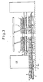
- Figure 3 illustrates a spinning frame to which the present invention is applied.
- a plurality of spindles 7 and intermediate pegs 8 are arranged in upper and lower rows, respectively, on a spindle rail 9 ⁇ extending in the lengthwise direction of the frame, and a pair of guide covers 10 are provided below the spindle rail 9 along the row of spindles 7.
- the guide cover 10 is adjacent at one end (left end in Fig. 1) to a feed or removal conveyor 5, and at the other end, to a deflection rail (not shown). Note, as this construction has no relation to the present invention, and thus a further explanation thereof will not be given.
- a bracket 2 projects from the frame 1 and holds a pair of rails 14 having a U-shaped cross-section opposite to each other with a narrow gap therebetween.
- the guide cover 10 has an L-shaped cross-section and is fixed by screws to the side of the respective rail 14 so that a lengthwise extending space is formed between the upper surface of the rail 14 and the lower surface of the guide cover 10 for displacing the peg-trays 13.
- the peg-tray 13 is molded from a plastic material and has a disc-like body having a peg 13a fixed on the upper side thereof for insertingly holding a bobbin, and a recess 13b formed on the lower side thereof.
- An upper gap is formed between the guide covers 10 at the upper portion thereof, to allow the peg-tray 13 to pass while restricting the width-wise position of the peg-tray.
- a concave 2a is formed on the bracket 2 in correspondence to a lower gap between the guide covers 10 at the lower portion thereof, through which is extended a driving bar 3, having a U-shaped cross-section, in a lengthwise direction of the spinning frame 1.
- a downward projecting bracket 3a is fixed in the vicinity of the end area of the driving bar 3, to which is connected a piston rod 16a of a horizontal power cylinder 16 by a pin. 17 through an adjustable turnbuckle 18.
- the cylinder 16 drives the piston rod 16a in a reciprocable manner at a stroke longer than the spindle pitch of the spinning frame, and accordingly, when the cylinder 16 is operated, the driving bar 3 is displaced in the lengthwise direction in. a reciprocable manner by a predetermined stroke.
- a plurality of positioning stops 4 are fixed by screws to the driving bar 3 at a pitch equal to a span of the spinning frame (see Fig. 1 and 5), and as shown in Fig. 4, the positioning stops 4 are provided with a pair of vertical slots 4a, 4b in the shape of a parallelopipedon, and a horizontal pin 4c is provided across the respective slots 4a, 4b.
- a tray-positioning bar 23 is provided between each adjacent stop 4 and is loosely fitted to the slots 4a, 4b by a guide portion 23b formed at the opposite ends thereof, so that an up-down movement of the guide portion 23b is allowed within a predetermined range.
- a number of saw teeth-like engagement projections 23a equal to the number of spindles 7 arranged between one span of the spinning frame are provided on the upper portion of the respective tray-positioning bar 23 at a pitch equal to the spindle pitch of the spinning frame, as shown in Fig. 1.
- the engagement projection 23a has an engagement surface projected vertically from the tray-positioning bar 23 and engageable with the recess 13b of the peg-tray 13, and is rearwardly inclined from the top of the engagement surface.
- a blade spring 19 is secured on the upper side of the driving bar 3, to bias the tray-positioning bar 23 upward.
- This blade spring may be replaced by another resilient means such as a coil spring, etc.
- the tray-positioning bar 23 is positioned at the leftmost end thereof by a vertical wall forming a'bottom surface of the right-side slot 4a of the positioning stop 4, while being prevented by the pin 4c from removal from the slot 4a. Accordingly, the rightmost end of the tray-positioning bar 23 confronts a vertical wall of the slot 4b of the preceding stop 4 with a gap therebetween.
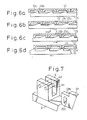
- Figure 6 (a) illustraterates an initial positional relationship between a row of peg-trays 13 and the tray-positioning bar 23, in which the respective projection 23a enters the engagement recess 13b of the corresponding peg-tray 13 and remains there while confronting the right-side inner wall of the recess 13b with a predetermined gap therebetween.
- the respective peg-tray 13 occupies a position corresponding to that of the spindle of the spinning frame.
- the projection 23a of the tray-positioning bar 23 abuts the right-side inner wall of the recess 13b, as shown in Fig. 6 (b), and pushes the peg-tray 13 forward as the driving bar 3 moves further to the right.
- the respective peg-tray 13 occupies a new position forwarded by one spindle pitch from the initial position when the driving bar 3 reaches the foremost point of the stroke. If an outer diameter of the peg-tray 13 is made smaller by than the positioning pitch, i.e., spindle pitch, a gap 6 exists between each adjacent peg-tray 3, as shown in the drawing.
- the driving bar 3 is moved by a rearward stroke to drive the tray-positioning bar 23 to the left in the drawing.
- the tray-positioning bar 23 is pushed down against the biasing force of the blade spring 19, because the inclined projection 23a is pushed by the left inner wall of the recess 13b of the peg-tray 13, whereby the projection 23a is allowed to pass under the peg-tray 13 as shown in Fig. 6 (d) and finally return to the position illustrated in Fig. 6 (a).
- FIG. 7 An alternative to the above positioning stop is shown in Fig. 7, in which, instead of the pair of vertical slots 4a, 4b, only one vertical slot 4d is formed in the stop 4 and a pair of parallel pins 4c are across the same.
- a vertically elongated aperture 23c is formed at the respective end area of the bar 23, and the respective pin 4c is loosely fitted to the aperture 23c so that a position of the tray-positioning bar 23 in the lengthwise direction is restricted by the pin 4c while allowing the up-down movement of the bar 23 within a predetermined range.
- the present invention is applicable not only to bobbin transportation in a spinning frame but also to the entire field of bobbin transportation in which bobbins are arranged in series at a predetermined pitch, such as in a twisting frame or a draw-twister.
Landscapes
- Engineering & Computer Science (AREA)
- Mechanical Engineering (AREA)
- Textile Engineering (AREA)
- Spinning Or Twisting Of Yarns (AREA)
Abstract
Dispositif de transfert de bobines chargées et non chargées pour métiers à filer, dans lequel des plateaux à chevilles (13), dont chacun est pourvu d'une cheville d'insertion de bobine (13a) au niveau de sa surface supérieure et d'un évidement de verrouillage (13b) au niveau de sa surface inférieure, sont transférés par rangées sur un chemin de transfert situé le long du côté avant d'une rangée de broches (7) d'un métier à filer. Le long dudit chemin de transfert est montée une barre d'entraînement (3) destinée à se déplacer vers l'avant et vers l'arrière de manière intermittente dans le sens de transfert de la bobine avec une course plus importante que le pas des broches du métier à filer. Sur toute la longueur de la barre d'entraînement (3) est formée linéairement une barre de positionnement de plateau (23) sur laquelle sont ménagés une pluralité d'éléments en saillie de verrouillage (23a) pouvant s'engager dans les évidements de verrouillage (13b) dans les plateaux à chevilles (13), lesdits éléments étant placés à des intervalles réguliers N (N étant un nombre naturel) fois plus grands que le pas des broches. La barre de positionnement de plateau (23) est supportée sur la barre d'entraînement (3) de sorte que la barre de positionnement (23) puisse être déplacée verticalement àl'aide d'un ressort (19), et également vers l'avant et vers l'arrière en fonction des mouvements vers l'avant et vers l'arrière de la barre d'entraînement (3). Lorsque cette dernière est déplacée vers l'avant, les éléments en saillie de verrouillage (23a) de la barre de positionnement de plateau (23) s'engagent dans les plateaux à chevilles opposés (13), de sorte que les plateaux à chevilles (13) se déplacent vers l'avant sur une distance correspondant à la longueur d'un plateau à chevilles. Lorsque la barre d'entraînement (3) se déplace vers l'arrière, les plateaux à chevilles (13) se dégagent des éléments en saillie de verrouillage (23a) sous l'action du ressort, de sorte qu'uniquement la barre de positionnement de plateau (23) est
Applications Claiming Priority (2)
| Application Number | Priority Date | Filing Date | Title |
|---|---|---|---|
| JP9047/88U | 1988-01-27 | ||
| JP904788U JPH052623Y2 (fr) | 1988-01-27 | 1988-01-27 |
Publications (2)
| Publication Number | Publication Date |
|---|---|
| EP0371134A1 true EP0371134A1 (fr) | 1990-06-06 |
| EP0371134A4 EP0371134A4 (en) | 1990-09-05 |
Family
ID=11709728
Family Applications (1)
| Application Number | Title | Priority Date | Filing Date |
|---|---|---|---|
| EP19890901740 Withdrawn EP0371134A4 (en) | 1988-01-27 | 1989-01-27 | Apparatus for transferring loaded and non-loaded bobbins for spinning machines |
Country Status (3)
| Country | Link |
|---|---|
| EP (1) | EP0371134A4 (fr) |
| JP (1) | JPH052623Y2 (fr) |
| WO (1) | WO1989007164A1 (fr) |
Family Cites Families (4)
| Publication number | Priority date | Publication date | Assignee | Title |
|---|---|---|---|---|
| JPS439463Y1 (fr) * | 1964-09-07 | 1968-04-24 | ||
| JPS57161133A (en) * | 1981-03-30 | 1982-10-04 | Howa Mach Ltd | Cop and bobbin conveyor in spinning frame |
| JPS6382285A (ja) * | 1986-09-20 | 1988-04-13 | Murata Mach Ltd | トレイの移送装置 |
| US4813222A (en) * | 1987-04-09 | 1989-03-21 | Kabushiki Kaisha Toyoda Jidoshokki Seisakusho | System for transferring full and empty bobbins from and to a textile machine such as a ring spinning frame |
-
1988
- 1988-01-27 JP JP904788U patent/JPH052623Y2/ja not_active Expired - Lifetime
-
1989
- 1989-01-27 EP EP19890901740 patent/EP0371134A4/en not_active Withdrawn
- 1989-01-27 WO PCT/JP1989/000076 patent/WO1989007164A1/fr not_active Ceased
Also Published As
| Publication number | Publication date |
|---|---|
| JPH052623Y2 (fr) | 1993-01-22 |
| WO1989007164A1 (fr) | 1989-08-10 |
| EP0371134A4 (en) | 1990-09-05 |
| JPH01114682U (fr) | 1989-08-02 |
Similar Documents
| Publication | Publication Date | Title |
|---|---|---|
| US4444303A (en) | Vibratory feeding work station module and system | |
| EP0286037B1 (fr) | Système pour transférer des bobines pleines et vides de et à une machine textile, par exemple un métier à filer à anneau | |
| EP0682133B1 (fr) | Dispositif guide-fil de tricotage dans un métier à tricoter rectiligne | |
| US4875572A (en) | Tray transfer device | |
| US3468407A (en) | Device for unloading a transfer case containing textile coils | |
| JP4900070B2 (ja) | 精紡機におけるボビン搬送装置 | |
| JPH0748683Y2 (ja) | 紡機における満・空ボビン移送装置 | |
| JPH03124823A (ja) | 空チューブを精紡位置に準備し、満ボビンを精紡位置から搬出するための搬送装置 | |
| WO1989007164A1 (fr) | Dispositif de transfert de bobines chargees et non chargees pour metiers a filer | |
| US5170618A (en) | Spinning mill overhead conveyor system having common drive for cleaner and bobbin carriers | |
| JP2894003B2 (ja) | 紡機における満・空ボビン搬送装置 | |
| KR910007565B1 (ko) | 정방기등에 있어서 만보빈과 공보빈의 이송장치 | |
| JPH0441190Y2 (fr) | ||
| EP0796552B1 (fr) | Procede et dispositif pour deplacer et, en particulier, remplacer des cartes a substrats imprimes dans une machine de montage de composants electroniques | |
| CN222573570U (zh) | 输送装置 | |
| JP2535868B2 (ja) | 精紡機等における満・空ボビン移送装置 | |
| JPH03206134A (ja) | 紡績機 | |
| JPS6335732B2 (fr) | ||
| JPH0949129A (ja) | 紡機における満・空ボビン搬送方法及び装置 | |
| JPH0238694B2 (ja) | Bobinisosochinohojiguichihoseisochi | |
| JP2513200B2 (ja) | 精紡機等における空ボビン位置決め方法 | |
| JP2539424Y2 (ja) | 紡機における満・空ボビン搬送装置 | |
| JPH0748684Y2 (ja) | 紡機における満・空ボビン移送装置 | |
| JPH09132828A (ja) | 紡機におけるボビン搬送方法及び搬送装置 | |
| JPH04174727A (ja) | 紡機における満・空ボビン移送装置の移送異常検知方法 |
Legal Events
| Date | Code | Title | Description |
|---|---|---|---|
| PUAI | Public reference made under article 153(3) epc to a published international application that has entered the european phase |
Free format text: ORIGINAL CODE: 0009012 |
|
| 17P | Request for examination filed |
Effective date: 19890924 |
|
| AK | Designated contracting states |
Kind code of ref document: A1 Designated state(s): CH DE IT LI |
|
| A4 | Supplementary search report drawn up and despatched |
Effective date: 19900716 |
|
| AK | Designated contracting states |
Kind code of ref document: A4 Designated state(s): CH DE IT LI |
|
| STAA | Information on the status of an ep patent application or granted ep patent |
Free format text: STATUS: THE APPLICATION IS DEEMED TO BE WITHDRAWN |
|
| 18D | Application deemed to be withdrawn |
Effective date: 19920801 |