EP0372448B1 - Optisches Modul mit integriertem Isolator für die Kopplung eines Halbleiterlasers an einen Wellenleiter - Google Patents
Optisches Modul mit integriertem Isolator für die Kopplung eines Halbleiterlasers an einen Wellenleiter Download PDFInfo
- Publication number
- EP0372448B1 EP0372448B1 EP89122313A EP89122313A EP0372448B1 EP 0372448 B1 EP0372448 B1 EP 0372448B1 EP 89122313 A EP89122313 A EP 89122313A EP 89122313 A EP89122313 A EP 89122313A EP 0372448 B1 EP0372448 B1 EP 0372448B1
- Authority
- EP
- European Patent Office
- Prior art keywords
- rotator
- laser
- plane
- guide
- polarization
- Prior art date
- Legal status (The legal status is an assumption and is not a legal conclusion. Google has not performed a legal analysis and makes no representation as to the accuracy of the status listed.)
- Expired - Lifetime
Links
- 230000003287 optical effect Effects 0.000 title claims description 35
- 230000008878 coupling Effects 0.000 title claims description 12
- 238000010168 coupling process Methods 0.000 title claims description 12
- 238000005859 coupling reaction Methods 0.000 title claims description 12
- 239000004065 semiconductor Substances 0.000 title claims description 6
- 239000000835 fiber Substances 0.000 claims abstract description 62
- 239000013078 crystal Substances 0.000 claims abstract description 11
- 230000010287 polarization Effects 0.000 claims description 37
- 230000002452 interceptive effect Effects 0.000 claims 2
- 239000013307 optical fiber Substances 0.000 abstract description 5
- 238000003780 insertion Methods 0.000 description 8
- 230000037431 insertion Effects 0.000 description 8
- 235000020004 porter Nutrition 0.000 description 6
- 230000005540 biological transmission Effects 0.000 description 5
- 238000009413 insulation Methods 0.000 description 5
- 230000008033 biological extinction Effects 0.000 description 4
- 238000001514 detection method Methods 0.000 description 4
- 230000001427 coherent effect Effects 0.000 description 3
- 239000002223 garnet Substances 0.000 description 3
- 230000003071 parasitic effect Effects 0.000 description 3
- 241001644893 Entandrophragma utile Species 0.000 description 2
- PEDCQBHIVMGVHV-UHFFFAOYSA-N Glycerine Chemical compound OCC(O)CO PEDCQBHIVMGVHV-UHFFFAOYSA-N 0.000 description 2
- XEEYBQQBJWHFJM-UHFFFAOYSA-N Iron Chemical compound [Fe] XEEYBQQBJWHFJM-UHFFFAOYSA-N 0.000 description 2
- 238000010521 absorption reaction Methods 0.000 description 2
- 238000012550 audit Methods 0.000 description 2
- 230000033228 biological regulation Effects 0.000 description 2
- 238000005516 engineering process Methods 0.000 description 2
- 238000002955 isolation Methods 0.000 description 2
- 230000005693 optoelectronics Effects 0.000 description 2
- 244000045947 parasite Species 0.000 description 2
- 229910000938 samarium–cobalt magnet Inorganic materials 0.000 description 2
- 230000035945 sensitivity Effects 0.000 description 2
- 238000003466 welding Methods 0.000 description 2
- 241000287107 Passer Species 0.000 description 1
- 241001080024 Telles Species 0.000 description 1
- 230000003667 anti-reflective effect Effects 0.000 description 1
- 230000000903 blocking effect Effects 0.000 description 1
- 238000010276 construction Methods 0.000 description 1
- 238000010586 diagram Methods 0.000 description 1
- 235000021183 entrée Nutrition 0.000 description 1
- 238000002474 experimental method Methods 0.000 description 1
- 229910052742 iron Inorganic materials 0.000 description 1
- 230000005415 magnetization Effects 0.000 description 1
- 238000004519 manufacturing process Methods 0.000 description 1
- 238000005259 measurement Methods 0.000 description 1
- 239000002184 metal Substances 0.000 description 1
- 229910052751 metal Inorganic materials 0.000 description 1
- 229920006395 saturated elastomer Polymers 0.000 description 1
Images


Classifications
-
- G—PHYSICS
- G02—OPTICS
- G02F—OPTICAL DEVICES OR ARRANGEMENTS FOR THE CONTROL OF LIGHT BY MODIFICATION OF THE OPTICAL PROPERTIES OF THE MEDIA OF THE ELEMENTS INVOLVED THEREIN; NON-LINEAR OPTICS; FREQUENCY-CHANGING OF LIGHT; OPTICAL LOGIC ELEMENTS; OPTICAL ANALOGUE/DIGITAL CONVERTERS
- G02F1/00—Devices or arrangements for the control of the intensity, colour, phase, polarisation or direction of light arriving from an independent light source, e.g. switching, gating or modulating; Non-linear optics
- G02F1/01—Devices or arrangements for the control of the intensity, colour, phase, polarisation or direction of light arriving from an independent light source, e.g. switching, gating or modulating; Non-linear optics for the control of the intensity, phase, polarisation or colour
- G02F1/09—Devices or arrangements for the control of the intensity, colour, phase, polarisation or direction of light arriving from an independent light source, e.g. switching, gating or modulating; Non-linear optics for the control of the intensity, phase, polarisation or colour based on magneto-optical elements, e.g. exhibiting Faraday effect
- G02F1/093—Devices or arrangements for the control of the intensity, colour, phase, polarisation or direction of light arriving from an independent light source, e.g. switching, gating or modulating; Non-linear optics for the control of the intensity, phase, polarisation or colour based on magneto-optical elements, e.g. exhibiting Faraday effect used as non-reciprocal devices, e.g. optical isolators, circulators
-
- G—PHYSICS
- G02—OPTICS
- G02B—OPTICAL ELEMENTS, SYSTEMS OR APPARATUS
- G02B6/00—Light guides; Structural details of arrangements comprising light guides and other optical elements, e.g. couplings
- G02B6/24—Coupling light guides
- G02B6/42—Coupling light guides with opto-electronic elements
- G02B6/4201—Packages, e.g. shape, construction, internal or external details
- G02B6/4204—Packages, e.g. shape, construction, internal or external details the coupling comprising intermediate optical elements, e.g. lenses, holograms
- G02B6/4207—Packages, e.g. shape, construction, internal or external details the coupling comprising intermediate optical elements, e.g. lenses, holograms with optical elements reducing the sensitivity to optical feedback
- G02B6/4208—Packages, e.g. shape, construction, internal or external details the coupling comprising intermediate optical elements, e.g. lenses, holograms with optical elements reducing the sensitivity to optical feedback using non-reciprocal elements or birefringent plates, i.e. quasi-isolators
-
- G—PHYSICS
- G02—OPTICS
- G02B—OPTICAL ELEMENTS, SYSTEMS OR APPARATUS
- G02B6/00—Light guides; Structural details of arrangements comprising light guides and other optical elements, e.g. couplings
- G02B6/24—Coupling light guides
- G02B6/42—Coupling light guides with opto-electronic elements
- G02B6/4201—Packages, e.g. shape, construction, internal or external details
- G02B6/4219—Mechanical fixtures for holding or positioning the elements relative to each other in the couplings; Alignment methods for the elements, e.g. measuring or observing methods especially used therefor
- G02B6/422—Active alignment, i.e. moving the elements in response to the detected degree of coupling or position of the elements
- G02B6/4225—Active alignment, i.e. moving the elements in response to the detected degree of coupling or position of the elements by a direct measurement of the degree of coupling, e.g. the amount of light power coupled to the fibre or the opto-electronic element
-
- G—PHYSICS
- G02—OPTICS
- G02B—OPTICAL ELEMENTS, SYSTEMS OR APPARATUS
- G02B6/00—Light guides; Structural details of arrangements comprising light guides and other optical elements, e.g. couplings
- G02B6/24—Coupling light guides
- G02B6/26—Optical coupling means
- G02B6/27—Optical coupling means with polarisation selective and adjusting means
- G02B6/2706—Optical coupling means with polarisation selective and adjusting means as bulk elements, i.e. free space arrangements external to a light guide, e.g. polarising beam splitters
- G02B6/2713—Optical coupling means with polarisation selective and adjusting means as bulk elements, i.e. free space arrangements external to a light guide, e.g. polarising beam splitters cascade of polarisation selective or adjusting operations
Definitions
- the present invention relates to an optical head comprising a semiconductor laser and ensuring its coupling to a light guide.
- the guide to be coupled consists of an optical fiber.
- the fiber to be coupled is typically a single-mode fiber.
- the optoelectronic sources used in these networks must have high performance. In particular, their line width must be very small. This is why these sources are currently constituted by lasers with distributed resonators called "DFB laser". Unfortunately, the latter have a damaging sensitivity to parasitic optical reflections which are difficult to avoid such as, for example, backscattering in the fiber and reflections at the level of non-optimized connections. The optical replenishments resulting from these reflections can disturb essential characteristics of the source such as monochromaticity, noise of relative intensity (RIN) etc ... which can penalize the system, or even prevent its proper functioning (rate of 'asymptotic errors greater than 10 ⁇ 9).
- RIN noise of relative intensity
- a known arrangement consists in integrating in the head an optical isolator capable of stopping the light which results from parasitic reflections.
- a disadvantage of these known heads is that they consist of an optical system with four elements (1st lens - rotator-2nd lens - polarizer) or with three elements (lens - rotator - polarizer) inserted between the laser and the fiber. This leads to great difficulty in implementation (positioning and adjustment of these different parts to ensure a minimum insertion loss and sufficient insulation).
- Another drawback is that the numerous interfaces encountered by light in the optical head tend to increase the proportion of light reflected back to the laser.
- the present invention aims in particular to simplify the construction and adjustment of an optical head with integrated isolator, and / or to reduce the size of this head as well as the number of interfaces capable of creating parasitic retroreflections.
- An optical head comprises the above-mentioned common elements and, for the purposes indicated above, it is characterized in that said final polarizer is a polarizing guide constituted by a section of light guide connected to said guide to be coupled , the light being injected by said lens into said final polarizing guide.
- This polarizing guide is for example constituted by a polarizing fiber.
- This polarizing fiber is preferably fixed to a front wall of said housing.
- a first optical head can be produced according to the present invention by comprising only the elements mentioned above, that is to say, in particular, a single rotator. It can be used with advantage in certain coherent detection transmission networks.
- optical isolation is required. It is typically greater than 35 dB. In some cases 50 to 60 dB of insulation may be required.
- They may for example include the laser, a first focusing lens, the first rotator, at least one intermediate polarizer, the second rotator, a final polarizer of the same type as the intermediate polarizer, and a second focusing lens.
- a second optical head can be produced according to the present invention by including, like this second known optical head, a second rotator preceded by an intermediate polarizer, while having, with respect to this second known head, the same advantages as the first head according to the present invention by compared to the first known head previously mentioned.
- Figure 1 shows a principle view of the first known head previously mentioned.
- FIG. 2 represents the optical elements of a first head according to the invention.
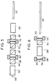
- FIG. 3 represents a cross section of the polarizing fiber of this latter head.
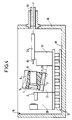
- FIG. 4 represents a section of this same head by a longitudinal vertical plane.
- FIG. 5 represents a principle view of the second known head previously mentioned.
- FIG. 6 represents a principle view of the second head according to the invention mentioned above.
- Figure 7 shows a section of the latter head by a longitudinal vertical plane.
- the rotator crystal 4 and the magnet 6 constitute said rotator which is a Faraday rotator.
- An axial recess 7 of this magnet extends in said longitudinal direction.
- This crystal is fixed opposite the laser 2 in a rear part of a sleeve 5 disposed in this recess.
- the focusing lens 8 is fixed in a front part of this sleeve opposite the polarizing fiber 10. This rotator and this lens are thus integrated in an intermediate block.
- the operation is as follows:
- the polarized light emitted by the laser 2 undergoes a rotation of 45 ° from its plane of polarization as it passes through the rotator.
- the lens 8 makes it possible to form the image of the laser spot on the entry face of the polarizing fiber which is oriented so that its passing axis is coincident with the plane of polarization of the incident light.
- the light reflected on the first connectors or at the end of the line is polarized after passing through the polarizing fiber. It undergoes the passage of the Faraday rotator a 45 ° rotation of its plane of polarization in the same direction as previously, which leads to a return of light on the laser in TM mode, configuration in which we do not observe any noise rise.
- a typical insulation of 25 dB is obtained.
- the polarizing fiber 10 comprises a metal insert M extending between its core C and its optical sheath G to absorb waves having a polarization perpendicular to said plane of output polarization.
- this insert is absent in a front section 11 of this polarizing fiber near this weld. It generally seems preferable that this insert be absent in the vicinity of an optical connection area even when the connection is made other than by welding.
- the assembly is carried out as follows, first outside the housing: the lens 8 and the rotator crystal 4 are brazed in the sleeve 5 which is itself introduced into the recess 7 of the magnet permanent 6.
- the assembly is fixed to the intermediate pallet 22 and the latter is fixed to the laser pallet 20 carrying the laser 2 after controlled adjustment by measuring the optical coupling.
- the polarizing fiber 10 is placed inside a tube 26.
- the set of laser pallets 20 and intermediate 22 is moved in X and Y relative to the fiber pallet 24 using a micromanipulator, still with optical coupling measurement.
- the tube 26 it is placed in a V-shaped groove in the fiber pallet 24 and it is likewise moved in Z and in rotation around its axis of direction Z.
- the tube 26 is welded with a YAG laser to the fiber pallet.
- the fiber and intermediate pallets are fixed in optimal position by YAG laser welding.
- the front end of the fiber 10 protruding from the tube 26 is then bent and introduced from the interior of the housing 16 into an outlet barrel 28 passing through a front wall 30 of this housing.
- the pallets 20, 22 and 24 are fixed to the floor 18 for example by means of a thermal regulation module 32.
- the tube 26 carried by the pallet 24 is short enough to be contained in the housing.
- the operation is as follows:
- the beam of polarized light emitted by the laser undergoes a first rotation of 45 ° from its plane of polarization after passing through the first rotator 204, 206.
- the lens 208 makes it possible to form the image of the laser spot on the entry face of the polarizing fiber 210.
- the polarizing 244 of the "Banning" type has its passing axis oriented on the vibration coming from the first rotator.
- the light undergoes a second polarization rotation when the second Faraday rotator 240, 246 passes (which brings it to 90 ° from its initial plane of polarization).
- the light is finally focused on the input face of the polarizing fiber, which is oriented so that its passing axis is coincident with the plane of polarization of the incident light.
- the light reflected on the first connectors, or at the end of the line, is polarized after passing through the polarizing fiber.
- the residual light, the plane of polarization is parallel to the passing axis of polarizer 244, sees its plane of polarization rotated again by 45 ° and returns polarized according to the TM mode of the laser, a configuration in which a very low sensitivity to phase noise is observed.
- said rotator is a Faraday rotator consisting of a thin blade of a rotator crystal 204, 240 and a permanent magnet 206, 246 of tubular shape forming an axial recess 207, 242 which extends in said longitudinal direction.
- the thin blade 204 of the first rotator is fixed in a rear part of a sleeve 205 provided in the recess 207 of this first rotator and is arranged opposite the laser 202 with an obliquity with respect to the useful light beam.
- the lens focusing 208 is fixed in a front part of this sleeve opposite the second intermediate block.
- the thin blade 240 of the second rotator is fixed in a front part of a sleeve 245 provided in the recess 242 of this second rotator and is arranged opposite the polarizing fiber 210; the intermediate polarizer 244 is a Banning polarizer fixed in a rear part of this sleeve opposite the focusing lens 208.
- the assembly is carried out as follows, first outside the housing: the lens 208 and the rotator crystal 204 are brazed in the sleeve 205 which is itself introduced into the recess 207 of the magnet permanent 206; the polarizer 244 and the rotator crystal 240 are fixed in the sleeve 245 which is itself introduced into the recess 242 of the permanent magnet 246.
- the first intermediate block is fixed to the intermediate pallet 222 and the latter is fixed to the laser pallet 220 carrying the laser 202 after controlled adjustment by measuring the optical coupling.
- the second intermediate block is disposed in a notch 250 provided for this purpose on the intermediate pallet 222 and is fixed to the latter after adjustment in rotation about its axis, controlled by measuring the optical insulation obtained for a light backscattered in the direction of the laser.
- the polarizing fiber 210 is placed inside a tube 226.
- the assembly in the housing 216 of the assembly thus produced is carried out in a similar manner to the assembly in the housing 16 of the assembly obtained in the case of the optical head illustrated in FIG. 4.
- the polarizing fiber 210 which is not surrounded by tube 226 that over a short length situated inside the housing 216, thus passes through an outlet barrel 228 crossing the front wall 230 of the housing 216 and the pallets 220, 222 and 224 are fixed to the floor 218 for example by means of '' a 232 thermal regulation module.
Landscapes
- Physics & Mathematics (AREA)
- General Physics & Mathematics (AREA)
- Optics & Photonics (AREA)
- Nonlinear Science (AREA)
- Engineering & Computer Science (AREA)
- Power Engineering (AREA)
- Optical Couplings Of Light Guides (AREA)
- Optical Head (AREA)
- Semiconductor Lasers (AREA)
Claims (6)
- Optischer Kopf mit integriertem Isolator zum Ankoppeln eines Halbleiterlasers an einen Lichtleiter, der einen anzukoppelnden Lichtleiter bildet und Teil eines Fernmeldesystems mit Lichtleitern ist, wobei der Kopf aufweist:- ein Gehäuse (16), das eine Längsrichtung mit einer Vorderseite und einer Hinterseite besitzt,- den Halbleiterlaser (2), der in dem Gehäuse angeordnet ist, um ein Nutzlichtstrahlbündel in Längsrichtung nach vorne auszusenden, wobei das Bündel eine Polarisationsebene besitzt, die gemäß einer Ebene, Laserpolarisationsebene genannt, ausgerichtet ist,- einen Polarisationsrotator (4, 6), der in dem Gehäuse vor dem Laser angeordnet ist, um die Polarisationsebene des Bündels um etwa 45° in eine Richtung zu drehen, so daß die Ebene in einer Austrittspolarisationsebene orientiert wird,- eine Fokussierungslinse (8), die in dem Gehäuse vor dem Laser angeordnet ist, um das Strahlenbündel in den Eingang des Lichtleiters einzugeben, der den Anfang des anzukoppelnden Lichtleiters bildet,- und einen Polarisator, der zwischen dem Rotator und dem in Richtung der Austrittspolarisationsebene orientierten anzukoppelnden Lichtleiter angeordnet ist, derart, daß er das vom Laser kommende Nutzlicht durchläßt und das gesamte nach hinten reflektierte Störlicht gemäß der Austrittspolarisationsebene polarisiert, damit der Rotator anschließend die Polarisationsebene dieses Störlichts um etwa 45° in die genannte Richtung dreht, und damit dieses Licht am Laser nur mit einer Polarisationsebene ankommt, die im wesentlichen senkrecht zur Laserpolarisationsebene verläuft,- wobei dieser optische Kopf dadurch gekennzeichnet ist, daß der Polarisator ein polarisierender Lichtleiter (10) ist, der aus einem Lichtwellenleiterstück besteht, das an den anzukoppelnden Lichtleiter (14) angeschlossen ist, wobei das Licht durch die Linse in den polarisierenden Lichtleiter eingegeben wird.
- Kopf nach Anspruch 1, dadurch gekennzeichnet, daß der Rotator ein Faraday-Rotator ist, der aus einem dünnen Plättchen eines Rotatorkristalls (4) und einem rohrförmigen Permanentmagneten (6) besteht, der eine axiale Aussparung (7) bildet, die sich in der genannten Längsrichtung erstreckt, wobei sich das Plättchen in einem hinteren Abschnitt der Aussparung gegenüber dem Laser (2) befestigt ist, während die Fokussierungslinse (8) in einem vorderen Abschnitt dieser Aussparung gegenüber dem polarisierenden Lichtleiter (10) befestigt ist.
- Kopf nach Anspruch 2, dadurch gekennzeichnet, daß das Gehäuse (16) einen Boden (18) besitzt, der von hinten nach vorne trägt:- eine Laserpalette (20), die den Laser (2) trägt und eine quer verlaufende ebene Vorderseite besitzt,- eine Zwischenpalette (22), die den Permanentmagneten (6) trägt, wobei die Palette eine quer verlaufende ebene Hinterseite, die gegen die Vorderseite der Laserpalette anliegt, und eine quer verlaufende ebene Vorderseite besitzt,- und eine Lichtleiterpalette (24), die ein Ende des polarisierenden Lichtleiters (10) trägt, wobei diese Palette eine gegen die Vorderseite der Zwischenpalette anliegende quer verlaufende ebene Hinterseite besitzt, so daß das Einstellen und das Einhalten der relativen Positionen der Paletten erleichtert wird,- wobei das Gehäuse weiter eine Vorderwand (30) besitzt, die den polarisierenden Lichtleiter in einem Abstand von seinem Ende trägt.
- Kopf nach Anspruch 1, dadurch gekennzeichnet, daß er weiter aufweist:- einen zweiten Rotator (240, 246), der im Gehäuse (216) zwischen dem zuvor erwähnten Rotator, der dann einer ersten Rotator (204, 206) bildet, und dem zuvor erwähnten Polarisator, der dann einen Ausgangspolarisator (210) bildet, angeordnet ist, um erneut die Polarisationsebene des Strahlenbündels um etwa 45° in die genannte Richtung zu drehen, so daß diese Ebene in die Austrittspolaristionsebene ausgerichtet wird,- und einen Zwischenpolarisator (244), der zwischen dem ersten und dem zweiten Rotator angeordnet ist, um selektiv das aus dem ersten Rotator austretende Nutzlicht durchzulassen.
- Kopf nach Anspruch 4, dadurch gekennzeichnet, daß das Gehäuse (216) einen Boden (218) besitzt, der von hinten nach vorne trägt:- eine Laserpalette (220) zum Tragen des Lasers (202),- eine Zwischenpalette (222) für einen ersten Zwischenblock, der den ersten Rotator (204, 206) und die Fokussierungslinse (208) enthält, und einen zweiten Zwischenblock, der den Zwischenpolarisator (244) und den zweiten Rotator (240, 246) enthält,- und eine Lichtleiterpalette (224) für ein Ende des polarisierenden Lichtleiters (210),- wobei das Gehäuse weiter eine Vorderwand (230) besitzt, die den polarisierenden Lichtleiter im Abstand von seinem Ende trägt.
- Kopf nach Anspruch 5, dadurch gekennzeichnet, daß in jedem der Zwischenblöcke der Rotator ein Faraday-Rotator ist, der aus einem dünnen Plättchen eines Rotatorkristalls (204, 240) und einem rohrförmigen Permanentmagneten (206, 246) besteht, der eine axiale Ausnehmung (207, 242) bildet, die sich in der genannten Längsrichtung erstreckt, wobei das dünne Plättchen (204) des ersten Rotators in einem hinteren Abschnitt der Ausnehmung des ersten Rotators gegenüber dem Laser (202) befestigt ist, mit einer relativ zum Nutzlichtbündel verlaufenden Schräglage, während die Fokussierungslinse (208) in einem vorderen Abschnitt der Aussparung gegenüber dem zweiten Zwischenblock befestigt ist, wobei das dünne Plättchen (240) des zweiten Rotators in einem vorderen Abschnitt der Ausnehmung (242) des zweiten Rotators gegenüber der polarisierenden Lichtleitfaser (210) befestigt ist, während der Zwischenpolarisator (244) ein Banning-Polarisator ist, der in einem hinteren Abschnitt der Ausnehmung gegenüber der Fokussierungslinse (208) befestigt ist.
Applications Claiming Priority (4)
| Application Number | Priority Date | Filing Date | Title |
|---|---|---|---|
| FR8816221A FR2640437B1 (fr) | 1988-12-09 | 1988-12-09 | Tete optique a isolateur integre pour le couplage d'un laser semi-conducteur a une fibre |
| FR8816221 | 1988-12-09 | ||
| FR8910057 | 1989-07-26 | ||
| FR8910057A FR2650446B2 (fr) | 1988-12-09 | 1989-07-26 | Tete optique a isolateur integre pour le couplage d'un laser semi-conducteur a une fibre |
Publications (2)
| Publication Number | Publication Date |
|---|---|
| EP0372448A1 EP0372448A1 (de) | 1990-06-13 |
| EP0372448B1 true EP0372448B1 (de) | 1994-06-08 |
Family
ID=26227040
Family Applications (1)
| Application Number | Title | Priority Date | Filing Date |
|---|---|---|---|
| EP89122313A Expired - Lifetime EP0372448B1 (de) | 1988-12-09 | 1989-12-04 | Optisches Modul mit integriertem Isolator für die Kopplung eines Halbleiterlasers an einen Wellenleiter |
Country Status (9)
| Country | Link |
|---|---|
| US (1) | US5121451A (de) |
| EP (1) | EP0372448B1 (de) |
| JP (1) | JPH02212806A (de) |
| AT (1) | ATE107043T1 (de) |
| AU (1) | AU616580B2 (de) |
| CA (1) | CA2004939C (de) |
| DE (1) | DE68915962T2 (de) |
| ES (1) | ES2057078T3 (de) |
| FR (1) | FR2650446B2 (de) |
Families Citing this family (18)
| Publication number | Priority date | Publication date | Assignee | Title |
|---|---|---|---|---|
| US4981335A (en) * | 1989-10-17 | 1991-01-01 | At&T Bell Laboratories | Optical package arrangement with reduced reflections |
| FR2678393B1 (fr) * | 1991-06-28 | 1995-02-10 | Cit Alcatel | Dispositif a fibre optique transversalement anisotrope et son procede de fabrication. |
| US5268922A (en) * | 1991-10-31 | 1993-12-07 | International Business Machines Corporation | Laser diode assembly |
| JPH05267775A (ja) * | 1992-03-19 | 1993-10-15 | Nec Corp | 半導体レーザ装置 |
| GB2268813B (en) * | 1992-07-13 | 1995-04-19 | Integrated Optical Components | Packaged optical devices |
| JPH0688926A (ja) * | 1992-07-24 | 1994-03-29 | Tdk Corp | 光アイソレータ付き光ファイバ端子とその組立方法 |
| FR2698453B1 (fr) * | 1992-11-24 | 1994-12-23 | Thomson Csf | Procédé de couplage d'une fibre optique avec un composant optoélectronique et dispositif de couplage. |
| EP0733222A1 (de) * | 1993-12-10 | 1996-09-25 | Jds Fitel Inc. | Optisch nichtreziproke bauelemente |
| JPH07261121A (ja) * | 1994-03-18 | 1995-10-13 | Tdk Corp | 光アイソレータ付き光ファイバ端子 |
| GB9412528D0 (en) * | 1994-06-22 | 1994-08-10 | Bt & D Technologies Ltd | Packaged optical amplifier assembly |
| US6449091B1 (en) * | 1996-12-03 | 2002-09-10 | Jds Fitel Inc. | Optical isolator |
| US6901221B1 (en) | 1999-05-27 | 2005-05-31 | Jds Uniphase Corporation | Method and apparatus for improved optical elements for vertical PCB fiber optic modules |
| US6213651B1 (en) | 1999-05-26 | 2001-04-10 | E20 Communications, Inc. | Method and apparatus for vertical board construction of fiber optic transmitters, receivers and transceivers |
| US20030002128A1 (en) * | 2001-06-14 | 2003-01-02 | Shin-Etsu Chemical Co., Ltd | Optical isolator |
| JP3997795B2 (ja) * | 2002-02-22 | 2007-10-24 | 住友金属鉱山株式会社 | 半導体モジュールの製造方法 |
| WO2011009303A1 (zh) * | 2009-07-22 | 2011-01-27 | 武汉华工正源光子技术有限公司 | 防止半导体光放大器管芯激射的封装方法 |
| US9787054B2 (en) * | 2015-05-05 | 2017-10-10 | Sifotonics Technologies Co., Ltd. | Optical package providing efficient coupling between DFB-LD and silicon PIC edge couplers with low return loss |
| CN113296201B (zh) * | 2021-05-21 | 2022-07-22 | 福建中科光芯光电科技有限公司 | 一种光学组件及光模块及工作方法 |
Family Cites Families (11)
| Publication number | Priority date | Publication date | Assignee | Title |
|---|---|---|---|---|
| JPS60184225A (ja) * | 1984-03-01 | 1985-09-19 | Shojiro Kawakami | 光フアイバ型アイソレ−タ |
| JPS60202415A (ja) * | 1984-03-27 | 1985-10-12 | Hoya Corp | 光アイソレ−タ |
| GB2189900B (en) * | 1986-04-22 | 1989-11-29 | Plessey Co Plc | Optical fibre devices |
| US4712866A (en) * | 1986-07-24 | 1987-12-15 | Andrew Corporation | Indium-clad fiber-optic polarizer |
| JPS6384185A (ja) * | 1986-09-29 | 1988-04-14 | Matsushita Electric Ind Co Ltd | 光アイソレ−タ付半導体レ−ザモジユ−ル |
| US4966444A (en) * | 1987-01-14 | 1990-10-30 | Siemens Aktiengesellschaft | Feedback-free optical arrangement for converting polarized laser emissions into a convergent beam |
| JPS63228121A (ja) * | 1987-03-17 | 1988-09-22 | Seiko Instr & Electronics Ltd | 光フアイバ光アイソレ−タ |
| JPS63226987A (ja) * | 1987-03-17 | 1988-09-21 | Nec Corp | 光アイソレ−タ内蔵型半導体レ−ザ装置 |
| AU605029B2 (en) * | 1988-03-25 | 1991-01-03 | Telstra Corporation Limited | Magneto-optic device |
| US4893890A (en) * | 1988-05-04 | 1990-01-16 | Lutes George F | Low-loss, high-isolation, fiber-optic isolator |
| US4867524A (en) * | 1988-09-08 | 1989-09-19 | United Technologies Corporation | Metallic bond for mounting of optical fibers to integrated optical chips |
-
1989
- 1989-07-26 FR FR8910057A patent/FR2650446B2/fr not_active Expired - Lifetime
- 1989-12-04 AT AT89122313T patent/ATE107043T1/de not_active IP Right Cessation
- 1989-12-04 DE DE68915962T patent/DE68915962T2/de not_active Expired - Fee Related
- 1989-12-04 ES ES89122313T patent/ES2057078T3/es not_active Expired - Lifetime
- 1989-12-04 EP EP89122313A patent/EP0372448B1/de not_active Expired - Lifetime
- 1989-12-06 AU AU45955/89A patent/AU616580B2/en not_active Ceased
- 1989-12-07 JP JP1318721A patent/JPH02212806A/ja active Pending
- 1989-12-08 CA CA002004939A patent/CA2004939C/fr not_active Expired - Fee Related
- 1989-12-11 US US07/448,436 patent/US5121451A/en not_active Expired - Fee Related
Also Published As
| Publication number | Publication date |
|---|---|
| AU616580B2 (en) | 1991-10-31 |
| DE68915962T2 (de) | 1994-09-22 |
| CA2004939C (fr) | 1999-08-24 |
| FR2650446A2 (fr) | 1991-02-01 |
| US5121451A (en) | 1992-06-09 |
| DE68915962D1 (de) | 1994-07-14 |
| ATE107043T1 (de) | 1994-06-15 |
| EP0372448A1 (de) | 1990-06-13 |
| CA2004939A1 (fr) | 1990-06-09 |
| AU4595589A (en) | 1990-06-14 |
| ES2057078T3 (es) | 1994-10-16 |
| FR2650446B2 (fr) | 1994-08-19 |
| JPH02212806A (ja) | 1990-08-24 |
Similar Documents
| Publication | Publication Date | Title |
|---|---|---|
| EP0372448B1 (de) | Optisches Modul mit integriertem Isolator für die Kopplung eines Halbleiterlasers an einen Wellenleiter | |
| EP0205359B1 (de) | Optoelektronischer Zweirichtungsbauteil, der einen optischen Koppler bildet | |
| FR2756936A1 (fr) | Module de filtre optique et amplificateur optique l'utilisant | |
| EP2089943B1 (de) | Lasersystem mit picosekundenimpulsemission | |
| EP0581671A1 (de) | Verfahren zur Ankopplung einer Glasfaser an einen optischen Baustein auf einem gemeinsamen Substrat | |
| EP0520902B1 (de) | Vorrichtung mit transversal-anisotroper optischer Faser und Verfahren für ihre Herstellung | |
| FR2916310A1 (fr) | Laser a puce pulse | |
| EP0977327A1 (de) | Freiraumlaser mit selbstjustierter Auskoppelfaser | |
| FR2640437A1 (fr) | Tete optique a isolateur integre pour le couplage d'un laser semi-conducteur a une fibre | |
| FR2860599A1 (fr) | Dispositif de couplage optique d'une fibre monomode multi-coeurs, et procede de fabrication correspondant | |
| FR2549246A1 (fr) | Isolateur optique | |
| EP1745531B1 (de) | Strahlungsemitter mit geneigtem pumpstrahl | |
| EP0795778A1 (de) | Nichtlineare optische Signalverarbeitungseinrichtung | |
| FR2686423A1 (fr) | Boitier polarimetrique de mesure de l'angle de faraday. | |
| FR3159841A1 (fr) | Isolateur optique à atténuation liée à la polarisation auto-compensée | |
| EP0766111A1 (de) | Optischer Stecker und sein Herstellungsverfahren | |
| EP4390483A1 (de) | Optische kopplungsvorrichtung mit holographischer beugungsstruktur | |
| EP4614200A1 (de) | Optischer koppler mit polarisationstrennung | |
| EP1322978A1 (de) | Einkoppelvorrichtung für eine optische faser und zugehöriges herstellungsverfahren | |
| FR2833417A1 (fr) | Resonateur optique en anneau sans surface, appareil de telecommunication et/ou de projection video correspondant | |
| FR2876191A1 (fr) | Procede et dispositif de couplage de composants optiques | |
| FR2890496A1 (fr) | Procede de production d'un faisceau laser de puissance et dispositif de mise en oeuvre | |
| FR3142310A1 (fr) | Système de telecommunication optique en espace libre | |
| WO2005015698A1 (fr) | Source laser de puissance a grande finesse spectrale | |
| EP0802435A1 (de) | Apparat zur Bestimmung des Kopplungsoptimums zwischen einer optoelektronischen Komponente und optischen Monomoden-Faser und dessen Einbau in ein Modul |
Legal Events
| Date | Code | Title | Description |
|---|---|---|---|
| PUAI | Public reference made under article 153(3) epc to a published international application that has entered the european phase |
Free format text: ORIGINAL CODE: 0009012 |
|
| AK | Designated contracting states |
Kind code of ref document: A1 Designated state(s): AT BE CH DE ES FR GB IT LI NL SE |
|
| 17P | Request for examination filed |
Effective date: 19901210 |
|
| 17Q | First examination report despatched |
Effective date: 19920709 |
|
| GRAA | (expected) grant |
Free format text: ORIGINAL CODE: 0009210 |
|
| AK | Designated contracting states |
Kind code of ref document: B1 Designated state(s): AT BE CH DE ES FR GB IT LI NL SE |
|
| REF | Corresponds to: |
Ref document number: 107043 Country of ref document: AT Date of ref document: 19940615 Kind code of ref document: T |
|
| GBT | Gb: translation of ep patent filed (gb section 77(6)(a)/1977) |
Effective date: 19940610 |
|
| REF | Corresponds to: |
Ref document number: 68915962 Country of ref document: DE Date of ref document: 19940714 |
|
| ITF | It: translation for a ep patent filed | ||
| REG | Reference to a national code |
Ref country code: ES Ref legal event code: FG2A Ref document number: 2057078 Country of ref document: ES Kind code of ref document: T3 |
|
| EAL | Se: european patent in force in sweden |
Ref document number: 89122313.3 |
|
| PLBE | No opposition filed within time limit |
Free format text: ORIGINAL CODE: 0009261 |
|
| STAA | Information on the status of an ep patent application or granted ep patent |
Free format text: STATUS: NO OPPOSITION FILED WITHIN TIME LIMIT |
|
| 26N | No opposition filed | ||
| PGFP | Annual fee paid to national office [announced via postgrant information from national office to epo] |
Ref country code: CH Payment date: 20001120 Year of fee payment: 12 |
|
| PGFP | Annual fee paid to national office [announced via postgrant information from national office to epo] |
Ref country code: AT Payment date: 20001122 Year of fee payment: 12 |
|
| PGFP | Annual fee paid to national office [announced via postgrant information from national office to epo] |
Ref country code: BE Payment date: 20001130 Year of fee payment: 12 |
|
| PGFP | Annual fee paid to national office [announced via postgrant information from national office to epo] |
Ref country code: ES Payment date: 20001218 Year of fee payment: 12 |
|
| PG25 | Lapsed in a contracting state [announced via postgrant information from national office to epo] |
Ref country code: AT Free format text: LAPSE BECAUSE OF NON-PAYMENT OF DUE FEES Effective date: 20011204 |
|
| PG25 | Lapsed in a contracting state [announced via postgrant information from national office to epo] |
Ref country code: LI Free format text: LAPSE BECAUSE OF NON-PAYMENT OF DUE FEES Effective date: 20011231 Ref country code: CH Free format text: LAPSE BECAUSE OF NON-PAYMENT OF DUE FEES Effective date: 20011231 Ref country code: BE Free format text: LAPSE BECAUSE OF NON-PAYMENT OF DUE FEES Effective date: 20011231 |
|
| REG | Reference to a national code |
Ref country code: GB Ref legal event code: IF02 |
|
| BERE | Be: lapsed |
Owner name: ALCATEL CIT Effective date: 20011231 |
|
| REG | Reference to a national code |
Ref country code: CH Ref legal event code: PL |
|
| PGFP | Annual fee paid to national office [announced via postgrant information from national office to epo] |
Ref country code: GB Payment date: 20021128 Year of fee payment: 14 |
|
| PGFP | Annual fee paid to national office [announced via postgrant information from national office to epo] |
Ref country code: NL Payment date: 20021130 Year of fee payment: 14 |
|
| PGFP | Annual fee paid to national office [announced via postgrant information from national office to epo] |
Ref country code: SE Payment date: 20021202 Year of fee payment: 14 |
|
| PG25 | Lapsed in a contracting state [announced via postgrant information from national office to epo] |
Ref country code: ES Free format text: LAPSE BECAUSE OF NON-PAYMENT OF DUE FEES Effective date: 20021205 |
|
| PGFP | Annual fee paid to national office [announced via postgrant information from national office to epo] |
Ref country code: FR Payment date: 20021206 Year of fee payment: 14 |
|
| PGFP | Annual fee paid to national office [announced via postgrant information from national office to epo] |
Ref country code: DE Payment date: 20021218 Year of fee payment: 14 |
|
| PG25 | Lapsed in a contracting state [announced via postgrant information from national office to epo] |
Ref country code: GB Free format text: LAPSE BECAUSE OF NON-PAYMENT OF DUE FEES Effective date: 20031204 |
|
| PG25 | Lapsed in a contracting state [announced via postgrant information from national office to epo] |
Ref country code: SE Free format text: LAPSE BECAUSE OF NON-PAYMENT OF DUE FEES Effective date: 20031205 |
|
| REG | Reference to a national code |
Ref country code: ES Ref legal event code: FD2A Effective date: 20030113 |
|
| PG25 | Lapsed in a contracting state [announced via postgrant information from national office to epo] |
Ref country code: NL Free format text: LAPSE BECAUSE OF NON-PAYMENT OF DUE FEES Effective date: 20040701 Ref country code: DE Free format text: LAPSE BECAUSE OF NON-PAYMENT OF DUE FEES Effective date: 20040701 |
|
| GBPC | Gb: european patent ceased through non-payment of renewal fee |
Effective date: 20031204 |
|
| EUG | Se: european patent has lapsed | ||
| PG25 | Lapsed in a contracting state [announced via postgrant information from national office to epo] |
Ref country code: FR Free format text: LAPSE BECAUSE OF NON-PAYMENT OF DUE FEES Effective date: 20040831 |
|
| NLV4 | Nl: lapsed or anulled due to non-payment of the annual fee |
Effective date: 20040701 |
|
| REG | Reference to a national code |
Ref country code: FR Ref legal event code: ST |
|
| PG25 | Lapsed in a contracting state [announced via postgrant information from national office to epo] |
Ref country code: IT Free format text: LAPSE BECAUSE OF NON-PAYMENT OF DUE FEES;WARNING: LAPSES OF ITALIAN PATENTS WITH EFFECTIVE DATE BEFORE 2007 MAY HAVE OCCURRED AT ANY TIME BEFORE 2007. THE CORRECT EFFECTIVE DATE MAY BE DIFFERENT FROM THE ONE RECORDED. Effective date: 20051204 |