EP0802435A1 - Apparat zur Bestimmung des Kopplungsoptimums zwischen einer optoelektronischen Komponente und optischen Monomoden-Faser und dessen Einbau in ein Modul - Google Patents
Apparat zur Bestimmung des Kopplungsoptimums zwischen einer optoelektronischen Komponente und optischen Monomoden-Faser und dessen Einbau in ein Modul Download PDFInfo
- Publication number
- EP0802435A1 EP0802435A1 EP97460013A EP97460013A EP0802435A1 EP 0802435 A1 EP0802435 A1 EP 0802435A1 EP 97460013 A EP97460013 A EP 97460013A EP 97460013 A EP97460013 A EP 97460013A EP 0802435 A1 EP0802435 A1 EP 0802435A1
- Authority
- EP
- European Patent Office
- Prior art keywords
- sleeve
- orifice
- bench
- base
- leg
- Prior art date
- Legal status (The legal status is an assumption and is not a legal conclusion. Google has not performed a legal analysis and makes no representation as to the accuracy of the status listed.)
- Withdrawn
Links
- 230000008878 coupling Effects 0.000 title claims abstract description 42
- 238000010168 coupling process Methods 0.000 title claims abstract description 42
- 238000005859 coupling reaction Methods 0.000 title claims abstract description 42
- 239000013307 optical fiber Substances 0.000 title claims description 14
- 230000005693 optoelectronics Effects 0.000 title abstract description 11
- 238000009434 installation Methods 0.000 title 1
- 230000003287 optical effect Effects 0.000 claims abstract description 27
- 239000004065 semiconductor Substances 0.000 claims description 9
- 238000004026 adhesive bonding Methods 0.000 claims description 4
- 239000004020 conductor Substances 0.000 claims 1
- 239000000835 fiber Substances 0.000 abstract description 7
- 238000000034 method Methods 0.000 description 16
- 239000003292 glue Substances 0.000 description 8
- 238000009792 diffusion process Methods 0.000 description 7
- 230000005540 biological transmission Effects 0.000 description 6
- 239000000853 adhesive Substances 0.000 description 5
- 230000001070 adhesive effect Effects 0.000 description 5
- 238000006116 polymerization reaction Methods 0.000 description 5
- 238000003466 welding Methods 0.000 description 4
- 230000005679 Peltier effect Effects 0.000 description 3
- 238000003780 insertion Methods 0.000 description 3
- 230000037431 insertion Effects 0.000 description 3
- 238000004519 manufacturing process Methods 0.000 description 3
- 238000004806 packaging method and process Methods 0.000 description 3
- 238000007747 plating Methods 0.000 description 3
- 230000003068 static effect Effects 0.000 description 3
- 239000004593 Epoxy Substances 0.000 description 2
- BQCADISMDOOEFD-UHFFFAOYSA-N Silver Chemical compound [Ag] BQCADISMDOOEFD-UHFFFAOYSA-N 0.000 description 2
- PNEYBMLMFCGWSK-UHFFFAOYSA-N aluminium oxide Inorganic materials [O-2].[O-2].[O-2].[Al+3].[Al+3] PNEYBMLMFCGWSK-UHFFFAOYSA-N 0.000 description 2
- 230000033228 biological regulation Effects 0.000 description 2
- 238000001514 detection method Methods 0.000 description 2
- 238000005470 impregnation Methods 0.000 description 2
- 230000001939 inductive effect Effects 0.000 description 2
- 229910052709 silver Inorganic materials 0.000 description 2
- 239000004332 silver Substances 0.000 description 2
- 230000035882 stress Effects 0.000 description 2
- 230000032683 aging Effects 0.000 description 1
- 230000003321 amplification Effects 0.000 description 1
- 230000000712 assembly Effects 0.000 description 1
- 238000000429 assembly Methods 0.000 description 1
- 230000000593 degrading effect Effects 0.000 description 1
- 238000000151 deposition Methods 0.000 description 1
- 238000013461 design Methods 0.000 description 1
- 230000006866 deterioration Effects 0.000 description 1
- 238000006073 displacement reaction Methods 0.000 description 1
- 230000000694 effects Effects 0.000 description 1
- 230000005489 elastic deformation Effects 0.000 description 1
- 238000002474 experimental method Methods 0.000 description 1
- 238000003754 machining Methods 0.000 description 1
- 239000000463 material Substances 0.000 description 1
- 229910052751 metal Inorganic materials 0.000 description 1
- 239000002184 metal Substances 0.000 description 1
- 238000003199 nucleic acid amplification method Methods 0.000 description 1
- 238000005457 optimization Methods 0.000 description 1
- 230000010287 polarization Effects 0.000 description 1
- 238000012545 processing Methods 0.000 description 1
- 239000011347 resin Substances 0.000 description 1
- 229920005989 resin Polymers 0.000 description 1
- 238000012552 review Methods 0.000 description 1
- 239000000523 sample Substances 0.000 description 1
- 238000007789 sealing Methods 0.000 description 1
- 239000007787 solid Substances 0.000 description 1
- 230000002269 spontaneous effect Effects 0.000 description 1
- 238000003892 spreading Methods 0.000 description 1
- 238000012360 testing method Methods 0.000 description 1
Images


Classifications
-
- G—PHYSICS
- G02—OPTICS
- G02B—OPTICAL ELEMENTS, SYSTEMS OR APPARATUS
- G02B6/00—Light guides; Structural details of arrangements comprising light guides and other optical elements, e.g. couplings
- G02B6/24—Coupling light guides
- G02B6/42—Coupling light guides with opto-electronic elements
- G02B6/4201—Packages, e.g. shape, construction, internal or external details
- G02B6/4219—Mechanical fixtures for holding or positioning the elements relative to each other in the couplings; Alignment methods for the elements, e.g. measuring or observing methods especially used therefor
- G02B6/422—Active alignment, i.e. moving the elements in response to the detected degree of coupling or position of the elements
-
- G—PHYSICS
- G02—OPTICS
- G02B—OPTICAL ELEMENTS, SYSTEMS OR APPARATUS
- G02B6/00—Light guides; Structural details of arrangements comprising light guides and other optical elements, e.g. couplings
- G02B6/24—Coupling light guides
- G02B6/42—Coupling light guides with opto-electronic elements
- G02B6/4201—Packages, e.g. shape, construction, internal or external details
- G02B6/4219—Mechanical fixtures for holding or positioning the elements relative to each other in the couplings; Alignment methods for the elements, e.g. measuring or observing methods especially used therefor
- G02B6/4236—Fixing or mounting methods of the aligned elements
- G02B6/4239—Adhesive bonding; Encapsulation with polymer material
Definitions
- the present invention relates to an apparatus used in a method for finding the optimum coupling between an opto-electronic component and at least one single-mode optical fiber, optionally via an intermediate optic, then in a method of assembling in a module the opto component. -electronics and fiber. It also relates to methods making it possible to join certain parts of the apparatus.
- the technical field concerned is that of fiber optic telecommunications using opto-electronic modules based on the use of active semiconductor components.
- single-mode optical fiber is increasingly used as a transmission medium in long distance links.
- Optical systems use opto-electronic modules performing transmission, amplification and detection functions. These opto-electronic modules are, for the most part, made from semiconductor components. The coupling of these active components must be optimized either to inject the maximum optical power in single-mode optical fiber, i.e. to receive the maximum optical power. The assembly must then be fixed in position, then mounted as a module using means which guarantee the conservation of the alignment on a submicron scale.
- the mismatch between the circular Gaussian mode of the fiber and the elliptical mode of the active component requires very precise positioning of the various elements to be coupled. For example, compared to the optimal coupling position, a deviation of 0.6 ⁇ m along the OX (or OY) axis, perpendicular to the OZ optical axis, can cause a loss of 1 dB.
- the assembly technique must allow a solid and reliable fixing of the various mechanical and optical elements, without inducing deformations of mechanical or thermal origin which risk degrading the initial performance of the coupling. Then, the various mechanical and optical elements thus assembled are to be mounted in a housing.
- Nd: YAG lasers used are classified in class IV and their operation in pulsed mode releases significant powers, for example of a few kW. Drastic precautions for use are essential to guarantee the safety of personnel.
- An object of the present invention is to use a method of finding the optimum coupling in dynamic mode using a semi-automatic bench and, to remedy the drawbacks mentioned above, to provide, as equipment, a set of means to be adapted to the bench for coupling, then assembly of an opto-electronic component and an optical fiber, possibly via an intermediate optic.
- each sleeve is pierced with an orifice passing through the upper part of its cylindrical wall and has a circular groove on its internal surface.
- the flange of each sleeve has an upper face having a chamfer and an external face, square side, in which are hollowed one or more grooves communicating with the bottom of the chamfer.
- the external face of the flange of each sleeve is applied against the external face of the jamb of the bracket, or of a jamb of the double-square. by pushing fingers housed in the mobile part of the bench and subjected to the action of calibrated springs.
- the intermediate optics are fixed in each sleeve by gluing.
- the external face of the flange of each sleeve is fixed to the external face of the leg of the square, or of a leg of the double-square by gluing.
- the bonding operation which is planned according to the two preceding characteristics represents a significant progress compared to the prior art of spot welding carried out using an Nd: YAG laser mentioned above.
- a bonding operation is simple, does not pose temperature problems and does not requires no precautions for use to guarantee the safety of personnel.
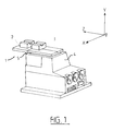
- the bench 1, shown in perspective in FIG. 1, consists of a fixed cradle 2 and a movable carriage 3 which are respectively fixed on the upper parts of a plate 4.
- the cradle 2 is static and is connected to the chassis of the plate 4 by via a fixing bracket 5; on the cradle 4, are mounted the parts intended to receive and house the active component, including the temperature regulation and electrical supply circuits of the active component, while it is on the bench 1.
- the mobile carriage 3 is mounted on the movable platform of the plate 4; on the carriage 3, are mounted the parts intended to receive the coupling optics which extend the optical fiber.
- the plate 4 also includes three potentiometers Px, Py and Pz which conventionally make it possible to execute, with respect to the fixed cradle 2, limited movements of the mobile carriage 3 along three rectangular axes OX, OY and OZ.
- Px, Py and Pz which conventionally make it possible to execute, with respect to the fixed cradle 2, limited movements of the mobile carriage 3 along three rectangular axes OX, OY and OZ.
- a command managed by a computer is used to execute limited movements of the mobile carriage, the potentiometers being represented only for the record.
- plate 4 corresponds to the Light Line F-603.00 model from PHYSIK INSTRUMENTE sold in France by the company POLYTEC Pl / RMP; it is a micro-positioning stage with three precision axes OX, OY and OZ.
- the plate 4 comprises piezo-linear motors of the kind described in the document EP-A-624 912 A1. The reduced dimensions of this plate made it possible in particular to develop a very compact mechanical assembly.
- FIG. 2 shows an active component 6 mounted on a base 7, practically in the form of a parallelepiped, which is intended to be introduced into a housing 8 of a base support 9.
- the base support 9 is mounted, by means of shims not shown, on the static cradle 2, which also performs the temperature regulation function (Peltier effect module with CTN 10 Kilohms thermistor probe) and the electrical supplies of the active component required.
- Fig. 2 also shows an intermediate optic or coupling optic 10, composed of a cylindrical diode coupler 11 enclosing the end of a single-mode optical fiber 12, and a sleeve 13.
- the sleeve 13 is provided at one of its ends with a flange 14 which has a cylindrical hole 15 corresponding to the internal wall of the sleeve 13.
- the sleeve 13 and its flange 14 are provided for housing the free end of the diode coupler 11.
- the axis of the cylindrical diode coupler 11 is shown oriented along the axis OZ of a rectangular trihedron OXYZ and coincides with the axes of the sleeve 13 and of the hole 15.
- the free face 17 of the flange 14, on the opposite side with respect to the rest of the sleeve 13, has an external shape limited by two equal linear segments 18 and 19, substantially horizontal, connected by two arcs of a circle 20 and 21.
- the face 17 comprises a set of hollow grooves 22 to 24, the groove 22 being circular and the grooves 23 and 24 having the form of arcs of circles bounded by the linear segments 18 and 19.
- the upper face of the flange 14, corresponding to the upper segment 18, has a bevelled surface 25, oblique downwards and towards the free face 17, which has recessed parts giving access to the bottom of the upper parts of the grooves 22 to 24.
- the sleeve 13 has, as said above, an internal cylinder of the same diameter as the hole 15.
- the cylindrical wall of the sleeve 13 is pierced with a small orifice 26, the role of which will be seen below.
- the base support 9 has the general shape of a square formed by a thick base 27 and a leg 28.
- the leg 28 has a hole 29, in which the end of the diode coupler 11 is housed, with a diameter greater than that of the hole 15 of the flange 14, Immediately behind the leg 28, there is, drilled vertically in the base 27, the housing 8 whose internal dimensions correspond to the external dimensions of the base 7.
- the axis OZ corresponds to the maximum emission axis of the active component 6, once it is placed with the base 7 in the housing 8.
- the base 27 is pierced with two small smooth holes 30 and 31, and a tapped hole 32, these holes passing through the base 27 right through.
- the base 7 also has two small holes 33 and 34.
- the holes 30 and 33, on the one hand, and 31 and 34, on the other hand, are aligned by means of two precision pins 36 and 37 , and the base 7 is pressed against the reference face of the housing 8 by the screw 38 screwed into the hole 32.
- the base 27 has adequate vertical holes allowing it to be fixed by screws on the fixed cradle 2.
- FIG. 3 also appears the coupling optics 10, with its end in the sleeve 13 mounted on the movable carriage 3.
- the sleeve 13 is permanently pressed against the leg 28 of the base support 9 (even during the search phase of the maximum coupling) by the action of two pusher fingers 39, which have been represented symbolically in the exploded view of FIG. 2.
- the free ends of the pusher fingers 39, FIG. 4 are applied against the flange 14 of the sleeve 13, horizontally on either side of the axis OZ, while the other ends of the pusher fingers 39 are pushed by setting springs 40; the fingers 39 and the springs 40 are housed in the mobile carriage 3.
- All the electrical supplies are grouped together on a nine-pin socket 41, Fig. 3, located under the square.
- the contacts on the active component 6 are made by means of a tilting flap 42, provided with conventional metal latches coming to bear on the electrical supply zones arranged on the base 7.
- the tilting flap 42 and the flange of Erasable clamping allows rapid assembly and disassembly of the parts to be bound and linked.
- the search for the optimal coupling position is carried out by dynamic positioning of the coupling optics 10, which is integral with the mobile carriage 3 of the plate 4.
- the coupling optics 10, with the diode coupler 11, is placed opposite the active component 6 mounted by means of the base 8 on the base support 9, via the sleeve 3.
- the sleeve 13 is permanently pressed against the base support 9 by the action of the two pusher fingers 39.
- the axial load developed by the plate (8.5 N ) and the setting of the springs 40 are compatible to guarantee the initial performance of the plate 4, namely a positioning precision of 0.1 ⁇ m.
- the realization of a macro-optoelectronic module comprises three distinct phases: first, the coupling, second, the assembly of the various elements by technique of bonding (these two operations are carried out on the bench) and, thirdly, after polymerization of the adhesive, the packaging of the assembly which will now be described.
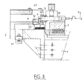
- the bonded assembly is placed in a housing 44, as shown in FIGS. 5 and 6.
- the section AA and the top view reveal the arrangement of the various elements inside the housing 44.
- the mounting is based on a module 45 with Peltier effect of 10 x 15 mm located on the bottom of the housing.
- the assembly is held in position by two fixing screws which pass through the bottom of the housing which serves as a heat sink, the screws are engaged with the base support 9.
- the complete assembly incorporates a double polarization "Tee” produced on an alumina with a thickness of 0.635 mm which is located on the top of the base support, and glued with silver epoxy.
- Tee double polarization
- optical component 6 was an optical transmitter, such as a laser diode, but the person skilled in the art will understand that the production of a receiving head can be made , using the same means, taking as an optical component a photodetector diode.
- FIG. 7 The exploded view of FIG. 7 relates to all of the means used to produce an optical amplifier.
- the mechanical assembly defined for the assembly of an optical amplifier presents analogies with the assembly previously described, as shown in the exploded view of FIG. 7.
- this assembly uses sleeves 13, identical to that of FIG. 2, and it repeats the same technique for fixing the base 7 to its support (pins 36, 37, plus screw 38).
- the base support 46 comprises a thick base 47 supplemented by two parallel legs 48 and 49, the part of the base 47 which is located between the legs 48 and 49 being suitably drilled vertically to form therein a recess 8 for receiving the base 7 of the active component 6.
- the base support 46 can be considered as the combination of two base supports 9, FIG. 2, which would have been placed face to face so that the holes 15 of the legs 48 and 49 can receive the ends of two aligned diode couplers 50 and 51 each provided with their sleeve 13.
- the realization of an optical amplifier is similar to that of an optical head. After coupling and bonding of the first sleeve 13 on the first leg 48, the assembly is removed from the bench 1 and reinstalled on the static cradle 2 to perform the same operations on the other side of the active component 6.
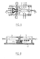
- the assembly ends with a casing, as shown in FIG. 8, various elements of an optical amplifier, in the case of a coupling produced by diode couplers.
- the various elements integrated into the housing are standard and identical to those used for mounting a transmission or reception head.
- Six isolated feedthroughs supply the Peltier module, the thermistor and the active component (+ laser and - laser).
- the housing offers the possibility of adding one or two modulation sockets, which are connected to the active component by a conventional alumina.
- optoelectronic modules have been produced having low assembly losses, as illustrated below in the case of the mounting of a laser emission head and an optical amplifier.
- the coupling and assembly of an emission head was carried out using a BH (Buried Heterostructure) type laser and an ISOWAVE commercial diode coupler (reference: 1-15-PTMLC.7, front distance 700 ⁇ m, insertion loss - 3 dB).
- the reference coupled power without plating the mechanical parts was 875 ⁇ W. Table 1 attached below shows the variation in the level of the module's output power, depending on the different assembly steps.
- the bonding assembly technique does not degrade the initial coupling performance, the final loss is close to the insertion loss of the diode coupler: the difference is less than 0.5 dB. It should be noted that in this particular case, the mounting in the housing has improved the performance: this is explained, on the one hand, by the mechanical stresses exerted on the end of the diode coupler by the closing sealing resin the housing and, on the other hand, by the deformation caused by an optimized tightening of the cover screws.
- the assembly technique was also validated by the realization of an optical amplifier module with semiconductor, the two couplings on the two faces of the component were carried out by ISOWAVE diode couplers, respectively presenting a measured insertion loss by the manufacturer 2.6 dB for side A and 2.3 dB for side B.
- the spontaneous emission power was identical for both sides of the component (1.7 mW)
- Table II shows the evolution of the output power of each face as a function of the different stages of production.
- the bonding technique makes it possible to obtain very low assembly losses, close to the intrinsic losses of the optics used.
- the use of an instant adhesive of low viscosity allows a good impregnation of the parts to be assembled.
- the nature of the glue used allows an easy implementation and a reduced execution time of this assembly phase, the polymerization of the adhesive occurs after 15 min.
- the experimental procedure used reproducibly retains the initial performance of the coupling, as confirmed by an aging test carried out on a transmission head, for more than 6000 hours.
Landscapes
- Physics & Mathematics (AREA)
- General Physics & Mathematics (AREA)
- Optics & Photonics (AREA)
- Optical Couplings Of Light Guides (AREA)
Applications Claiming Priority (2)
| Application Number | Priority Date | Filing Date | Title |
|---|---|---|---|
| FR9604986 | 1996-04-16 | ||
| FR9604986A FR2747479B1 (fr) | 1996-04-16 | 1996-04-16 | Appareillage pour recherche du couplage optimum entre un composant opto-electronique et une fibre optique monomode et pour leur assemblage dans un module |
Publications (1)
| Publication Number | Publication Date |
|---|---|
| EP0802435A1 true EP0802435A1 (de) | 1997-10-22 |
Family
ID=9491414
Family Applications (1)
| Application Number | Title | Priority Date | Filing Date |
|---|---|---|---|
| EP97460013A Withdrawn EP0802435A1 (de) | 1996-04-16 | 1997-03-24 | Apparat zur Bestimmung des Kopplungsoptimums zwischen einer optoelektronischen Komponente und optischen Monomoden-Faser und dessen Einbau in ein Modul |
Country Status (2)
| Country | Link |
|---|---|
| EP (1) | EP0802435A1 (de) |
| FR (1) | FR2747479B1 (de) |
Families Citing this family (1)
| Publication number | Priority date | Publication date | Assignee | Title |
|---|---|---|---|---|
| CN112505852B (zh) * | 2020-12-08 | 2022-07-15 | 武汉光谷信息光电子创新中心有限公司 | 一种硅基芯片调节装置、耦合装置及耦合方法 |
Citations (4)
| Publication number | Priority date | Publication date | Assignee | Title |
|---|---|---|---|---|
| EP0129048A2 (de) * | 1983-06-18 | 1984-12-27 | Alcatel N.V. | Vorrichtung zum spielfreien Verschieben von Objekten in einem Koordinatensystem |
| FR2661005A1 (fr) * | 1990-04-13 | 1991-10-18 | Thomson Csf | Dispositif d'alignement et de fixation d'une fibre optique devant un laser semiconducteur. |
| FR2698453A1 (fr) * | 1992-11-24 | 1994-05-27 | Thomson Csf | Procédé de couplage d'une fibre optique avec un composant optoélectronique et dispositif de couplage. |
| FR2702054A1 (fr) * | 1993-02-24 | 1994-09-02 | Cit Alcatel | Tête optique pour système de communication à fibre optique. |
-
1996
- 1996-04-16 FR FR9604986A patent/FR2747479B1/fr not_active Expired - Fee Related
-
1997
- 1997-03-24 EP EP97460013A patent/EP0802435A1/de not_active Withdrawn
Patent Citations (4)
| Publication number | Priority date | Publication date | Assignee | Title |
|---|---|---|---|---|
| EP0129048A2 (de) * | 1983-06-18 | 1984-12-27 | Alcatel N.V. | Vorrichtung zum spielfreien Verschieben von Objekten in einem Koordinatensystem |
| FR2661005A1 (fr) * | 1990-04-13 | 1991-10-18 | Thomson Csf | Dispositif d'alignement et de fixation d'une fibre optique devant un laser semiconducteur. |
| FR2698453A1 (fr) * | 1992-11-24 | 1994-05-27 | Thomson Csf | Procédé de couplage d'une fibre optique avec un composant optoélectronique et dispositif de couplage. |
| FR2702054A1 (fr) * | 1993-02-24 | 1994-09-02 | Cit Alcatel | Tête optique pour système de communication à fibre optique. |
Also Published As
| Publication number | Publication date |
|---|---|
| FR2747479A1 (fr) | 1997-10-17 |
| FR2747479B1 (fr) | 1998-05-07 |
Similar Documents
| Publication | Publication Date | Title |
|---|---|---|
| EP0158561B1 (de) | Verbindungsvorrichtung für eine optische Faser und eine Photoelement, Empfänger oder Sender; Verfahren zur Einstellung solcher Elemente | |
| FR2752623A1 (fr) | Procede de fabrication d'un dispositif de couplage optique collectif et dispositif obtenu par un tel procede | |
| FR2545617A1 (fr) | Structure de support pour la fixation de fibres optiques et de lentilles et procede pour leur preparation ainsi que dispositif les utilisant | |
| FR2871244A1 (fr) | Dispositif de couplage optique | |
| EP0372448B1 (de) | Optisches Modul mit integriertem Isolator für die Kopplung eines Halbleiterlasers an einen Wellenleiter | |
| FR2547661A1 (fr) | Procede et dispositif de raccordement d'une fibre optique avec un detecteur photosensible et le procede de mise en oeuvre | |
| CN101222115A (zh) | 半导体激光器模块 | |
| EP0481876B1 (de) | Justierverfahren der optischen Achsen von einer Faser und von einem optoelektronischen Bauelement und die mit diesem Verfahren hergestellte Vorrichtung | |
| EP0183124A1 (de) | Optische Lichtquelle | |
| FR2611388A1 (fr) | Module optique actif pour embase de connecteur | |
| EP0112211B1 (de) | Verfahren zum Ausrichten eines optoelektronischen Gerätes | |
| EP0094274A1 (de) | Verfahren zum Zusammensetzen einer optischen Vorrichtung mit einem Halbleiterlaser, Vorrichtung und Werkbank dafür | |
| CN104471457B (zh) | 光学模块及用于组装光学模块的方法 | |
| EP0802435A1 (de) | Apparat zur Bestimmung des Kopplungsoptimums zwischen einer optoelektronischen Komponente und optischen Monomoden-Faser und dessen Einbau in ein Modul | |
| US6736550B1 (en) | Housing for passively aligning an optical fiber with a lens | |
| US20050047475A1 (en) | Optical module | |
| EP4168838B1 (de) | Photonischer chip, verfahren zur montage eines optischen teils und des photonischen chips und daraus resultierendes photonisches bauelement | |
| EP0977327A1 (de) | Freiraumlaser mit selbstjustierter Auskoppelfaser | |
| US10185104B2 (en) | Optical receiver and method of assembling the same and providing rotational alignment | |
| US20090136178A1 (en) | Optical Assembly Connecting a Laser With Optical Fibre | |
| EP0129456A2 (de) | Verfahren und Vorrichtung zur Zentrierung einer optischen Faser relativ zu einer Linse in einem Stecker und so erhaltenes Verbindungselement | |
| FR3071327B1 (fr) | Procede et systeme d'alignement de l'axe optique d'un cable optique avec un composant optoelectronique | |
| FR2737310A1 (fr) | Procede et dispositif de couplage entre une fibre optique et un laser ou un photodetecteur | |
| Asbury et al. | Laser-welded packaging of a Nd: YAG laser for space applications | |
| CA2394929A1 (fr) | Composant hybride d'optocouplage |
Legal Events
| Date | Code | Title | Description |
|---|---|---|---|
| PUAI | Public reference made under article 153(3) epc to a published international application that has entered the european phase |
Free format text: ORIGINAL CODE: 0009012 |
|
| AK | Designated contracting states |
Kind code of ref document: A1 Designated state(s): DE GB |
|
| 17P | Request for examination filed |
Effective date: 19971202 |
|
| STAA | Information on the status of an ep patent application or granted ep patent |
Free format text: STATUS: THE APPLICATION IS DEEMED TO BE WITHDRAWN |
|
| 18D | Application deemed to be withdrawn |
Effective date: 19991001 |