EP0373680A2 - Méthode et appareil employant une palette avec un support de pièces à usiner détachable, pour la réalisation de parties de moteurs électriques - Google Patents
Méthode et appareil employant une palette avec un support de pièces à usiner détachable, pour la réalisation de parties de moteurs électriques Download PDFInfo
- Publication number
- EP0373680A2 EP0373680A2 EP89201042A EP89201042A EP0373680A2 EP 0373680 A2 EP0373680 A2 EP 0373680A2 EP 89201042 A EP89201042 A EP 89201042A EP 89201042 A EP89201042 A EP 89201042A EP 0373680 A2 EP0373680 A2 EP 0373680A2
- Authority
- EP
- European Patent Office
- Prior art keywords
- workpiece
- pallet
- engaging
- holder
- workpiece holder
- Prior art date
- Legal status (The legal status is an assumption and is not a legal conclusion. Google has not performed a legal analysis and makes no representation as to the accuracy of the status listed.)
- Granted
Links
- 238000000034 method Methods 0.000 title claims abstract description 9
- 238000004519 manufacturing process Methods 0.000 description 6
- 101001073193 Homo sapiens Pescadillo homolog Proteins 0.000 description 2
- 102100035816 Pescadillo homolog Human genes 0.000 description 2
- 101100243456 Arabidopsis thaliana PES2 gene Proteins 0.000 description 1
- 238000010586 diagram Methods 0.000 description 1
- 230000003534 oscillatory effect Effects 0.000 description 1
Images


Classifications
-
- H—ELECTRICITY
- H02—GENERATION; CONVERSION OR DISTRIBUTION OF ELECTRIC POWER
- H02K—DYNAMO-ELECTRIC MACHINES
- H02K15/00—Processes or apparatus specially adapted for manufacturing, assembling, maintaining or repairing of dynamo-electric machines
-
- Y—GENERAL TAGGING OF NEW TECHNOLOGICAL DEVELOPMENTS; GENERAL TAGGING OF CROSS-SECTIONAL TECHNOLOGIES SPANNING OVER SEVERAL SECTIONS OF THE IPC; TECHNICAL SUBJECTS COVERED BY FORMER USPC CROSS-REFERENCE ART COLLECTIONS [XRACs] AND DIGESTS
- Y10—TECHNICAL SUBJECTS COVERED BY FORMER USPC
- Y10T—TECHNICAL SUBJECTS COVERED BY FORMER US CLASSIFICATION
- Y10T29/00—Metal working
- Y10T29/49—Method of mechanical manufacture
- Y10T29/49002—Electrical device making
- Y10T29/49009—Dynamoelectric machine
-
- Y—GENERAL TAGGING OF NEW TECHNOLOGICAL DEVELOPMENTS; GENERAL TAGGING OF CROSS-SECTIONAL TECHNOLOGIES SPANNING OVER SEVERAL SECTIONS OF THE IPC; TECHNICAL SUBJECTS COVERED BY FORMER USPC CROSS-REFERENCE ART COLLECTIONS [XRACs] AND DIGESTS
- Y10—TECHNICAL SUBJECTS COVERED BY FORMER USPC
- Y10T—TECHNICAL SUBJECTS COVERED BY FORMER US CLASSIFICATION
- Y10T29/00—Metal working
- Y10T29/53—Means to assemble or disassemble
- Y10T29/5313—Means to assemble electrical device
- Y10T29/53143—Motor or generator
- Y10T29/53161—Motor or generator including deforming means
-
- Y—GENERAL TAGGING OF NEW TECHNOLOGICAL DEVELOPMENTS; GENERAL TAGGING OF CROSS-SECTIONAL TECHNOLOGIES SPANNING OVER SEVERAL SECTIONS OF THE IPC; TECHNICAL SUBJECTS COVERED BY FORMER USPC CROSS-REFERENCE ART COLLECTIONS [XRACs] AND DIGESTS
- Y10—TECHNICAL SUBJECTS COVERED BY FORMER USPC
- Y10T—TECHNICAL SUBJECTS COVERED BY FORMER US CLASSIFICATION
- Y10T29/00—Metal working
- Y10T29/53—Means to assemble or disassemble
- Y10T29/53435—Means to assemble or disassemble including assembly pallet
-
- Y—GENERAL TAGGING OF NEW TECHNOLOGICAL DEVELOPMENTS; GENERAL TAGGING OF CROSS-SECTIONAL TECHNOLOGIES SPANNING OVER SEVERAL SECTIONS OF THE IPC; TECHNICAL SUBJECTS COVERED BY FORMER USPC CROSS-REFERENCE ART COLLECTIONS [XRACs] AND DIGESTS
- Y10—TECHNICAL SUBJECTS COVERED BY FORMER USPC
- Y10T—TECHNICAL SUBJECTS COVERED BY FORMER US CLASSIFICATION
- Y10T29/00—Metal working
- Y10T29/53—Means to assemble or disassemble
- Y10T29/53539—Means to assemble or disassemble including work conveyor
- Y10T29/53543—Means to assemble or disassemble including work conveyor including transporting track
Definitions
- This invention relates to methods and apparatus for making electric motor parts (e.g., the stators and rotors for electric motors), and more particularly to pallet systems for supporting such parts during manufacture.
- electric motor parts e.g., the stators and rotors for electric motors
- the stators and rotors for electric motor parts are typically made on highly automated assembly lines. Each stator or rotor is typically conveyed along the assembly line by positioning it on a workpiece holder. Each workpiece holder is mounted on a pallet which is the element actually engaged by the conveyor system in order to support and convey the associated stator or rotor along the assembly line. Because precise positioning of the stator or rotor relative to the machine tools located along the assembly line is required, all elements of the workpiece support system must securely engage one another so that there is no looseness or "play" in the support system. On the other hand, most assembly lines must be able to manufacture more than one size or type of motor. It would therefore be desirable to have a workpiece support system which could readily adapt to supporting motor parts of different sizes and/or types.
- a pallet system including a pallet member having means for supporting and releasably engaging a workpiece holder, preferably at any one of a plurality of pallet-engaging sites on the workpiece holder.
- the workpiece holder also preferably has a plurality of workpiece-engaging sites, each of the workpiece-engaging sites being associated with a respective one of the pallet-engaging sites so that, when the workpiece holder is engaged by the pallet at a particular pallet-engaging site, the workpiece holder can engage a workpiece at the workpiece-engaging site associated with that pallet-engaging site.
- the pallet When the workpiece holder is engaged by the pallet, the pallet supports the workpiece holder very securely. However, a quick release connection is used between the pallet and the workpiece holder so that the workpiece holder can be quickly removed from the pallet and either repositioned on the pallet using a different pallet-engaging site or completely replaced by another workpiece holder. Apparatus for repositioning or replacing workpiece holders as described above is also disclosed.
- FIGS. 1 and 2 has a pallet 1 having a base plate 2 onto which is screwed a substantially cylindrical hollow part 3 which slidably receives a pin 4 urged downwardly by spring 5.
- the portion of pin 4 inside part 3 has a grooved or recessed part 6 with inclined sidewalls acting on ball 7 inside an opening 8 in cylindrical part 3.
- the workpiece holder comprises a double body 9, 10 constructed in two separate parts held together by screws 11. Each body has a flange 12, 13 to which pins 14, 17 and supports 15, 16 are screwed to hold a workpiece and avoid accidental rotary or oscillatory movements of the workpiece.
- the workpiece holder is adapted to hold an electric motor stator, but it will be apparent that the workpiece holder could be adapted to hold other parts such as an electric motor rotor.
- the central part of bodies 9 and 10 is shaped to fit into the boring of the type of stator it will carry when the relevant body is turned upwards on the pallet.
- the bodies 9 and 10 with their pins 14, 17 and supports 15, 16 are therefore typically designed to hold two stators of different dimensions. Therefore, when changing from one type of stator to the other, it is sufficient to rotate the part formed by bodies 9, 10 relative to pallet base 2.
- stator holder is automatically locked to the pallet because the inclined sidewalls of pin 4 (which is pushed downwardly by spring 5) push ball 7 outwardly of cylindrical part 3 into the hollow part 19 of body 9 (or 10) until the ball rests inside annular groove 18.
- Means (described below) at various assembly line stations are provided for push ing pin 4 up in order to disengage the stator holder from cylindrical part 3, thus permitting its rotation in order to present the opposite body designed to accommodate the other type of stator.
- FIGS. 3 and 4 show a device which can be placed at the start of an assembly line to rotate the double body 9, 10 as described above.
- the device includes a gripper 20, a rotating cylinder 21 and a linear unit 22.
- the device is normally in the upper position (shown in broken lines in FIG. 3). with gripper 20 open. Pallet 1 stops at a conveyor stop gate (not shown because entirely conventional and well known).
- Linear unit 22 goes down with the gripper jaws 23 of gripper 20 apart. (Alternatively, the same result could be achieved by horizontal movement of gripper 20 and cylinder 21.)
- Gripper jaws 23 close around the stator holder, the pins 24 and 25 of jaw 23 engaging openings in body 9, 10.
- Cylinder 26, located under the transport system pushes pin 4 upward, thereby disengaging body 9 (or 10) as explained above.
- Linear unit 22 moves upward, lifting up the stator holder.
- gripper 20 rotates 180 degrees.
- Linear unit 22 then goes down and lowers the grooved part 27 of the lower body onto part 3 on the pallet.
- Cylinder 26 then goes back down so that the stator holder is again locked to the pallet as described above.
- the present invention can also be advantageously employed in assembly lines or stators production lines featuring machines with automated re-tooling, i.e., with machines in which the tool parts designed for processing various workpieces are changed automatically.
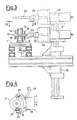
- double body 9, 10 may be changed as shown, for example, in FIG. 5.
- a manipulator with a double gripper is placed alongside the transport system together with a storage unit transporting the workpiece holders on supports fixed between two parallel transport chains.
- Gripper 28 is associated with the storage unit and is moved by pneumatic cylinder 30, which lowers gripper 28 so that it can grip the workpiece holder with the same pin system as gripper 20 shown in FIG. 4. Cylinder 30 then lifts the gripper up into the position shown in FIG. 5.
- gripper 33 carries out the same work as gripper 28, gripping workpiece holder 32 and lifting it up away from the pallet.
- arm 34 operated by a rod inside column 31 and rotated by the same rotating cylinder (not shown because straightforward) located under plate 35, rotates 180 degrees, thereby reversing the positions of grippers 33 and 28.
- Grippers 28 and 33 then respectively descend to the pallet and to the support on the storage unit, thereby reversing the positions of the workpiece holders.
- the store chains index in order to bring a new workpiece holder under the gripper.
- the pallet on the transport system moves on, leaving the place to another pallet with a workpiece holder to be changed.
- the workpiece holders on the pallets are locked in place in the same amnner as shown in FIG. 3; while on the storage unit, the workpiece holders are loosely fitted over a reference pin on the support.
- FIG. 6 shows part of an illustrative embodiment of an electric motor assembly line constructed in accordance with this invention.
- Endless conveyor 40 conveys pallets 1 in the direction indicated by arrows 42.
- Element 50 may be storage unit apparatus of the type shown in FIG. 5 for selectively replacing the workpiece holder on a pallet at position 1a.
- Element 52 may be workpiece holder inverter apparatus of the type shown in FIGS. 3 and 4 for selectively inverting the workpiece holder on a pallet at position 1c.
- an electric motor part 56 e.g., a stator or rotor supplied via conveyor 58 is put on the workpiece holder on pallet 1d by conventional element 54.
- Elements 50 and 52 are selectively operated to ensure that the pallet at position 1d contains the workpiece holder appropriate for holding a workpiece 56 and that that workpiece holder is also properly oriented for receiving such a workpiece.
- Conventional element 60 performs any conventional manufacturing step on the workpiece on the pallet at position 1f.
- Conventional element 62 performs another conventional manufacturing step on the workpiece on the pallet at position 1g.
- At position 1h, conventional element 62 removes the completed workpiece 56′ from the pallet and conveys it away via conveyor 66. The empty pallets and workpiece holders are returned to the start of the assembly line for reuse.
- each workpiece holder (abstracted as element WH in FIG. 7) includes two pallet-engaging sites PES1 and PES2 respectively associated with two workpiece-engaging sites WES1 and WES2, this is not necessarily the case, and the workpiece holders of this invention can have other numbers of pallet- and workpiece-engaging sites if desired.
- FIG. 8 shows a workpiece holder WH having only one pallet-engaging site PES1 and one opposite workpiece-engaging site WES1.
- Such workpiece holders could be used with apparatus of the type shown in FIG. 5 to enable an assembly line to process differently configured workpieces.
- FIG. 8 shows a workpiece holder WH having only one pallet-engaging site PES1 and one opposite workpiece-engaging site WES1.
- FIG. 9 shows a workpiece holder WH having three pallet-engaging sites PES1-PES3, each of which is associated with a respective one of three workpiece-engaging sites WES1-WES3.
- FIG. 10 shows a workpiece holder WH having four pallet-engaging sites PES1-PES4, each of which is associated with a respective one of four workpiece-engaging sites WES1-WES4.
Landscapes
- Engineering & Computer Science (AREA)
- Manufacturing & Machinery (AREA)
- Power Engineering (AREA)
- Automatic Assembly (AREA)
- Specific Conveyance Elements (AREA)
- Manufacture Of Motors, Generators (AREA)
- Jigs For Machine Tools (AREA)
- Feeding Of Workpieces (AREA)
- Manipulator (AREA)
- Relays Between Conveyors (AREA)
Applications Claiming Priority (2)
| Application Number | Priority Date | Filing Date | Title |
|---|---|---|---|
| IT8868113A IT1234229B (it) | 1988-12-16 | 1988-12-16 | Metodi ed apparecchiature per realizzare parti di motori elettrici impieganti pallets con supporto amovibile del pezzo in lavorazione |
| IT6811388 | 1988-12-16 |
Publications (3)
| Publication Number | Publication Date |
|---|---|
| EP0373680A2 true EP0373680A2 (fr) | 1990-06-20 |
| EP0373680A3 EP0373680A3 (fr) | 1991-06-12 |
| EP0373680B1 EP0373680B1 (fr) | 1994-11-30 |
Family
ID=11307941
Family Applications (1)
| Application Number | Title | Priority Date | Filing Date |
|---|---|---|---|
| EP89201042A Expired - Lifetime EP0373680B1 (fr) | 1988-12-16 | 1989-04-24 | Méthode et appareil employant une palette avec un support de pièces à usiner détachable, pour la réalisation de parties de moteurs électriques |
Country Status (5)
| Country | Link |
|---|---|
| US (2) | US4965924A (fr) |
| EP (1) | EP0373680B1 (fr) |
| JP (1) | JPH02163214A (fr) |
| DE (1) | DE68919655T2 (fr) |
| IT (1) | IT1234229B (fr) |
Cited By (3)
| Publication number | Priority date | Publication date | Assignee | Title |
|---|---|---|---|---|
| FR2736855A1 (fr) * | 1995-07-20 | 1997-01-24 | Asmo Co Ltd | Element assemble dans une chaine d'assemblage |
| WO2004078408A1 (fr) * | 2003-03-05 | 2004-09-16 | Koch Packaging Machines, L.P. | Systeme de manipulation de pieces, et procede permettant la manipulation de pieces le long d'une bande transporteuse |
| CN109110471A (zh) * | 2018-10-30 | 2019-01-01 | 浙江薪人机电科技有限公司 | 电机转子自动绕线机物料送料系统及方法 |
Families Citing this family (20)
| Publication number | Priority date | Publication date | Assignee | Title |
|---|---|---|---|---|
| US5208966A (en) * | 1989-04-06 | 1993-05-11 | Honda Giken Kogyo Kabushiki Kaisha | Apparatus for assembling door handle |
| JPH04343631A (ja) * | 1991-01-25 | 1992-11-30 | Seiko Epson Corp | 部品の組付け装置 |
| US5261264A (en) * | 1991-06-11 | 1993-11-16 | The Boeing Company | Automated forming station |
| US5348142A (en) * | 1993-07-26 | 1994-09-20 | Odawara Engineering Co., Ltd. | Adjustable pallet |
| FR2719569B1 (fr) * | 1994-05-03 | 1996-07-19 | Sapal Plieuses Automatiques | Installation de stockage pendulaire. |
| BR9600257A (pt) * | 1995-01-31 | 1997-12-23 | Johnson & Johnson | Aparelho para suportar um núcleo de bobina enrolada e uma extremidade posterior de um fio enrolado e método para armazenamento e recuperação de um núcle de bobina enrolada e de uma extremidade posterior de um fio enrolado |
| US5685413A (en) * | 1995-09-12 | 1997-11-11 | Odawara Automation, Inc. | Adjustable pallet for supporting work pieces |
| US5662317A (en) * | 1995-09-18 | 1997-09-02 | Globe Products Inc. | Pallet support assembly for use in manufacturing stators |
| US5926941A (en) * | 1996-07-23 | 1999-07-27 | Axis Usa, Inc. | Armature pallet |
| US5735219A (en) * | 1996-11-27 | 1998-04-07 | Odawara Automation, Inc. | Open base adjustable pallet for supporting work pieces |
| EP0913913B1 (fr) * | 1997-10-29 | 2003-05-02 | AXIS SpA | Dispositif et procédé pour la fabrication d'armatures |
| JP2001251817A (ja) * | 2000-03-07 | 2001-09-14 | Moric Co Ltd | 永久磁石界磁モータの組立て装置 |
| US6732971B2 (en) | 2000-07-13 | 2004-05-11 | Axis U.S.A., Inc. | Apparatus and methods for winding and transferring dynamoelectric machine stators |
| DE10064913A1 (de) * | 2000-12-23 | 2002-07-18 | Siemens Ag | Ausrichtverfahren von Ankern |
| US6789659B2 (en) | 2001-08-22 | 2004-09-14 | Odawara Automation, Inc. | Stator winding system and method with pallet on pallet arrangement |
| DE102005040165A1 (de) * | 2005-08-25 | 2007-03-01 | Bosch Rexroth Aktiengesellschaft | Vorrichtung zum Transportieren von Werkstückträgern |
| JP5615129B2 (ja) * | 2010-10-21 | 2014-10-29 | 三菱重工業株式会社 | クランプ装置 |
| JP5785031B2 (ja) * | 2011-08-22 | 2015-09-24 | 株式会社松浦機械製作所 | パレット交換システム及び当該システムを備えたマシニングセンタ |
| DE102019211859A1 (de) * | 2019-08-07 | 2021-02-11 | Felsomat Gmbh & Co. Kg | Fertigungssystem und Verfahren zum Fertigen eines Stators mit Stableitern |
| US12587075B2 (en) * | 2022-08-02 | 2026-03-24 | Schaeffler Technologies AG & Co. KG | Generator rotor centering jig |
Family Cites Families (8)
| Publication number | Priority date | Publication date | Assignee | Title |
|---|---|---|---|---|
| JPS57211439A (en) * | 1981-06-22 | 1982-12-25 | Sony Corp | Automatic assembly device |
| CH660819A5 (de) * | 1983-08-22 | 1987-06-15 | Micafil Ag | Vorrichtung zur automatischen fertigung von ankern fuer elektrische kleinmotoren sowie ein verfahren zum betrieb derselben. |
| DE3330687A1 (de) * | 1983-08-25 | 1985-03-14 | Micafil AG, Zürich | Vorrichtung zur automatischen fertigung von ankern fuer elektrische kleinmotoren sowie ein verfahren zum betrieb derselben |
| JPS6119534A (ja) * | 1984-07-09 | 1986-01-28 | Toshiba Corp | 段取装置 |
| EP0421492B1 (fr) * | 1985-07-11 | 1994-07-20 | AXIS S.p.A. | Ligne de production pour stators de moteur électrique montés sur palette et procédé de fabrication de tels stators |
| GB8517771D0 (en) * | 1985-07-15 | 1985-08-21 | Black & Decker Inc | Electric motors |
| IT206162Z2 (it) * | 1985-07-26 | 1987-07-03 | Axis Spa | Pallet, avanzante su nastri trasportatori lungo una linea di lavorazione di statori ed indotti di motori elettrici su cui tali elementi sono montati in coppia. |
| DE3533078C1 (de) * | 1985-09-17 | 1987-02-19 | Gildemeister Ag | Spannbackenwechselvorrichtung |
-
1988
- 1988-12-16 IT IT8868113A patent/IT1234229B/it active
-
1989
- 1989-03-20 US US07/326,012 patent/US4965924A/en not_active Expired - Lifetime
- 1989-03-22 JP JP1067739A patent/JPH02163214A/ja active Pending
- 1989-04-24 EP EP89201042A patent/EP0373680B1/fr not_active Expired - Lifetime
- 1989-04-24 DE DE68919655T patent/DE68919655T2/de not_active Expired - Fee Related
-
1990
- 1990-10-01 US US07/591,272 patent/US5065499A/en not_active Expired - Lifetime
Cited By (3)
| Publication number | Priority date | Publication date | Assignee | Title |
|---|---|---|---|---|
| FR2736855A1 (fr) * | 1995-07-20 | 1997-01-24 | Asmo Co Ltd | Element assemble dans une chaine d'assemblage |
| WO2004078408A1 (fr) * | 2003-03-05 | 2004-09-16 | Koch Packaging Machines, L.P. | Systeme de manipulation de pieces, et procede permettant la manipulation de pieces le long d'une bande transporteuse |
| CN109110471A (zh) * | 2018-10-30 | 2019-01-01 | 浙江薪人机电科技有限公司 | 电机转子自动绕线机物料送料系统及方法 |
Also Published As
| Publication number | Publication date |
|---|---|
| EP0373680B1 (fr) | 1994-11-30 |
| IT8868113A0 (it) | 1988-12-16 |
| DE68919655T2 (de) | 1995-06-14 |
| EP0373680A3 (fr) | 1991-06-12 |
| US4965924A (en) | 1990-10-30 |
| US5065499A (en) | 1991-11-19 |
| DE68919655D1 (de) | 1995-01-12 |
| IT1234229B (it) | 1992-05-06 |
| JPH02163214A (ja) | 1990-06-22 |
Similar Documents
| Publication | Publication Date | Title |
|---|---|---|
| EP0373680B1 (fr) | Méthode et appareil employant une palette avec un support de pièces à usiner détachable, pour la réalisation de parties de moteurs électriques | |
| US4587716A (en) | Machine tool center with multipurpose robot assembly for loading and unloading tooling and workpieces from machine tool | |
| US4679286A (en) | Multiface machining machine tool | |
| US5240235A (en) | Apparatus for making electric motor parts employing pallet with removable workpiece holder | |
| EP3061542B1 (fr) | Machine à forger avec dispositif de manipulation robotique | |
| GB2257082A (en) | Turret press tool changer | |
| WO1991004127A1 (fr) | Systeme modulaire de porte-pieces multiples pour machine-outil | |
| EP2127802B1 (fr) | Changeur d'outils pour machine-outil | |
| JPH0460776B2 (fr) | ||
| JP2002036052A (ja) | 自動工具交換装置 | |
| CN215616695U (zh) | 自动换刀装置 | |
| US4833770A (en) | Flexible manufacturing system for machining workpieces | |
| EP0811463B1 (fr) | Palettes pour supporter des pièces et ajustement manuel des membres de support sur la palette | |
| CN113423535B (zh) | 机床 | |
| EP0142850B1 (fr) | Machine-outil à deux changeurs d'outil | |
| US5988960A (en) | Holder for plurality of workpieces | |
| JPH03149153A (ja) | 自動パレット交換装置 | |
| JP4278467B2 (ja) | 工作機械 | |
| JPS62832Y2 (fr) | ||
| JP2639700B2 (ja) | 工作機械用ワーク供給回収装置 | |
| JPS6047052B2 (ja) | 工具の取替え装置 | |
| JPH06190616A (ja) | ターニングセンタの爪交換装置とロボットハンド | |
| JPH0242620B2 (fr) | ||
| JPH06134641A (ja) | 立体パレットマガジン | |
| JPH0117824B2 (fr) |
Legal Events
| Date | Code | Title | Description |
|---|---|---|---|
| PUAI | Public reference made under article 153(3) epc to a published international application that has entered the european phase |
Free format text: ORIGINAL CODE: 0009012 |
|
| AK | Designated contracting states |
Kind code of ref document: A2 Designated state(s): CH DE ES FR GB IT LI NL SE |
|
| PUAL | Search report despatched |
Free format text: ORIGINAL CODE: 0009013 |
|
| AK | Designated contracting states |
Kind code of ref document: A3 Designated state(s): CH DE ES FR GB IT LI NL SE |
|
| 17P | Request for examination filed |
Effective date: 19910719 |
|
| 17Q | First examination report despatched |
Effective date: 19930114 |
|
| GRAA | (expected) grant |
Free format text: ORIGINAL CODE: 0009210 |
|
| AK | Designated contracting states |
Kind code of ref document: B1 Designated state(s): CH DE ES FR GB IT LI NL SE |
|
| PG25 | Lapsed in a contracting state [announced via postgrant information from national office to epo] |
Ref country code: NL Effective date: 19941130 Ref country code: FR Effective date: 19941130 Ref country code: ES Free format text: THE PATENT HAS BEEN ANNULLED BY A DECISION OF A NATIONAL AUTHORITY Effective date: 19941130 |
|
| REF | Corresponds to: |
Ref document number: 68919655 Country of ref document: DE Date of ref document: 19950112 |
|
| ITF | It: translation for a ep patent filed | ||
| PG25 | Lapsed in a contracting state [announced via postgrant information from national office to epo] |
Ref country code: SE Effective date: 19950228 |
|
| PG25 | Lapsed in a contracting state [announced via postgrant information from national office to epo] |
Ref country code: GB Effective date: 19950424 |
|
| EN | Fr: translation not filed | ||
| NLV1 | Nl: lapsed or annulled due to failure to fulfill the requirements of art. 29p and 29m of the patents act | ||
| PLBE | No opposition filed within time limit |
Free format text: ORIGINAL CODE: 0009261 |
|
| STAA | Information on the status of an ep patent application or granted ep patent |
Free format text: STATUS: NO OPPOSITION FILED WITHIN TIME LIMIT |
|
| 26N | No opposition filed | ||
| GBPC | Gb: european patent ceased through non-payment of renewal fee |
Effective date: 19950424 |
|
| PGFP | Annual fee paid to national office [announced via postgrant information from national office to epo] |
Ref country code: CH Payment date: 20010420 Year of fee payment: 13 |
|
| PGFP | Annual fee paid to national office [announced via postgrant information from national office to epo] |
Ref country code: DE Payment date: 20010622 Year of fee payment: 13 |
|
| PG25 | Lapsed in a contracting state [announced via postgrant information from national office to epo] |
Ref country code: LI Free format text: LAPSE BECAUSE OF NON-PAYMENT OF DUE FEES Effective date: 20020430 Ref country code: CH Free format text: LAPSE BECAUSE OF NON-PAYMENT OF DUE FEES Effective date: 20020430 |
|
| PG25 | Lapsed in a contracting state [announced via postgrant information from national office to epo] |
Ref country code: DE Free format text: LAPSE BECAUSE OF NON-PAYMENT OF DUE FEES Effective date: 20021101 |
|
| REG | Reference to a national code |
Ref country code: CH Ref legal event code: PL |
|
| PG25 | Lapsed in a contracting state [announced via postgrant information from national office to epo] |
Ref country code: IT Free format text: LAPSE BECAUSE OF NON-PAYMENT OF DUE FEES;WARNING: LAPSES OF ITALIAN PATENTS WITH EFFECTIVE DATE BEFORE 2007 MAY HAVE OCCURRED AT ANY TIME BEFORE 2007. THE CORRECT EFFECTIVE DATE MAY BE DIFFERENT FROM THE ONE RECORDED. Effective date: 20050424 |