EP0373796A2 - Système et méthode d'inspection de polyéthylène par infrarouge proche - Google Patents
Système et méthode d'inspection de polyéthylène par infrarouge proche Download PDFInfo
- Publication number
- EP0373796A2 EP0373796A2 EP89312503A EP89312503A EP0373796A2 EP 0373796 A2 EP0373796 A2 EP 0373796A2 EP 89312503 A EP89312503 A EP 89312503A EP 89312503 A EP89312503 A EP 89312503A EP 0373796 A2 EP0373796 A2 EP 0373796A2
- Authority
- EP
- European Patent Office
- Prior art keywords
- sample
- polyethylene
- near infrared
- camera
- flaw
- Prior art date
- Legal status (The legal status is an assumption and is not a legal conclusion. Google has not performed a legal analysis and makes no representation as to the accuracy of the status listed.)
- Withdrawn
Links
Images


Classifications
-
- G—PHYSICS
- G01—MEASURING; TESTING
- G01N—INVESTIGATING OR ANALYSING MATERIALS BY DETERMINING THEIR CHEMICAL OR PHYSICAL PROPERTIES
- G01N21/00—Investigating or analysing materials by the use of optical means, i.e. using sub-millimetre waves, infrared, visible or ultraviolet light
-
- G—PHYSICS
- G01—MEASURING; TESTING
- G01N—INVESTIGATING OR ANALYSING MATERIALS BY DETERMINING THEIR CHEMICAL OR PHYSICAL PROPERTIES
- G01N21/00—Investigating or analysing materials by the use of optical means, i.e. using sub-millimetre waves, infrared, visible or ultraviolet light
- G01N21/84—Systems specially adapted for particular applications
- G01N21/88—Investigating the presence of flaws or contamination
- G01N21/95—Investigating the presence of flaws or contamination characterised by the material or shape of the object to be examined
- G01N21/952—Inspecting the exterior surface of cylindrical bodies or wires
-
- G—PHYSICS
- G01—MEASURING; TESTING
- G01N—INVESTIGATING OR ANALYSING MATERIALS BY DETERMINING THEIR CHEMICAL OR PHYSICAL PROPERTIES
- G01N21/00—Investigating or analysing materials by the use of optical means, i.e. using sub-millimetre waves, infrared, visible or ultraviolet light
- G01N21/84—Systems specially adapted for particular applications
- G01N21/88—Investigating the presence of flaws or contamination
-
- G—PHYSICS
- G01—MEASURING; TESTING
- G01N—INVESTIGATING OR ANALYSING MATERIALS BY DETERMINING THEIR CHEMICAL OR PHYSICAL PROPERTIES
- G01N21/00—Investigating or analysing materials by the use of optical means, i.e. using sub-millimetre waves, infrared, visible or ultraviolet light
- G01N21/84—Systems specially adapted for particular applications
- G01N21/8422—Investigating thin films, e.g. matrix isolation method
- G01N2021/8427—Coatings
Definitions
- This invention relates to an inspection system and the method of operating that system for inspecting polyethylene jacketed cable.
- a sample inspection arrangement incorporating a sample with an included defect, or flaw, and a camera for responding to wavelengths in a range of near infrared light.
- a source of near infrared light is directed so that a beam of the near infrared light traverses through at least a portion of the sample or is reflected from the sample into the camera for collecting data relating to defect free portions of the cable and to the included defect.
- a non-destructive method for inspecting the bulk of a sample of natural polyethylene for defects, or flaws includes the steps of transmitting a near infrared light beam through at least a portion of the sample to a detector in a range of wavelengths of near infrared light; and from the near infrared light beam emerging from the sample, collecting data including relatively uniform values indicating a defect free region of polyethylene in the sample and substantial changes of values indicating at least one defect, or flaw in the polyethylene of the sample.
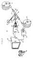
- FIG. 1 there is shown a diagramatic sketch of a near infrared light inspection arrangement 18 for optically inspecting the bulk of a natural polyethylene jacket covering a cable 20.
- the cable 20 is exposed to the inspection while it is moved from a storage reel, or cable pan, 21 to a take-up reel, or cable pan, 22.
- a halogen quartz lamp 25 shines an incident beam of light 26 onto a section of the cable.
- the cable 20 includes an opaque material 28, such as a copper tube, which will reflect any incident light beam.
- the copper provides a media for transmitting high voltage electrical power.
- a protective insulating jacket 20, which surrounds the copper, is fabricated from natural polyethylene.
- Reflected light 30 which is reflected both from the surface of the copper and from the surface of the polyethylene jacket 29, is directed to an optical polarizer 32, a magnifying lens system 33, and a long pass filter 34 to a long wavelength video camera 36.
- Signals received by the video camera 36 are retransmitted by way of a cable 38 to a high resolution video monitor 40 for producing a visible image and another cable 42 to paper copy printer 44 for making a printout of the visual image.
- a photographic copy can be made by a Polaroid Screen Shooter camera 45.
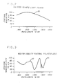
- FIG. 2 presents a graph of the operating characteristic 50 of the halogen quartz lamp, or white light source 25, shown in FIG. 1.
- the optical, or spectral, radiation of energy from the light source 25 is given as a percentage of its maximum spectral radiation for a band of wavelengths between 800 and 1600 nanometers. The maximum radiation occurs near the wavelength 1000 nanometers.
- Such a white light source is available commercially and has a much longer life and lower cost than light-emitting diodes and lasers.
- FIG. 3 presents an approximate characteristic 52 of the optical or spectral, transmissivity of a sample of a medium density natural polyethylene, Union Carbide DHDA 1184, which forms the protective insulating cable jacket 29 in FIG. 1.
- This natural polyethylene jacket 29 provides mechanical protection for the interior elements of the cable including the copper tube 28 and its contents, which are not shown. Additionally the natural polyethylene jacket 29 provides insulation for very high voltage which resides in the copper tube 28. The voltage, which may be several thousand volts, is so high that any defects in the natural polyethylene jacket 29 may cause a breakdown through the insulation and a failure of the cable system.
- transmissivity of the natural polyethylene is presented as a percentage of the maximum spectral transmissivity over the band of near infrared wavelengths between 800 and 1600 nanometers. Peaks of spectral transmissivity of the natural polyethylene occur near 1100, 1300 and 1500 nanometers.
- FIG. 4 there is presented an optical or spectral transmissivity characteristic 54 for the long pass filter 32 of FIG. 1.
- Spectral transmissivity of the filter 32 is shown as a percentage of the maximum spectral transmissivity for the band of near infrared wavelengths between 800 and 1600 nanometers.
- This filter 32 is selected to filter out visible lightwaves leaving a preponderance of near infra-red wavelengths for inspecting. It is noted that spectral transmissivity rises rapidly starting at 900 nanometers and continues rising to a knee at approximately 1100 nanometers. Thereafter it levels off for longer wavelengths up to 1600 nanometers.
- FIG. 5 presents three normalized spectral response characteristic curves 60, 62 and 64 for various infrared-sensitive electronic video camera equipments.
- the response curves are normalized for each individual video camera.
- Characteristic curve 60 shows the spectral response for a fast response CCD video movie camera which is used in an on-line manufacturing process inspection system as well as in an extrusion control system for applying a top quality polyethylene jacket 29 on the cable 20 of FIG 1. This camera will allow for rapid inspection of a long cable to identify sections which should be inspected more thoroughly.
- Characteristic curve 62 of FIG. 5 is the curve which represents a slower response video camera which is used in a static inspection station. Such a static inspection will provide a higher resolution image for those sections of cable which need a more thorough inspection.
- curve 64 is the spectral response characteristic curve for a long wavelength video camera which is used for experimental development purposes. This camera provides an even slower response time but the highest resolution image because of special features included in the camera.
- the curves 60, 62 and 64 are presented as normalized spectral responses over the band of near infrared wavelengths between 800 and 1600 nanometers.
- the optical polarizer 33 and the magnifying lens system 34 are inserted for the following optical effects.
- the optical polarizer 33 reduces the amount of reflection from the cable surface to the video camera 36 thereby enabling a clearer view of the interior of the polyethylene jacket 29.
- the magnifying lens system 34 enlarges the image and therefore enables the detection of smaller defects in the polyethylene jacket 29.
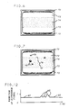
- FIG. 6 there is shown an example of the clear image of a defect free cable, as produced by the inspection system of FIG. 1.
- a dark dotted area 70 is a view of air surrounding the natural polyethylene jacket 72 of a cable.
- This area 70 of the image is dark gray because no light is reflected from the air to the camera.
- the jacket 72 is a light gray resulting from the natural polyethylene reflecting some of the incident light.
- the medium gray represents the opaque surface of a tube of copper 74 which resides in the center of the cable.
- the area of the copper 74 is a medium gray because some of the light incident on the copper is reflected. It is noted in FIG. 6 that the image is uniform in each of the areas 70, 72 and 74. On the monitor screen, those areas appear as different, but uniform shades of gray, as just described.
- FIG. 7 presents an image similar to the image of FIG. 6 except that it shows further information relating to defects. Since the light source 25 of FIG. 1 is shining on one side of the cable 20, some light is reflected from surfaces that it impinges upon. As described earlier, some wavelengths of the light source penetrate into and are transmitted through the polyethylene. Such light reflects from the surfaces of defects within the polyethylene. In FIG. 7 there are images of reflections from voids, or bubbles, 75 that are trapped in the middle of the natural polyethylene 72. Additional images of reflections are shown for other bubbles 76 trapped in the natural polyethylene between the surface of the copper tube 74 and the camera 36 of FIG. 1. Also shown in FIG.
- the inspection system can be used for statically inspecting a sample of cable or for continuously inspecting the natural polyethylene jacket of the cable as the cable passes an inspection station located along a cable fabrication line or wherever the cable is moved from one cable reel or pan to another.
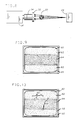
- FIG. 8 shows another inspection system, arranged in accordance with the invention.
- the cable 20, the optical polarizer 32, the magnifying lens system 33, the long pass filter 34, and the video camera 36 are positioned similarly to their positions in the arrangement of FIG. 1.
- a halogen quartz white light source 85 is positioned to shine light directly through the cable jacket to the optical polarizer 32, the magnifying lens system 33, the optical polarizer 34, and video camera 36. Because the light impinging on the video camera 36 is direct from the light source 85, that light is much brighter than the light which reaches the video camera 36 in the arrangement of FIG. 1. For the arrangement of FIG 8, special filtering or adjustments to the camera iris may be necessary.
- FIG. 9 shows the image of a defect free section of cable which results from the direct light source arrangement of FIG. 8.
- the areas of air 90 are much brighter because light is transmitted from the light source 85 directly through the air to the camera.
- Areas of natural polyethylene jacket 92 are a uniform light gray for a defect free area. The light is transmitted from the light source 85 directly through the natural polyethylene to the video camera.
- the area 94 of the copper tube is a dark gray shadow because the light from the source 85 is blocked by the opaque copper material.
- FIG. 10 there is shown a direct light view of a segment of cable with defects.
- the cable is surrounded by air 90. Since the copper is opaque, no defects on either side of the copper 94 are visible to the camera. The shadow of the copper tube obliterates the view of any such defects.
- Other defects 96 are so located in the natural polyethylene jacket 92 that they are readily detected. In such locations the appropriate wavelength light shines through the jacket to the defects and the camera. Those defects are visible in the image of FIG. 10, as produced by the camera 36 of FIG. 8.
- FIG. 11 shows a near infrared light inspection system 100 for dynamically inspecting a moving cable 105 covered by a natural polyethylene jacket. Parts of the system 100, which are similar to parts of the test arrangement 18 of FIG. 1, are given the same numerical designation.
- the cable 105 of FIG. 11 moves from left to right, it passes an optical detection station 110 having one or more light sources 25 and cameras 36. More than one light source and camera are useful for viewing all of the bulk of the natural polyethylene as it passes the detection station 110.
- Three light sources and cameras, positioned to view the cable from angles of 120 degrees from each other, can provide views of the entire bulk of the cable jacket.
- Each video camera 36 is associated with a motion detector circuit 112.
- the motion detector circuits 36 determine whether or not there are any defects in the cable jacket as the cable passes the inspection station 110. Each defect that shows in a screened image will cause a variation in the signals delivered from the relevant camera 36 to the associated motion detector circuit 112.
- FIG. 12 shows an analog representation of the magnitude of a video signal produced by one of the video cameras 36 of FIG. 11. While the video cameras are scanning any of the uniform gray parts of the cable having a defect free jacket of polyethylene and copper tube, the video signal has a uniform magnitude. Whenever a defect occurs in the natural polyethylene, the magnitude of the video signal changes, as shown by the various peaks 82. The motion detector circuits 112 detect these variations in the video signals. Leads 115 carry signals, produced by the motion detector circuits 112, whenever the polyethylene jacket contains a defect and fails inspection.
- a timer and control circuit 116 responds to the signals on the leads 115 and produces a time delayed signal representing the occurrence of any defect in the polyethylene jacket.
- the time of delay is determined by the speed of the cable and the distance between the detection station 110 and a recording inspection station 120.
- the time delayed signal from the time and control circuit 116 is timed to occur when the defective segment of cable is positioned for inspection by the recording inspection station 120.
- the optical arrangement of the light sources and cameras of the recording inspection station is similar to the detection station 110.
- the video signals representing the images of the defective segment of polyethylene jacket are transmitted by way of cables 122 through a quad combining system 124 to a video recording system 126.
- the quad combining system 124 combines signals from up to four video camera sources into four video signal windows at its output. That output is delivered to either the video recording system 126, to a video monitor (not shown) or to both.
- the video data representing the image of the defective segment of cable is recorded electronically together with the output of a visual spectrum video camera 128.
- the video camera 128 collects from a display panel 130 various information from a display panel 130. That information includes speed of the cable, location of the cable area being documented, cable identification number, etc. From the video recording, an image is produced either on a video monitor, a paper print out, or a photograph.
- the near infrared light inspection system 100 for dynamically inspecting a moving cable has some advantages over known inspection arrangements.
- the system 100 provides much clearer and more accurate inspection data than is provided by the prior art capacitance measuring system. It also provides at least as clear and accurate inspection data as that provided by the prior art far infrared inspection system. Importantly, the system 100 is much less expensive than the far infrared inspection system.
- the system 100 produces images, associated with specific locations along the cable. Those images can be evaluated either visually or, by image processing for the purpose of eliminating some cable locations for close inspection.
Landscapes
- Physics & Mathematics (AREA)
- Health & Medical Sciences (AREA)
- Life Sciences & Earth Sciences (AREA)
- Chemical & Material Sciences (AREA)
- Analytical Chemistry (AREA)
- Biochemistry (AREA)
- General Health & Medical Sciences (AREA)
- General Physics & Mathematics (AREA)
- Immunology (AREA)
- Pathology (AREA)
- Investigating Materials By The Use Of Optical Means Adapted For Particular Applications (AREA)
- Closed-Circuit Television Systems (AREA)
- Organic Insulating Materials (AREA)
Applications Claiming Priority (2)
| Application Number | Priority Date | Filing Date | Title |
|---|---|---|---|
| US283650 | 1988-12-13 | ||
| US07/283,650 US4988875A (en) | 1988-12-13 | 1988-12-13 | Near infrared polyethylene inspection system and method |
Publications (2)
| Publication Number | Publication Date |
|---|---|
| EP0373796A2 true EP0373796A2 (fr) | 1990-06-20 |
| EP0373796A3 EP0373796A3 (fr) | 1991-05-22 |
Family
ID=23087000
Family Applications (1)
| Application Number | Title | Priority Date | Filing Date |
|---|---|---|---|
| EP19890312503 Withdrawn EP0373796A3 (fr) | 1988-12-13 | 1989-11-30 | Système et méthode d'inspection de polyéthylène par infrarouge proche |
Country Status (6)
| Country | Link |
|---|---|
| US (1) | US4988875A (fr) |
| EP (1) | EP0373796A3 (fr) |
| JP (1) | JPH0692942B2 (fr) |
| KR (1) | KR960003194B1 (fr) |
| AU (1) | AU613253B2 (fr) |
| CA (1) | CA2001666C (fr) |
Cited By (6)
| Publication number | Priority date | Publication date | Assignee | Title |
|---|---|---|---|---|
| US5256886A (en) * | 1991-04-30 | 1993-10-26 | E. I. Du Pont De Nemours And Company | Apparatus for optically detecting contamination in particles of low optical-loss material |
| FR2696006A1 (fr) * | 1992-09-21 | 1994-03-25 | Alcatel Cable | Dispositif de contrôle de qualité d'un gainage du type polyéthylène. |
| EP0902275A1 (fr) * | 1997-09-12 | 1999-03-17 | Philip Morris Products Inc. | Dispositif de contrÔle des rabats d'une feuille d'emballage transparente |
| DE19955135A1 (de) * | 1999-11-17 | 2001-05-31 | Der Gruene Punkt Duales Syst | Verfahren und Vorrichtung zum Bestimmen der Materialsorte eines Kunststoffes |
| EP1071944A4 (fr) * | 1998-04-17 | 2003-01-02 | Crc For Intelligent Mfg System | Appareil pour detecter des defauts |
| WO2021140259A1 (fr) | 2020-01-11 | 2021-07-15 | Quandum Aerospace S.L. | Système de positionnement de chambres et de lumières pour l'inspection de tuyaux utilisés dans le ravitaillement aérien et procédé d'inspection |
Families Citing this family (31)
| Publication number | Priority date | Publication date | Assignee | Title |
|---|---|---|---|---|
| IT1240980B (it) * | 1990-09-10 | 1993-12-27 | Sip | Apparecchiatura per la misura e il controllo dell'eccentricita' dello strato di rivestimento colorato di fibre ottiche. |
| US5241184A (en) * | 1991-09-26 | 1993-08-31 | Electric Power Research Institute | Apparatus and method for quantizing remaining lifetime of transmission cable insulation |
| US5345081A (en) * | 1992-09-10 | 1994-09-06 | Penetect, Inc. | Pit detector and method |
| US5383135A (en) * | 1992-12-31 | 1995-01-17 | Zellweger Uster, Inc. | Acquisition, measurement and control of thin webs on in-process textile materials |
| US5444265A (en) * | 1993-02-23 | 1995-08-22 | Lsi Logic Corporation | Method and apparatus for detecting defective semiconductor wafers during fabrication thereof |
| DE19507643C1 (de) * | 1995-03-04 | 1996-07-25 | Rockwool Mineralwolle | Verfahren zum Unschädlichmachen von in einem Mineralwollevlies befindlichen heißen Einschlüssen und Vorrichtung zur Durchführung des Verfahrens |
| US5943126A (en) * | 1997-03-11 | 1999-08-24 | Lucent Technologies Inc. | Method and apparatus for detecting surface qualities on an optical fiber |
| US5880825A (en) * | 1997-03-11 | 1999-03-09 | Lucent Technologies Inc. | Method and apparatus for detecting defects in an optical fiber |
| US6661502B1 (en) | 1999-10-28 | 2003-12-09 | Fitel Usa Corp. | Method and apparatus for measuring the diameter and/or eccentricity of a coating layer of a coated optical fiber |
| US20020033943A1 (en) * | 2000-09-19 | 2002-03-21 | Horst Clauberg | Device and method for the optical inspection, assessment, and control of colored plastic articles and/or container contents |
| US20030118230A1 (en) * | 2001-12-22 | 2003-06-26 | Haoshi Song | Coiled tubing inspection system using image pattern recognition |
| US6677591B1 (en) | 2002-01-30 | 2004-01-13 | Ciena Corporation | Method and system for inspecting optical devices |
| ATE538373T1 (de) * | 2002-03-06 | 2012-01-15 | Polymer Aging Concepts Inc | Elektrisches überwachungsverfahren für polymere |
| US20040026622A1 (en) * | 2002-08-06 | 2004-02-12 | Dimarzio Don | System and method for imaging of coated substrates |
| US7462809B2 (en) * | 2004-10-22 | 2008-12-09 | Northrop Grumman Corporation | Spectral filter system for infrared imaging of substrates through coatings |
| US7164146B2 (en) * | 2004-10-22 | 2007-01-16 | Northrop Grumman Corporation | System for detecting structural defects and features utilizing blackbody self-illumination |
| US20080111074A1 (en) * | 2004-10-22 | 2008-05-15 | Northrop Grumman Corporation | Method for infrared imaging of substrates through coatings |
| US20060244948A1 (en) * | 2005-04-12 | 2006-11-02 | Overbeck James L | Systems and methods for validating a security feature of an object |
| EP1879019B1 (fr) * | 2005-04-21 | 2015-02-25 | Sumitomo Electric Industries, Ltd. | Dispositif d'inspection de fil supraconducteur |
| US8766192B2 (en) * | 2010-11-01 | 2014-07-01 | Asm Assembly Automation Ltd | Method for inspecting a photovoltaic substrate |
| US9665932B2 (en) * | 2013-09-03 | 2017-05-30 | Thales Transport & Security, Inc. | Camera based cable inspection system |
| US9828846B2 (en) * | 2014-07-31 | 2017-11-28 | Halliburton Energy Services, Inc. | Self-diagnosing composite slickline cables |
| US11333613B2 (en) * | 2015-04-07 | 2022-05-17 | The Boeing Company | Apparatus and methods of inspecting a wire segment |
| FI129412B (en) * | 2018-04-13 | 2022-01-31 | Maillefer Sa | An arrangement and a method for surface defect detection of a cable |
| CN112557438B (zh) * | 2020-11-11 | 2022-05-20 | 南方电网科学研究院有限责任公司 | 一种高压交流电缆绝缘用预交联料存储寿命检测方法 |
| US12379717B2 (en) * | 2022-08-03 | 2025-08-05 | Industrial Video Solutions Inc. | Systems and methods for monitoring and controlling industrial processes |
| US12198438B2 (en) * | 2022-08-03 | 2025-01-14 | Industrial Video Solutions Inc. | Systems and methods for monitoring and controlling industrial processes |
| US12169400B2 (en) | 2022-08-03 | 2024-12-17 | Industrial Video Solutions Inc. | Systems and methods for monitoring and controlling industrial processes |
| US12130249B2 (en) | 2022-08-03 | 2024-10-29 | Industrial Video Solutions Inc. | Systems and methods for monitoring and controlling industrial processes |
| EP4563965A1 (fr) * | 2023-11-29 | 2025-06-04 | Nexans | Procédé de contrôle de qualité pour spécimen de câble |
| WO2025215745A1 (fr) * | 2024-04-09 | 2025-10-16 | 住友電気工業株式会社 | Câble d'alimentation, procédé de fabrication de câble d'alimentation et procédé d'inspection de câble d'alimentation |
Family Cites Families (9)
| Publication number | Priority date | Publication date | Assignee | Title |
|---|---|---|---|---|
| CH452229A (de) * | 1965-06-18 | 1968-05-31 | Siemens Ag | Kabelprüfverfahren |
| US3870884A (en) * | 1973-08-24 | 1975-03-11 | Infra Systems Inc | Apparatus for negating effect of scattered signals upon accuracy of dual-beam infrared measurements |
| US4139306A (en) * | 1977-02-07 | 1979-02-13 | General Electric Company | Television inspection system |
| US4208126A (en) * | 1978-05-24 | 1980-06-17 | Electric Power Research Institute, Inc. | System for detecting foreign particles or voids in electrical cable insulation and method |
| US4302108A (en) * | 1979-01-29 | 1981-11-24 | Polaroid Corporation | Detection of subsurface defects by reflection interference |
| US4363966A (en) * | 1980-09-22 | 1982-12-14 | Electric Power Research Institute, Inc. | Detection system for distinguishing between voids and foreign particles in materials and method |
| CH653459A5 (de) * | 1981-04-16 | 1985-12-31 | Landis & Gyr Ag | Dokument mit einem sicherheitsfaden und verfahren zur echtheitspruefung desselben. |
| US4692799A (en) * | 1982-04-05 | 1987-09-08 | Showa Electric Wire & Cable Co., Ltd. | Automatic inspection system for detecting foreign matter |
| US4764681A (en) * | 1987-06-04 | 1988-08-16 | Owens-Illinois Televison Products Inc. | Method of and apparatus for electrooptical inspection of articles |
-
1988
- 1988-12-13 US US07/283,650 patent/US4988875A/en not_active Expired - Lifetime
-
1989
- 1989-10-27 CA CA002001666A patent/CA2001666C/fr not_active Expired - Lifetime
- 1989-11-30 EP EP19890312503 patent/EP0373796A3/fr not_active Withdrawn
- 1989-12-04 AU AU45859/89A patent/AU613253B2/en not_active Ceased
- 1989-12-11 KR KR1019890018267A patent/KR960003194B1/ko not_active Expired - Fee Related
- 1989-12-11 JP JP1321242A patent/JPH0692942B2/ja not_active Expired - Fee Related
Cited By (9)
| Publication number | Priority date | Publication date | Assignee | Title |
|---|---|---|---|---|
| US5256886A (en) * | 1991-04-30 | 1993-10-26 | E. I. Du Pont De Nemours And Company | Apparatus for optically detecting contamination in particles of low optical-loss material |
| FR2696006A1 (fr) * | 1992-09-21 | 1994-03-25 | Alcatel Cable | Dispositif de contrôle de qualité d'un gainage du type polyéthylène. |
| EP0589769A1 (fr) * | 1992-09-21 | 1994-03-30 | Alcatel Cable | Dispositif de contrôle de qualité d'un gainage du type polyéthylène |
| EP0902275A1 (fr) * | 1997-09-12 | 1999-03-17 | Philip Morris Products Inc. | Dispositif de contrÔle des rabats d'une feuille d'emballage transparente |
| EP1071944A4 (fr) * | 1998-04-17 | 2003-01-02 | Crc For Intelligent Mfg System | Appareil pour detecter des defauts |
| US6597455B1 (en) | 1998-04-17 | 2003-07-22 | Crc For Intelligent Manufacturing Systems And Technologies Ltd. | Fault detection apparatus |
| DE19955135A1 (de) * | 1999-11-17 | 2001-05-31 | Der Gruene Punkt Duales Syst | Verfahren und Vorrichtung zum Bestimmen der Materialsorte eines Kunststoffes |
| DE19955135C2 (de) * | 1999-11-17 | 2001-10-18 | Der Gruene Punkt Duales Syst | Vorrichtung zum Bestimmen der Materialsorte bei Folien aus Kunststoff als Bestandteil einer Wertstoffsortieranlage |
| WO2021140259A1 (fr) | 2020-01-11 | 2021-07-15 | Quandum Aerospace S.L. | Système de positionnement de chambres et de lumières pour l'inspection de tuyaux utilisés dans le ravitaillement aérien et procédé d'inspection |
Also Published As
| Publication number | Publication date |
|---|---|
| CA2001666A1 (fr) | 1990-06-13 |
| JPH02223849A (ja) | 1990-09-06 |
| JPH0692942B2 (ja) | 1994-11-16 |
| KR960003194B1 (ko) | 1996-03-06 |
| US4988875A (en) | 1991-01-29 |
| KR900010384A (ko) | 1990-07-07 |
| EP0373796A3 (fr) | 1991-05-22 |
| CA2001666C (fr) | 1994-12-13 |
| AU613253B2 (en) | 1991-07-25 |
| AU4585989A (en) | 1990-07-05 |
Similar Documents
| Publication | Publication Date | Title |
|---|---|---|
| US4988875A (en) | Near infrared polyethylene inspection system and method | |
| US4223346A (en) | Automatic defect detecting inspection apparatus | |
| CA1217951A (fr) | Appareil et methode pour l'analyse du circuit de polymere fondu | |
| US4301409A (en) | Solar cell anomaly detection method and apparatus | |
| US5355213A (en) | Inspection system for detecting surface flaws | |
| US6011620A (en) | Method and apparatus for the automatic inspection of optically transmissive planar objects | |
| KR0167363B1 (ko) | 용융수지내의 불순물 탐지법 | |
| US4401893A (en) | Method and apparatus for optically inspecting a moving web of glass | |
| US5274243A (en) | Cylindrical allumination system for inspection of sheet material | |
| US4448527A (en) | Method and apparatus for detecting surface defects in mechanical workpieces | |
| EP1301771B1 (fr) | Determination de types de fibres optiques | |
| JPH0249194B2 (fr) | ||
| US5606410A (en) | Method for controlling the surface state of one face of a solid and the associated device | |
| GB2095398A (en) | Detecting surface defects in workpieces | |
| US5880825A (en) | Method and apparatus for detecting defects in an optical fiber | |
| JPH10260027A (ja) | 絶縁テープの異物検出・除去装置 | |
| US7420146B1 (en) | Laser beam monitor and control method | |
| GB2185813A (en) | Assessing soldered joints | |
| JPH11271175A (ja) | 被覆層で包囲された光ファイバ内の欠陥検出装置及び方法 | |
| EP0051899A1 (fr) | Dispositif pour la détection et l'évaluation automatiques des caractéristiques de documents imprimés | |
| JPH09304412A (ja) | 透明流体中の異物検出装置 | |
| JP2906745B2 (ja) | 表面うねり検査装置 | |
| JPH0611457A (ja) | フィルム中の異物検出方法及びその装置 | |
| JPH09304413A (ja) | 透明流体中の異物検出方法と装置 | |
| JPH01214743A (ja) | 光学検査装置 |
Legal Events
| Date | Code | Title | Description |
|---|---|---|---|
| PUAI | Public reference made under article 153(3) epc to a published international application that has entered the european phase |
Free format text: ORIGINAL CODE: 0009012 |
|
| AK | Designated contracting states |
Kind code of ref document: A2 Designated state(s): DE FR GB IT |
|
| PUAL | Search report despatched |
Free format text: ORIGINAL CODE: 0009013 |
|
| AK | Designated contracting states |
Kind code of ref document: A3 Designated state(s): DE FR GB IT |
|
| 17P | Request for examination filed |
Effective date: 19911030 |
|
| 17Q | First examination report despatched |
Effective date: 19931008 |
|
| RAP3 | Party data changed (applicant data changed or rights of an application transferred) |
Owner name: AT&T CORP. |
|
| STAA | Information on the status of an ep patent application or granted ep patent |
Free format text: STATUS: THE APPLICATION IS DEEMED TO BE WITHDRAWN |
|
| 18D | Application deemed to be withdrawn |
Effective date: 19960508 |