EP0377165A2 - Dispositif de commande de gain - Google Patents
Dispositif de commande de gain Download PDFInfo
- Publication number
- EP0377165A2 EP0377165A2 EP89123487A EP89123487A EP0377165A2 EP 0377165 A2 EP0377165 A2 EP 0377165A2 EP 89123487 A EP89123487 A EP 89123487A EP 89123487 A EP89123487 A EP 89123487A EP 0377165 A2 EP0377165 A2 EP 0377165A2
- Authority
- EP
- European Patent Office
- Prior art keywords
- controller
- tone
- electronic volume
- gain
- frequency characteristic
- Prior art date
- Legal status (The legal status is an assumption and is not a legal conclusion. Google has not performed a legal analysis and makes no representation as to the accuracy of the status listed.)
- Granted
Links
Images




Classifications
-
- H—ELECTRICITY
- H03—ELECTRONIC CIRCUITRY
- H03G—CONTROL OF AMPLIFICATION
- H03G5/00—Tone control or bandwidth control in amplifiers
- H03G5/02—Manually-operated control
-
- H—ELECTRICITY
- H03—ELECTRONIC CIRCUITRY
- H03G—CONTROL OF AMPLIFICATION
- H03G9/00—Combinations of two or more types of control, e.g. gain control and tone control
- H03G9/02—Combinations of two or more types of control, e.g. gain control and tone control in untuned amplifiers
Definitions
- the present invention relates to a gain controller for use in an apparatus comprising a frequency characteristic controller (hereinafter called tone controller) and, more particularly, to a gain controller of the type capable of controlling a gain in the apparatus by maintaining a good S/N ratio and preventing a clipping distortion from causing upon saturation in the tone controller.
- tone controller a frequency characteristic controller
- an electronic volume control circuit has been used in an audio equipment such, for example, as it is shown in the disclosure of Japanese Laid-open Utility Model Application No. 63-92418 hereby incorporated as the prior art by reference.
- a first depression detection signal is fed to a control circuit when a first push button switch is depressed for controlling the electronic volume controller to increase a resistance value thereof and a second depression detection signal is fed to the control circuit when a second push button switch is depressed for controlling the electronic volume controller to decrease a resistance value thereof, thereby if the first and the second depression detection signals are fed simultaneously to the control circuit, the electronic volume controller is so adjusted as to be set to a certain amount of value under the control of the control circuit.
- Japanese Utility Model Publication No. 63-111015 is incorporated as the prior art tone control device for audio equipments by reference.
- a tone characteristic for a reproduced sound is set by a tone quality setting unit and the selected tone qualities for respective sound sources are stored in a memory unit, the tone quality of an audio signal selected one out of several sound sources is controlled on the basis of the corresponding tone characteristic thereto by means of a tone controller, and the tone characteristic that corresponds to the selected sound source is read from the memory unit when the reproduction of the selected sound source is started and fed to the tone controller by means of a control unit.
- FIG. 1 shows a schematic diagram of an audio equipment comprising the prior art tone controller, wherein numeral 1 denotes a tone controller, numeral 6 denotes a fixed attenuator made up of fixed resistors and numeral 7 denotes a volume controller made up of a variable resistor.
- the tone controller 1 is provided for changing a frequency characteristic by setting a gain and an attenuation against a specific frequency band, thereby a frequency spectrum of an audio signal can be varied.
- the volume controller 7 is provided for attenuating the audio signal uniformly across the whole band by a discretionary amount of level.
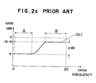
- the level of an output signal "ii" of the fixed attenuator 6 is attenuated by an amount of "b" dB in the whole frequency band as it is shown in FIG. 2b. Accordingly, there needed is the setting of the maximum input level in advance against the tone controller 1 in consideration of the maximum boosting (the maximum gain) value thereof.
- the amount of margin "b" dB is so selected as to be such a value within which a voice signal is not clipped even at the maximum boosting in the tone controller 1. Then an output boosted by the amount of "a" dB at the higher frequency band B is attained from the tone controller 1 as it is shown in FIG. 2c.
- the margin provided for the tone controller will be of no use if there is no boosting in the tone controller and resulting in the attenuation of the audio signal level less than required signal level. This, in turn, aggravates the S/N rat io and deteriorates the quality of the audio signal.
- a gain controller in accordance with the present invention comprises a first electronic volume controller provided at the front stage of a tone controller, a second electronic volume controller provided at the rare stage of the tone controller and a microprocessor for controlling the first electronic volume controller, the second electronic volume controller and the tone con troller in a cooperative manner.
- the microprocessor in the gain controller provides the controls in such a manner as to attenuate an input signal at the first electronic volume controller by a required amount that corresponds to the amount of gain (boosting), which is needed for executing the selected frequency characteristic, in the tone controller before applying thereto and to make an amount of attenuation at the second electronic volume controller to conform to the difference between the whole attenuation of the equipment and the amount of attenuation given at the first electronic volume controller.
- FIG. 3 there is shown an embodiment of this invention in a block diagram, wherein numeral 1 denotes a tone controller to be used as a frequency characteristic controller, numeral 2 denotes a first electronic volume controller to be used as an attenuator and is provided at the front stage of the tone controller 1, numeral 3 denotes a second electronic volume controller to be used another attenuator and is provided at the rare stage of the tone controller 1 and numeral 4 denotes a microprocessor.
- numeral 1 denotes a tone controller to be used as a frequency characteristic controller
- numeral 2 denotes a first electronic volume controller to be used as an attenuator and is provided at the front stage of the tone controller
- numeral 3 denotes a second electronic volume controller to be used another attenuator and is provided at the rare stage of the tone controller 1
- numeral 4 denotes a microprocessor.
- the tone controller 1, the first electronic volume controller 2 and the second electronic volume controller 3 are operated in a cooperative manner under the control of the microprocessor 4. More specifically, an amount of attenuation of the first electronic volume controller 2 and that of the second electronic volume controller 3 are determined by the microprocessor 4 in response to the frequency characteristic which has been set in the tone controller 1.
- the first electronic volume controller 2, the second electronic volume controller 3 and the microprocessor 4 constitute the gain controller 5 of the present invention.
- the frequency characteristics at the various points of the gain controller are illustrated in FIG. 6a - 6c provided that the frequency characteristic of the tone controller 1 is so selected as to have "a" dB gain within a higher frequency band B as it is shown in FIG. 4 and the total attenuation of the gain controller 5 or the sum of the attenuation 5 of the first and second electronic volume controllers 2, 3 is so selected as to be "c" dB within the whole frequency band as it is shown in FIG. 5.
- (i) - (iv) denote audio signals in-between the blocks of FIG. 3.
- the shown frequency characteristic illustrates the input signal level of 0 dB of the first electronic volume controller 2. This is an allowable signal level for the tone controller 1 not to cause clipping distortions at when the frequency charac teristic thereof is set to zero in the amount of boosting or no amplification therein.
- the microprocessor 4 controls the first electronic volume controller 2 to attenuate the input signal (i) by the amount of "a" dB within the whole frequency band since the frequency characteristic of the tone controller has been set to that shown in FIG. 4.
- the attenuated input signal is shown by (ii) in FIG. 6b. Therefore, the gain frequency characteristic for the signal at the output point of the tone controller 1 is shown by (iii) in FIG. 6b and 6c and the maximum level does never exceed 0 dB.
- the signal will exceeds the 0 dB level at the maximum level thereof in the tone controller as it is shown by (iiia) in FIG. 6b and this will result in the clipping distortion to be encountered in the tone controller 1.
- the microprocessor 4 then controls the second electronic volume controller 3 to attenuate the signal by an amount of "c - a" dB, which is the difference between the total attenuation "c" dB of the gain controller 5 and the attenuation "a” dB at the first volume controller 2 as they are shown in FIG. 6c, for providing the final gain frequency characteristic shown by (iv) in FIG. 6c.
- FIG. 7 A state of gain variation for the audio signal along each block of the gain controller is shown in FIG. 7, whereby the frequency characteristic of the tone controller 1 is set as it is shown in FIG. 4. More specifically, it is assumed that the input signal (i) to the first electronic volume controller 2 has the maximum allowable level of 0 dB for the tone controller 1. The first electronic volume controller 2 is then controlled by the microprocessor 4 in accordance with a control signal 1 for attenuating the input signal by an amount of a dB which equals to the amount of boosting for attaining the selected frequency characteristic in the tone controller 1.
- the signal is amplified by the amount of "a" dB within the frequency band B in the tone controller 1 in accordance with a control signal II fed by the microprocessor 4 without causing any level change in the frequency band A.
- the microprocessor also generates a control signal III simultaneously with the control signal I for the second electronic volume controller 3 and thereby controls the attenuation in the second electronic volume controller 3 to attenuate the signal by the amount of "c - a" dB which is given by subtracting "a” dB or the attenuation in the first electronic volume controller 2 from "c" dB or the total attenuation of the gain controller 5.
- the output signal (iv) of the second electronic volume controller 3 is equivalent to the input signal (i) attenuated by the amount of "c" dB in the frequency band A and "c - a" dB in the frequency band B.
- the gain controller in accordance with this invention is significant in respect of the S/N ratio as it will be kept preferable.
- the total attenuation of the gain controller 5 has been considered to be larger than the gain attained in either frequency band of the tone controller, however, if the total attenuation of the gain controller is less than the gain to be attained in the tone controller, an amount of attenuation at the first electronic volume controller 2 should be limited not to exceed the amount of attenuation being set for the whole system provided that the attenuation at the second electronic volume controller 3 is 0 db.
- the invention has been described with reference to the preferred embodiment wherein the signal in the certain frequency band is amplified in the tone controller 1, however, in case of attenuating the signal in the tone controller, the attenuation at the first electronic volume controller 2 will be ceased under the control of the microprocessor 4.
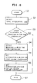
- the microprocessor initiate the operation with a first step S1 wherein the whole system is initially set to have a predetermined amount of attenuation with an input device such as a switch (not shown) and the power source is turned ON.
- the set value "c" dB for the attenuation of the whole system is detected by the microprocessor 4 at step S2 from the status of the input device such as the switch. It is then determined by the microprocessor 4 at step S3 whether or not an amount of boosting has been set in the tone controller 1 from the status of another input device such as a switch and the like (not shown).
- step S4 If it has, the amount of boosting "a" dB is detected at step S4. Whereas if it has not, the program goes directly to step 7.
- An amount of attenuation of the first electronic volume controller 2 is determined at step S5 on the basis of the detected value "a" dB and the control of the microprocessor 4.
- tone controller 1 is used for the frequency characteristic controller. It will, however, be apparent that many modification may be made, for example, a graphic equalizer, which is one of the frequency characteristic compensators, that can control a gain independently for a plurality of frequencies may be substituted for the tone controller.
- the attenuation of a signal level should be kept as small as possible and the upper limit of the signal level should be kept within the maximum value to be afforded. Accordingly, it is needless to say that the same advantages heretofore described can also be attained by an preferred embodiment of this invention even in the digital signal processing.
- the present invention provides an improved gain controller for minimizing the attenuation for an input signal and preventing the deterioration of S/N ratio as well as the occurrence of clipping distortion at the frequency characteristic control stage.
Landscapes
- Tone Control, Compression And Expansion, Limiting Amplitude (AREA)
- Control Of Amplification And Gain Control (AREA)
Applications Claiming Priority (2)
| Application Number | Priority Date | Filing Date | Title |
|---|---|---|---|
| JP1001505A JP2827240B2 (ja) | 1989-01-06 | 1989-01-06 | ゲイン調節器 |
| JP1505/89 | 1989-01-06 |
Publications (3)
| Publication Number | Publication Date |
|---|---|
| EP0377165A2 true EP0377165A2 (fr) | 1990-07-11 |
| EP0377165A3 EP0377165A3 (en) | 1990-12-19 |
| EP0377165B1 EP0377165B1 (fr) | 1994-08-24 |
Family
ID=11503334
Family Applications (1)
| Application Number | Title | Priority Date | Filing Date |
|---|---|---|---|
| EP89123487A Expired - Lifetime EP0377165B1 (fr) | 1989-01-06 | 1989-12-19 | Dispositif de commande de gain |
Country Status (7)
| Country | Link |
|---|---|
| US (1) | US5127058A (fr) |
| EP (1) | EP0377165B1 (fr) |
| JP (1) | JP2827240B2 (fr) |
| KR (1) | KR930001295B1 (fr) |
| AU (1) | AU624206B2 (fr) |
| CA (1) | CA2006288C (fr) |
| DE (1) | DE68917710T2 (fr) |
Cited By (5)
| Publication number | Priority date | Publication date | Assignee | Title |
|---|---|---|---|---|
| GB2239360B (en) * | 1989-12-19 | 1994-08-31 | Pioneer Electronic Corp | Audio reproduction system |
| EP0616425A1 (fr) * | 1993-03-19 | 1994-09-21 | Koninklijke Philips Electronics N.V. | Montage amplificateur audio |
| EP1622418A1 (fr) * | 2004-07-22 | 2006-02-01 | Jazz Hipster Corporation | Systeme numerique pour optimisation de la frequence audio |
| WO2008010029A1 (fr) * | 2006-07-17 | 2008-01-24 | Sony Ericsson Mobile Communications Ab | Profil de gain audiofréquence fonction du volume |
| EP2128978A1 (fr) * | 2008-05-30 | 2009-12-02 | Sony Corporation | Appareil et procédé de reproduction |
Families Citing this family (10)
| Publication number | Priority date | Publication date | Assignee | Title |
|---|---|---|---|---|
| DE4303386A1 (de) * | 1993-02-05 | 1994-08-11 | Blaupunkt Werke Gmbh | Schaltungsanordnung zur digitalen Verarbeitung von Audiosignalen |
| JP3097407B2 (ja) * | 1993-08-18 | 2000-10-10 | 松下電器産業株式会社 | 音響再生装置の音量、音質調整回路 |
| DE19630330C2 (de) * | 1996-07-26 | 1998-11-19 | Sgs Thomson Microelectronics | Audiosignalprozessor |
| KR100230102B1 (ko) * | 1996-12-11 | 1999-11-15 | 구자홍 | 볼륨레벨에 따른 음성조정방법 |
| JP4016206B2 (ja) | 2003-11-28 | 2007-12-05 | ソニー株式会社 | 音声信号処理装置及び音声信号処理方法 |
| DE102004055738B4 (de) * | 2004-11-18 | 2010-11-04 | Fachhochschule Jena | Signalbearbeitungseinheit und Signalbearbeitungsverfahren |
| JP2009260682A (ja) * | 2008-04-17 | 2009-11-05 | Kenwood Corp | オーディオ装置 |
| EP2392072A4 (fr) * | 2009-02-02 | 2014-09-03 | Hewlett Packard Development Co | Procédé de nivellement d'une pluralité de signaux audio |
| JP5240039B2 (ja) * | 2009-04-20 | 2013-07-17 | 株式会社Jvcケンウッド | 周波数特性調整装置、プログラム、及び周波数特性調整方法 |
| JP5196208B2 (ja) * | 2011-09-05 | 2013-05-15 | オンキヨー株式会社 | 音量調整装置 |
Family Cites Families (14)
| Publication number | Priority date | Publication date | Assignee | Title |
|---|---|---|---|---|
| BE646245A (fr) * | 1963-04-08 | |||
| JPS5087855U (fr) * | 1973-12-13 | 1975-07-25 | ||
| US4396806B2 (en) * | 1980-10-20 | 1998-06-02 | A & L Ventures I | Hearing aid amplifier |
| FR2501935B1 (fr) * | 1981-03-13 | 1985-09-13 | Thomson Csf | Circuit de commande de volume et de tonalite incorporant une correction physiologique sans filtre supplementaire |
| US4406923A (en) * | 1981-10-28 | 1983-09-27 | Cbs Inc. | Automatic loudness controller |
| JPH0240814B2 (ja) * | 1982-09-03 | 1990-09-13 | Yamaide Kosan Kk | Kenchikuyobosuikoho |
| JP2681349B2 (ja) * | 1986-08-08 | 1997-11-26 | ヤマハ株式会社 | スピーカ再生装置 |
| JPS6392418A (ja) * | 1986-10-08 | 1988-04-22 | Toyo Tire & Rubber Co Ltd | タイヤ及びその製造方法 |
| JPS63111015A (ja) * | 1986-10-29 | 1988-05-16 | Toyoda Gosei Co Ltd | 一定量供給噴射装置 |
| JPH07105680B2 (ja) * | 1986-12-24 | 1995-11-13 | 富士通テン株式会社 | 音量調整回路 |
| JPS63309011A (ja) * | 1987-06-11 | 1988-12-16 | Matsushita Electric Ind Co Ltd | ディジィタル・グラフィック・イコライザ |
| JP2517000B2 (ja) * | 1987-09-17 | 1996-07-24 | 松下電器産業株式会社 | ポ―タブル情報機器 |
| JPH0691394B2 (ja) * | 1988-03-11 | 1994-11-14 | パイオニア株式会社 | 出力レベル制御装置 |
| US4885792A (en) * | 1988-10-27 | 1989-12-05 | The Grass Valley Group, Inc. | Audio mixer architecture using virtual gain control and switching |
-
1989
- 1989-01-06 JP JP1001505A patent/JP2827240B2/ja not_active Expired - Fee Related
- 1989-12-19 DE DE68917710T patent/DE68917710T2/de not_active Expired - Fee Related
- 1989-12-19 EP EP89123487A patent/EP0377165B1/fr not_active Expired - Lifetime
- 1989-12-20 AU AU47193/89A patent/AU624206B2/en not_active Ceased
- 1989-12-20 US US07/454,030 patent/US5127058A/en not_active Expired - Lifetime
- 1989-12-21 CA CA002006288A patent/CA2006288C/fr not_active Expired - Fee Related
- 1989-12-28 KR KR1019890019832A patent/KR930001295B1/ko not_active Expired - Fee Related
Cited By (6)
| Publication number | Priority date | Publication date | Assignee | Title |
|---|---|---|---|---|
| GB2239360B (en) * | 1989-12-19 | 1994-08-31 | Pioneer Electronic Corp | Audio reproduction system |
| EP0616425A1 (fr) * | 1993-03-19 | 1994-09-21 | Koninklijke Philips Electronics N.V. | Montage amplificateur audio |
| EP1622418A1 (fr) * | 2004-07-22 | 2006-02-01 | Jazz Hipster Corporation | Systeme numerique pour optimisation de la frequence audio |
| WO2008010029A1 (fr) * | 2006-07-17 | 2008-01-24 | Sony Ericsson Mobile Communications Ab | Profil de gain audiofréquence fonction du volume |
| EP2128978A1 (fr) * | 2008-05-30 | 2009-12-02 | Sony Corporation | Appareil et procédé de reproduction |
| US8737644B2 (en) | 2008-05-30 | 2014-05-27 | Sony Corporation | Reproducing apparatus and reproducing method |
Also Published As
| Publication number | Publication date |
|---|---|
| CA2006288A1 (fr) | 1990-07-06 |
| AU624206B2 (en) | 1992-06-04 |
| AU4719389A (en) | 1990-07-12 |
| US5127058A (en) | 1992-06-30 |
| KR930001295B1 (ko) | 1993-02-25 |
| JP2827240B2 (ja) | 1998-11-25 |
| DE68917710T2 (de) | 1994-12-15 |
| JPH02181507A (ja) | 1990-07-16 |
| EP0377165B1 (fr) | 1994-08-24 |
| EP0377165A3 (en) | 1990-12-19 |
| KR900012421A (ko) | 1990-08-04 |
| CA2006288C (fr) | 1993-07-20 |
| DE68917710D1 (de) | 1994-09-29 |
Similar Documents
| Publication | Publication Date | Title |
|---|---|---|
| EP0377165A2 (fr) | Dispositif de commande de gain | |
| KR101106031B1 (ko) | 하이브리드 디지털/아날로그 음향 세기―보상 볼륨 제어 장치 및 그 제어 방법 | |
| US5844992A (en) | Fuzzy logic device for automatic sound control | |
| JPH01231510A (ja) | 出力レベル制御装置 | |
| US20010007590A1 (en) | Loudness volume control system | |
| US7460678B2 (en) | Digital audio processor | |
| US7110557B2 (en) | Level adjustment circuit | |
| EP0944166B1 (fr) | Circuit de commande automatique de dynamique | |
| RU2239278C1 (ru) | Психоакустический процессор (адаптивный эквалайзер) | |
| US3548334A (en) | Noise reduction circuit and system | |
| US4392114A (en) | Audio device having a tone control cancelling circuit | |
| JPH10313224A (ja) | 音響装置および音響装置における音量調整方法 | |
| JPH06232662A (ja) | 音量制御装置 | |
| JPH1131934A (ja) | 音声信号処理装置 | |
| JP3247526B2 (ja) | オーディオ信号のレベル調整装置 | |
| JP3067409B2 (ja) | ハウリング防止プロセッサ | |
| JPH07105680B2 (ja) | 音量調整回路 | |
| KR100197612B1 (ko) | 음량제한장치 | |
| JP2540558B2 (ja) | 音響装置 | |
| JPH01206712A (ja) | オーディオ装置 | |
| JP2737542B2 (ja) | レベル制御増幅器 | |
| JPS59189709A (ja) | 電子ボリユ−ム回路 | |
| JPS6110304A (ja) | 歪防止回路 | |
| KR19990003387A (ko) | 팝노이즈 제거장치 및 방법 | |
| JPS6247003B2 (fr) |
Legal Events
| Date | Code | Title | Description |
|---|---|---|---|
| PUAI | Public reference made under article 153(3) epc to a published international application that has entered the european phase |
Free format text: ORIGINAL CODE: 0009012 |
|
| AK | Designated contracting states |
Kind code of ref document: A2 Designated state(s): DE FR GB NL |
|
| PUAL | Search report despatched |
Free format text: ORIGINAL CODE: 0009013 |
|
| AK | Designated contracting states |
Kind code of ref document: A3 Designated state(s): DE FR GB NL |
|
| 17P | Request for examination filed |
Effective date: 19901219 |
|
| 17Q | First examination report despatched |
Effective date: 19930513 |
|
| GRAA | (expected) grant |
Free format text: ORIGINAL CODE: 0009210 |
|
| AK | Designated contracting states |
Kind code of ref document: B1 Designated state(s): DE FR GB NL |
|
| REF | Corresponds to: |
Ref document number: 68917710 Country of ref document: DE Date of ref document: 19940929 |
|
| ET | Fr: translation filed | ||
| PLBE | No opposition filed within time limit |
Free format text: ORIGINAL CODE: 0009261 |
|
| STAA | Information on the status of an ep patent application or granted ep patent |
Free format text: STATUS: NO OPPOSITION FILED WITHIN TIME LIMIT |
|
| 26N | No opposition filed | ||
| REG | Reference to a national code |
Ref country code: GB Ref legal event code: 746 Effective date: 19951106 |
|
| REG | Reference to a national code |
Ref country code: FR Ref legal event code: D6 |
|
| PGFP | Annual fee paid to national office [announced via postgrant information from national office to epo] |
Ref country code: FR Payment date: 19981209 Year of fee payment: 10 |
|
| PGFP | Annual fee paid to national office [announced via postgrant information from national office to epo] |
Ref country code: GB Payment date: 19981224 Year of fee payment: 10 |
|
| PGFP | Annual fee paid to national office [announced via postgrant information from national office to epo] |
Ref country code: NL Payment date: 19981229 Year of fee payment: 10 Ref country code: DE Payment date: 19981229 Year of fee payment: 10 |
|
| PG25 | Lapsed in a contracting state [announced via postgrant information from national office to epo] |
Ref country code: GB Free format text: LAPSE BECAUSE OF NON-PAYMENT OF DUE FEES Effective date: 19991219 |
|
| PG25 | Lapsed in a contracting state [announced via postgrant information from national office to epo] |
Ref country code: NL Free format text: LAPSE BECAUSE OF NON-PAYMENT OF DUE FEES Effective date: 20000701 |
|
| GBPC | Gb: european patent ceased through non-payment of renewal fee |
Effective date: 19991219 |
|
| PG25 | Lapsed in a contracting state [announced via postgrant information from national office to epo] |
Ref country code: FR Free format text: LAPSE BECAUSE OF NON-PAYMENT OF DUE FEES Effective date: 20000831 |
|
| NLV4 | Nl: lapsed or anulled due to non-payment of the annual fee |
Effective date: 20000701 |
|
| PG25 | Lapsed in a contracting state [announced via postgrant information from national office to epo] |
Ref country code: DE Free format text: LAPSE BECAUSE OF NON-PAYMENT OF DUE FEES Effective date: 20001003 |
|
| REG | Reference to a national code |
Ref country code: FR Ref legal event code: ST |