EP0378351A2 - Wandler der relativen Lage - Google Patents
Wandler der relativen Lage Download PDFInfo
- Publication number
- EP0378351A2 EP0378351A2 EP90300212A EP90300212A EP0378351A2 EP 0378351 A2 EP0378351 A2 EP 0378351A2 EP 90300212 A EP90300212 A EP 90300212A EP 90300212 A EP90300212 A EP 90300212A EP 0378351 A2 EP0378351 A2 EP 0378351A2
- Authority
- EP
- European Patent Office
- Prior art keywords
- read head
- read
- code
- scan
- reference position
- Prior art date
- Legal status (The legal status is an assumption and is not a legal conclusion. Google has not performed a legal analysis and makes no representation as to the accuracy of the status listed.)
- Withdrawn
Links
Images


Classifications
-
- G—PHYSICS
- G01—MEASURING; TESTING
- G01D—MEASURING NOT SPECIALLY ADAPTED FOR A SPECIFIC VARIABLE; ARRANGEMENTS FOR MEASURING TWO OR MORE VARIABLES NOT COVERED IN A SINGLE OTHER SUBCLASS; TARIFF METERING APPARATUS; MEASURING OR TESTING NOT OTHERWISE PROVIDED FOR
- G01D5/00—Mechanical means for transferring the output of a sensing member; Means for converting the output of a sensing member to another variable where the form or nature of the sensing member does not constrain the means for converting; Transducers not specially adapted for a specific variable
- G01D5/12—Mechanical means for transferring the output of a sensing member; Means for converting the output of a sensing member to another variable where the form or nature of the sensing member does not constrain the means for converting; Transducers not specially adapted for a specific variable using electric or magnetic means
- G01D5/244—Mechanical means for transferring the output of a sensing member; Means for converting the output of a sensing member to another variable where the form or nature of the sensing member does not constrain the means for converting; Transducers not specially adapted for a specific variable using electric or magnetic means influencing characteristics of pulses or pulse trains; generating pulses or pulse trains
- G01D5/249—Mechanical means for transferring the output of a sensing member; Means for converting the output of a sensing member to another variable where the form or nature of the sensing member does not constrain the means for converting; Transducers not specially adapted for a specific variable using electric or magnetic means influencing characteristics of pulses or pulse trains; generating pulses or pulse trains using pulse code
- G01D5/2492—Pulse stream
- G01D5/2495—Pseudo-random code
-
- H—ELECTRICITY
- H03—ELECTRONIC CIRCUITRY
- H03M—CODING; DECODING; CODE CONVERSION IN GENERAL
- H03M1/00—Analogue/digital conversion; Digital/analogue conversion
- H03M1/12—Analogue/digital converters
- H03M1/22—Analogue/digital converters pattern-reading type
- H03M1/24—Analogue/digital converters pattern-reading type using relatively movable reader and disc or strip
- H03M1/245—Constructional details of parts relevant to the encoding mechanism, e.g. pattern carriers, pattern sensors
-
- H—ELECTRICITY
- H03—ELECTRONIC CIRCUITRY
- H03M—CODING; DECODING; CODE CONVERSION IN GENERAL
- H03M1/00—Analogue/digital conversion; Digital/analogue conversion
- H03M1/12—Analogue/digital converters
- H03M1/22—Analogue/digital converters pattern-reading type
- H03M1/24—Analogue/digital converters pattern-reading type using relatively movable reader and disc or strip
- H03M1/28—Analogue/digital converters pattern-reading type using relatively movable reader and disc or strip with non-weighted coding
- H03M1/282—Analogue/digital converters pattern-reading type using relatively movable reader and disc or strip with non-weighted coding of the pattern-shifting type, e.g. pseudo-random chain code
Definitions
- the present invention relates to apparatus for detecting the relative displacement between two relatively movable members.
- the invention relates to an angular displacement transducer, having an output signal dependent on the angular position of a rotary member relative to a fixed member, typically the transducer housing.
- the output signal is generated even when there is no relative movement between the members.
- the rotary member is a rotatable disc carrying an angularly coded track.
- the track is made up of a sequence of light and dark features, forming a binary code.
- the code on the disc has the property that any group of N adjacent bits is unique, so that by reading N bits of code, the angular position of the disc can be determined.
- N is of the order of 15 for adequate resolution of the angular position.
- An angularly fixed read head is used to read the code on a small area of the disc.
- the read head comprises N adjacent photosensitive devices, since for the position to be determined N bits of code must be read from the disc.
- a disadvantage of this type of transducer is that the arrangement, particularly the optical arrangement for reading the N bits of code simultaneously, is complicated and therefore expensive. If more resolution of the angular position is required, more bits of code need to be read, requiring a more complicated and expensive optical read head.
- An object of the present invention is to provide an angular position transducer which can obtain adequate resolution of angular position, and which is not prohibitively expesnive to build.
- a read head that is capable of reading only a single bit of a binary code on the track, can be used to read a plurality of adjacent bits sequentially.
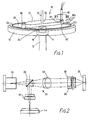
- an angular displacement transducer 10 has an input shaft 12.
- the shaft 12 is rotatably mounted by means of a bearing 14 in a hole 16 in the front plate 18 of the transducer housing.
- the shaft 12 extends through the hole 16 and is fastened to the centre of a rotatable disc 20 inside the transducer, whereby rotation of the shaft 12 causes corresponding rotation of the disc 20.
- the disc 20 is very similar to a conventional compact-disc used to store digital representations of an audio or video signal as an optical binary code.
- the disc 20 carries a continuous circular track 22 of a sequential pseudo-random binary code a short distance inside the outer edge of the disc 20.
- the code is represented on the disc as a sequence of binary features, defined on the track by areas of reflective and non reflective material.
- a reflective area corresponds to a logical 1
- a non reflective area corresponds to a logical 0.
- the pseudo-random code has the property that any set of 15 adjacent bits of the data code is unique, so that by reading a portion of 15 bits of the data code, the angular position of the disc 20 can be determined relative to a predetermined reference position.
- the disc 20 can be manufactured by a similar method to that used to manufacutre conventional compact discs by copying a master or prototype disc.
- the prototype disc 20 can be made from a square of a low expansion glass substrate.
- the glass is initially covered by a layer of evaporated chrome, which is highly optically reflective and which is covered in turn by a photoresist.
- the photoresist is then selectively removed using a laser, so as to leave the desired bit pattern covered and to expose the chrome around the bit pattern. In the bit pattern, the chrome is left covered wherever a logical 1 is to appear in the coded hack.
- the exposed chrome is then chemically etched away, and finally the remaining photoresist is removed to expose the chrome bit pattern.
- the square of glass substrate is then cut to form a disc, and a hole is formed in the centre for the end 24 of the shaft 12 to pass through.
- the size of the disc is determined by the width of each feature on the coded track, and the resolution of the angular displacement measurement required for the transducer. In the preferred embodiment, the width of each feature on the disc is approximately 1.9um.
- a disc of around 60mm in diameter is sufficient to carry the track.
- the diameter of the disc could be reduced to approximately 33mm.
- a photsensitive optical read head 30 is mounted on a support assembly 32 above the disc 20 to read a region of the coded track 22.
- the support assembly 32 contains magnetic coils (not shown) for controlling the height of the read head 30 above the surface of the disc 20. These coils are controlled by an autofocus mechanism described hereinafter.
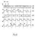
- the read head 30 contains an objective lens 34 and is part of an optical pick-up 33 shown in figure 2.
- the optical pick-up 33 also includes a semiconductor laser diode 36, a polarised beam splitter quarter wavelength plate 38, a collimating lens 40, a cylindrical lens 42 and a four quadrant photosensitive diode 44.
- the read head 30, the support assembly 32, and the optical pick-up 33 are all similar to the equivalent components used in a conventional compact-disc reading mechanism.
- light emitted by the laser diode 36 passes through the polarised beam splitter 38, and through the collimating lens 40, from which it emerges as substantially parallel light.
- the light is then focused by the objective lens 34 in the read head 30 to illuminate a small area on the surface of the disc 20.
- the autofocus mechanism described hereinafter is sufficiently accurate to ensure that the light is focused to an area no wider than the width of a feature on the track, i.e. 1.9um.
- the light illuminates an area of reflective chrome and is reflected back along its original path through the objective lens 34, through the collimating lens 40 to the polarised beam splitter 38.
- the light is there reflected through 90 o to pass through the cylindrical lens 42, and forms an illuminated image on the photosensitive diode 44.
- the diode 44 gives a "light" output indicative of a logical 1 feature being read from the coded track 22.
- the light illuminates a non reflective area where the chrome has been removed, and largely passes through the disc with little reflection. Virtually no light is reflected back through the optical pick-up 33 to the photosensitive diode 44.
- the diode 44 gives a "dark" output indicative of a logical 0 feature being read from the coded track 22.
- the objective lens 34 must be able to refocus as the disc surface deviates. An autofocus mechanism is therefore required to continuously monitor the focusing.
- the cylindrical lens 42 just prior to the photodiode 44 is used. Referring to figs. 3a,b,c, as the distance between the objective lens 34 and the disc 20 varies, the focal point of the system changes and the image 48 projected by the cylindrical lens changes shape. The change in the image on the photodiodes generates the focus correction signal.
- the objective lens needs to be moved until the signal on the four quadrant photodiode gives a circle as shown in figure 3a. The signals from the photodiodes 44a,b,c and d are then equal.
- the lens 34 is too near the disc 20, and the focal point is displaced from its focused position, causing the image 48 formed on the photodiodes 44 to be an ellipse.
- the output signal from the quadrant diodes 44a and 44c is greater than those from the quadrant diodes 44b and 44d.
- the lens 34 is too far from the disc 20, and the focal point is displaced in the opposite direction, causing the image formed on the photodiodes 44 to be another ellipse, rotated through 90 o .
- the output signal from the quadrant diodes 44b and 44d is therefore greater than those from the quadrant diodes 44a and 44c.
- the difference in signal from the photodiodes is used to continually correct the mechanism until a zero difference signal is obtained i.e. the laser beam is focused.
- the objective lens is displaced in the direction of the optical axis by a coil and permanent magnet structure. Control voltages from the focus drive circuit are applied to the focus coil and it moves up and down with respect to the magnet. There will be a maximum reaction time T in which the correct focusing will always be achieved.
- the autofocus of the read head is being used as designed for the C.D. player.
- the autofocus mechanism is only operative when light is being reflected onto the photodiode 44.
- a scanning mechanism is provided to scan the read head 30 over a region of the coded track 22, allowing it to read sequentially the features contained in the region, sufficient to read at least 15 bits. By scanning, a sufficient number of features can be read to enable the angular position of the disc 20 to be determined, even though the head 30 can itself only read one feature at any one moment, and the disc 20 may be stationary.
- the support assembly 32 is attached to one end 50 of a torsion bar 52.
- the other end (not shown) of the torsion bar 52 is fixed relative to the transducer housing.
- the scanning is achieved by forcing the read head 30, its support assembly 32 and the torsion bar 52 to oscillate at the resonant frequency of the torsion bar.
- the oscillation causes the read head to move back and forth circumferentially along the region of the track 22.
- the oscillations are cited by means of a magnet and an electromagnetic coil (not shown).
- the coil generates a circular magnetic field in a plane perpendicular to the axis of the torsion bar 52.
- the coil is attached to the read head 30, and the magnet is fixed relative to the transducer housing.
- the magnet and coil are equivalent to those used in a conventional compact disc reading mechanism for controlling radial movement of the read head.
- the resonant frequency of oscillation is in the range 50Hz to 250Hz, and is typically 100Hz. This frequency of oscillation is chosen so that the maximum scan velocity gives a minimum read time period per feature which is greater than the focusing reaction time T of the autofocus mechanism.
- each bit of data needs to be read to determine a unique angular position, and each bit of data is represented on the track 22 as a sequence of 3 features.
- the actual scan distance used is approximately 110um. This provides about 20% overscan to reduce the chances of an erroneous reading from missing data bits near the end points of the scan.
- the number of data bits read during the overall scan is approximately 19.
- two reference sensors are provided.
- the first sensor detects the end points of the oscillatory travel of the read head and the direction of scan. This allows the data read in one direction of scan to be separated from data read in the opposite direction in the next scan.
- a magnetic pick-up probe 104 is used for the first sensor.
- a magnet 103 is feed as a counterweight for the read head.
- the magnetic pick-up remains feed and measures the rate of change of magnetic flux as the magnet approaches and moves away from the probe.
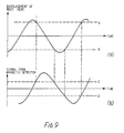
- the displacement of the read head during its oscillations about a mean point will be approximately a sinewave, which is approximately linear between the displacement positions shown as 'A' and 'B'. Data bits are only read from the disc during the linear region of the scan.
- the corresponding output from the pick-up will be a sinewave which is 90 o out of phase with the displacement of the read head.
- the output from the pick-up is above a threshold 'C', and during the linear region in the opposite direction of scan, the output is below a threshold 'D'.
- Comparators are chosen accordingly to detect when the output exceeds the thresholds 'C' and 'D', thereby determining the end points of the scan and the scan direction. This is essential because, as explained hereinafter for an anti-clockwise scan the code needs to be inverted and interpreted in reverse.
- the output from the magnetic pick-up is also applied in a positive feedback manner to the scanning drive magnetic coils, to maintain resonant oscillation of the support assembly and the torsion bar.
- the second sensor detects when the head is in a predetermined reference position relative to the transducer housing. This enables the 19 bits of data read during a scan to be aligned so that the correct 15 bits are selected for the angular position reading.
- an optical probe 60 is fixed relative to the transducer housing, and is directed to detect the presence of an optical reference mark 62.
- the reference mark 62 is mounted on the counterweight 39 which moves back and forth with the oscillatory scanning.
- the probe 60 comprises three optical fibres 64, 66, 68 arrranged in triangular formation, with their ends flush.
- the fibres 64 and 66 have their optical axes 64′ and 66′ located on the circumference of a circle having the axis of the torsion bar at its centre.
- the optical axis 68′ of the optical fibre 68 lies between the axes 66′ and 64′, and is offset radially.
- the remote end of the optical fibre 68 is connected to a light source (not shown), and the remote ends of the optical fibres 64 and 66 are connected to respective photosensitive detectors (not shown).
- the outputs from the photosensitive detectors are connected to a difference circuit (not shown). The output from the difference circuit is zero when the photosensitive detectors receive equal intensities of light.
- the optical reference mark 62 is provided by a line 70 of reflective chrome on a glass plate 72.
- the width of the line 70 is dependent on the dimensions of the optical probe 60, as explained below.
- the optical mark 62 moves in sympathy back and forth under the probe 60.
- the output from the difference circuit will be dependent on the displacement of the head 30 from the reference position, and is shown in figure.
- the probe 60 is directly over the reflective line 70.
- Light from the optical fibre 68 illuminates the line 70, and is reflected back down the fibres 64 and 66.
- the head 30 When the head 30 is not near the reference position, a small amount of light is always reflected back down at least one of the fibres 64 and 66, and the output signals from the photosensitive detectors are small, but different. The difference signal is also small, but not zero.
- the output from the difference circuit rises gradually from a small positive value until it reaches a maximum positive value.
- the output signal will drop through zero.
- the output signal will reach a minimum negative value before gradually rising to a small negative value.
- the binary data code is represented on the track 22 as a sequence of binary features.
- the features appear as areas 74 of reflective material denoting a logical 1, and areas 76 of non reflective material denoting a logical 0.
- the read head 30 scans an area of the track, it will read sequentially the features in that area. Say, for example, that during a portion of the scan, the head 30 reads the sequence of features shown in figure 6a, in the forward direction as shown by the arrow 80.
- the output 82 of the read head 30 is shown in figure 6c.
- the output is a continuous stream of pulses representing the features read.
- the first feature read for each data bit is a logical 1
- the last feature read for each data bit is a logical 0. This enables the individual output stream to be split into data bit frames containing the the 3 features for the data bit, since each data bit frame begins with a rising edge 83 of a high pulse.
- the middle feature corresponds to the data bit being represented.
- a short high pulse 84 corresponds to a logical 0 data bit
- a longer high pulse 86 corresponds to a logical 1 data bit.
- the regular occurrence of a rising edge 83 of a pulse enables a clock signal 88 to be derived from the output 82 of the head 30.
- the clock signal 88 can be used by the transducer circuitry for timing purposes to decide whether a data pulse is a long data pulse 86 representing a logical 1, or a short data pulse 84 representing a logical 0.
- the output 82 from the read head 30 is inverted, by an inverter (not shown) forming the signal 90 in figure 6f.
- the signal 90 has similar properties to the signal 82, in that (viewed from right to left) the bits of data code are represented by data pulses beginning with a regular rising edge 92 from which a clock pulse can be derived. The lengths of the pulses correspond to whether the data bit is a logical 1 or 0, but since the signal has been inverted, a long pulse 94 corresponds to a logical 0, and a short pulse 96 corresponds to a logical 1. The bit order moreover must be reversed.
- the number of bits of the code on the track 22 read when the head 30 is moving in the opposite direction to the direction of rotation will be greater than when the disc is stationary. Similarly the number of bits of code read when the head is moving in the same direction as that of rotation will be less than when the disc is stationary. If the rotational speed of the disc becomes sufficiently high that not enough bits of data are read during the scan in the direction of disc rotation, the reading is distarded, and only the reading taken in the opposite direction is used.
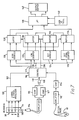
- Figure 7 is a block diagram showing the parts of the transducer, and how they are interconnected.
- the outputs from the four quadrant photodiode 44 are connected to a signal and focus processor 100, which performs the autofocus operation described hereinbefore.
- the processor 100 also has an output 102 that corresponds to the overall net signal read by the read head 30.
- the arrangement includes the magnetic first sensor 104 and the magnet 103, for detecting the end points of the approximately linear portion of head scan and the direction of the movement of the head during its oscillatory scan.
- the output from the magnetic sensor 104 is passed through comparators 106 and 107 connected in parallel.
- the output from the comparators are passed to an exclusive or logic gate 108, providing a net output 110.
- one comparator provides a true output wnen the signal above the threshold 'C', the other when the signal is below the threshold 'D'.
- the logic gate 108 provides a large (true) output only when one comparator output is true and the other is false, i.e. when the signal (figs. 9b,9c) is between the thresholds.
- the arrangement also includes the optical probe 60 described hereinbefore.
- the outputs from the photo sensitive detectors are connected to the difference amplifier 112, whose output is then passed to a comparator 114, giving a true output signal when the head is in the reference position.
- the output from the comparator 114, and the outputs 102 and 110 are each connected to a control circuit 116, which determines from the sensor outputs, the direction of scan during the oscillatory movement, the end points of the linear scan portions, and the instant that the read head 30 is in the reference position.
- the control circuit 116 has control lines 117 and 118 for controlling four counters arranged in parallel.
- the first counter 120 times the period of the duration of a data pulse when read by the read head 30.
- the second counter 122 times the subsequent period when no data pulse is being read.
- the third counter 124 counts the number of pulses read by the head during the portion of the scan after the detection of the reference position.
- the fourth counter 126 times the period from the detection of the reference position in a data bit frame to the end of the data bit frame in which the reference position occurred.
- the output from the first counter 120 is connected to a latch 128, and the output from the second counter 122 is connected to a latch 130.
- the output from the third counter 124 is connected to a buffer 132, and the output from the fourth counter 126 is connected to a buffer 134.
- the latches 128 and 130, and the buffers 132 and 134 are controlled by a control line 136 from the control circuit 116.
- the latches 128 and 130, and the buffers 132 and 134 interface with a microcomputer 138 which interprets the data pulses as the data code, and refers to a look up table 140 to obtain the angular position corresponding to the data code.
- the angular position is output by means of an output buffer 142, to enable the transducer to be connected to external measurement and monitoring apparatus.
- ths control ciurcuit sends a signal via the control line 118 to reset the counters 120, 122, 124 and 128.
- the first data pulse appears at the output 102 of the read head.
- the first counter 120 times the length of the data pulse, and the second counter then times the subsequent period until the next data pulse appears.
- the final values of the first and second counters 120 and 122 are stored in the latches 128, 130 respectively, and are transferred to the microcomputer 138 on the production of an interrupt signal by the control circuit 116 when the next data pulse appears at the output 102.
- the microcomputer 138 determines from the measured relative time period of the pulse and the subsequent time period until the next pulse, the value of the data bit in the pulse. If the period of the pulse is greater than the subsequent period to the next pulse, the data bit is a logical 1, otherwise the data bit is a logical 0.
- the control cirucit 116 sends a signal to start the third and fourth counters 124, 126.
- the values in the buffers are passed to the microcomputer 138 for processing.
- the value in the buffer 132 corresponds to the position in the scan of the data bit frame during which the reference position was detected. This enables the microcomputer to align the data bits so that the correct 15 bits of data are selected for the angular position determination.
- the value in the buffer 134 corresonds to the time period between the instant that the reference position was detected and the end of the data bit frame during which the reference position was detected. This is used by the microcomputer 138 in an interpolation method, described below, for improving the resolution of the angular position determination.
- the control circuit 116 sends reset pulses to the counters 120, 122, 124 and 126 and to the microcomputer 138.
- the microcomputer will have received approximately 19 bits of coded data but the correct 15 bits are selected for the angular position determination according to the accurance of the reference position.
- the microcomputer 138 accesses the look-up table 140 to obtain the angular position corresponding to the code read from the disc.
- the angular positions determinable by the transducer are quantised in angular values having a step width equal to the angular width 144 of each coded data bit 146 (3 features) on the track 22. Reading the code itself cannot provide an angular position to an accuracy corresponding to less than the angular width of the coded data pulse.
- a method of interpolation is used to improve the resolution.
- the method exploits the accurate nature of the reference position detector.
- the position of the reference position in the scan is denoted by the arrow 150.
- the buffer 132 will contain the value corresponding to the position in the scan of the coded data bit 148 during the reading of which the reference position was detected.
- the buffer 134 will contain a valve corresponding to the time period between the instant that the reference position was detected and the end of the data bit 148 during which the detection occurred.
- the latches 128 and 130 will contain valves corresponding to the overall time period taken to read the coded data bit 148.
- the microcomputer 138 compares the ratios of these time periods and derives a displacement value corresponding the displacement of the data bit 148 relative to the reference position 150.
- This displacement valve is combined with the angular position determined from the look up table to increase the resolution of the angular position signal.
- the improvement in the resolution will be dependent on how accurately the relative time periods described above can be measured, and will therefore be dependent on the frequency of the clock signal supplied to the counters 120, 122 and 126. For example, if the clock signal has 16 counts per data bit period, the position of the reference mark will be determined to one eighth of a coded data bit, giving an effective resolution three bits better than the coded data on the track 22.
- the two reference sensors 103, 104 and 60, 62 are replaced by a linear variable differential transformer displacement sensor, having a magnetic core movable axially within the coils of a differential transformer.
- the movable core is connected to the counterweight 39 on the support assembly 32, and projects therefrom in the scan direction.
- the body of the sensor containing the coils is feed to the housing. Scanning causes the core to reciprocate within the coils, producing an alternating output signal representative of the scan.
- the output signal is sufficiently accurate to define both the linear portion of the scan and the centre of the linear portion. Comparators are chosen to detect these positions, and to provide outputs for connection to the countrol circuit 116.
- the output from the position sensor is amplified, and applied in a positive feedback manner to the scanning drive magnetic coils, to maintain resonant oscillation of the support assembly and the torsion bar.
- the read head, its support assembly, the coded disc, and the control devices for controlling movement of the read head are all similar to corresponding devices used in a conventional compact disc reading mechanism.
- the embodiment can use a conventional compact disc reading mechanism, only minor modification being required.
- any problems encountered from misalignment between the support assembly and the disc could be overcome. If manufacturing tolerances make one head become more misaligned, they could be arranged to make the other head become more aligned. Only the output from the better aligned head would then be used.
Landscapes
- Physics & Mathematics (AREA)
- General Physics & Mathematics (AREA)
- Engineering & Computer Science (AREA)
- Theoretical Computer Science (AREA)
- Transmission And Conversion Of Sensor Element Output (AREA)
- Optical Transform (AREA)
- Length Measuring Devices With Unspecified Measuring Means (AREA)
Applications Claiming Priority (2)
| Application Number | Priority Date | Filing Date | Title |
|---|---|---|---|
| GB8900412 | 1989-01-09 | ||
| GB8900412A GB2228842B (en) | 1989-01-09 | 1989-01-09 | Relative position transducer |
Publications (2)
| Publication Number | Publication Date |
|---|---|
| EP0378351A2 true EP0378351A2 (de) | 1990-07-18 |
| EP0378351A3 EP0378351A3 (de) | 1992-04-22 |
Family
ID=10649792
Family Applications (1)
| Application Number | Title | Priority Date | Filing Date |
|---|---|---|---|
| EP19900300212 Withdrawn EP0378351A3 (de) | 1989-01-09 | 1990-01-09 | Wandler der relativen Lage |
Country Status (5)
| Country | Link |
|---|---|
| US (1) | US5171983A (de) |
| EP (1) | EP0378351A3 (de) |
| JP (1) | JPH02245615A (de) |
| CA (1) | CA2007221A1 (de) |
| GB (1) | GB2228842B (de) |
Cited By (6)
| Publication number | Priority date | Publication date | Assignee | Title |
|---|---|---|---|---|
| EP0630097A3 (de) * | 1993-06-07 | 1995-04-05 | Switched Reluctance Drives Ltd | Kodiergerät zur Erfassung der Ankerstellung in einer elektrischen Maschine. |
| US5650779A (en) * | 1995-03-28 | 1997-07-22 | Switched Reluctance Drives, Ltd. | Position encoder |
| US5723858A (en) * | 1995-03-28 | 1998-03-03 | Switched Reluctance Drives, Ltd. | Position encoder with fault indicator |
| WO2004013576A1 (de) * | 2002-07-30 | 2004-02-12 | Elgo-Electric Gmbh | Vorrichtung zur positions- und/oder längenbestimmung |
| WO2004033996A1 (de) * | 2002-10-08 | 2004-04-22 | Daimlerchrysler Ag | Geberrad |
| EP1783462A1 (de) * | 2005-11-08 | 2007-05-09 | Carl Freudenberg KG | Winkelmesseinrichtung |
Families Citing this family (4)
| Publication number | Priority date | Publication date | Assignee | Title |
|---|---|---|---|---|
| WO1997005456A1 (en) * | 1995-07-25 | 1997-02-13 | The Regents Of The University Of California | Compact disc based high-precision optical shaft encoder |
| GB2319079B (en) * | 1996-10-29 | 2000-07-12 | Baxter Int | Infusion pump monitoring encoder/decoder |
| US6327791B1 (en) | 1999-06-09 | 2001-12-11 | The Government Of The United States As Represented By The Secretary Of Commerce | Chain code position detector |
| US7191943B2 (en) * | 2004-07-28 | 2007-03-20 | Caterpillar Inc | Robust barcode and reader for rod position determination |
Family Cites Families (8)
| Publication number | Priority date | Publication date | Assignee | Title |
|---|---|---|---|---|
| CH365231A (fr) * | 1959-03-06 | 1962-10-31 | Genevoise Instr Physique | Convertisseur analogique numérique |
| US3505674A (en) * | 1966-06-27 | 1970-04-07 | Lynes Inc | Digital encoding device |
| US3540040A (en) * | 1966-12-29 | 1970-11-10 | Electro Dynamics & Telecom Ltd | Digital telemetry transducers |
| US4628298A (en) * | 1984-06-22 | 1986-12-09 | Bei Motion Systems Company, Inc. | Chain code encoder |
| GB2185359B (en) * | 1986-01-10 | 1990-01-17 | Rosemount Ltd | Optical displacement transducer |
| US4901073A (en) * | 1986-12-04 | 1990-02-13 | Regent Of The University Of California | Encoder for measuring the absolute position of moving elements |
| US4990909A (en) * | 1988-09-30 | 1991-02-05 | Yokogawa Electric Corporation | Revolution counter using a magnetic bubble device for multi-turn absolute encoder |
| US4970511A (en) * | 1989-12-04 | 1990-11-13 | Bei Electronics, Inc. | Method and apparatus for n/(n-x) resolver encoder |
-
1989
- 1989-01-09 GB GB8900412A patent/GB2228842B/en not_active Expired - Fee Related
-
1990
- 1990-01-05 CA CA002007221A patent/CA2007221A1/en not_active Abandoned
- 1990-01-05 US US07/461,880 patent/US5171983A/en not_active Expired - Fee Related
- 1990-01-09 JP JP2002419A patent/JPH02245615A/ja active Pending
- 1990-01-09 EP EP19900300212 patent/EP0378351A3/de not_active Withdrawn
Cited By (10)
| Publication number | Priority date | Publication date | Assignee | Title |
|---|---|---|---|---|
| EP0630097A3 (de) * | 1993-06-07 | 1995-04-05 | Switched Reluctance Drives Ltd | Kodiergerät zur Erfassung der Ankerstellung in einer elektrischen Maschine. |
| EP0713286A3 (de) * | 1993-06-07 | 1996-06-05 | Switched Reluctance Drives Ltd | |
| US5539293A (en) * | 1993-06-07 | 1996-07-23 | Switched Reluctance Drives Limited | Rotor position encoder having features in decodable angular positions |
| US5637972A (en) * | 1993-06-07 | 1997-06-10 | Switched Reluctance Drives, Ltd. | Rotor position encoder having features in decodeable angular positions |
| US5650779A (en) * | 1995-03-28 | 1997-07-22 | Switched Reluctance Drives, Ltd. | Position encoder |
| US5723858A (en) * | 1995-03-28 | 1998-03-03 | Switched Reluctance Drives, Ltd. | Position encoder with fault indicator |
| WO2004013576A1 (de) * | 2002-07-30 | 2004-02-12 | Elgo-Electric Gmbh | Vorrichtung zur positions- und/oder längenbestimmung |
| US7148817B2 (en) * | 2002-07-30 | 2006-12-12 | Elgo-Electric Gmbh | Device for positional and/or length determination |
| WO2004033996A1 (de) * | 2002-10-08 | 2004-04-22 | Daimlerchrysler Ag | Geberrad |
| EP1783462A1 (de) * | 2005-11-08 | 2007-05-09 | Carl Freudenberg KG | Winkelmesseinrichtung |
Also Published As
| Publication number | Publication date |
|---|---|
| EP0378351A3 (de) | 1992-04-22 |
| JPH02245615A (ja) | 1990-10-01 |
| GB2228842A (en) | 1990-09-05 |
| GB8900412D0 (en) | 1989-03-08 |
| GB2228842B (en) | 1993-01-06 |
| CA2007221A1 (en) | 1990-07-09 |
| US5171983A (en) | 1992-12-15 |
Similar Documents
| Publication | Publication Date | Title |
|---|---|---|
| RU2037860C1 (ru) | Оптический сканирующий блок | |
| EP0080212A1 (de) | Optische Speichervorrichtung | |
| US6930302B2 (en) | Method and apparatus for scanning an optical beam using an optical conduit | |
| US4933673A (en) | Encoder | |
| EP0189932A2 (de) | Spurfolgesystem zum steuerbaren Projizieren eines optischen Strahles auf eine optische Platte | |
| GB2029051A (en) | Apparatus for reading a disc-shaped record carrier | |
| US5171983A (en) | Relative position transducer for oscillating and scanning a read head over a coded track region | |
| EP0358689A1 (de) | Optischer lagekodierer | |
| EP0599806B1 (de) | Positionsdetektor | |
| US5825023A (en) | Auto focus laser encoder having three light beams and a reflective grating | |
| US5602388A (en) | Absolute and directional encoder using optical disk | |
| US6829118B1 (en) | Optical rotational position information detecting apparatus | |
| US4733069A (en) | Position encoder using a laser scan beam | |
| BE1007404A3 (nl) | Encoder element. | |
| US20220034686A1 (en) | Displacement measurement system | |
| EP0521196B1 (de) | Fokussiereinrichtung für Strichkodeleser | |
| US5177343A (en) | Symbol reader using differentiating circuit for light beam focusing | |
| JPH08506919A (ja) | 光走査装置 | |
| JP2000266567A (ja) | ロータリエンコーダ | |
| HUT61118A (en) | Detector circuit | |
| JPH0342610B2 (de) | ||
| JPH06185957A (ja) | 回転角測定装置 | |
| JPH0843132A (ja) | ロータリエンコーダ | |
| JPH03113316A (ja) | 光学式変位検出装置 | |
| JP2000352527A (ja) | 光学式エンコーダ |
Legal Events
| Date | Code | Title | Description |
|---|---|---|---|
| PUAI | Public reference made under article 153(3) epc to a published international application that has entered the european phase |
Free format text: ORIGINAL CODE: 0009012 |
|
| AK | Designated contracting states |
Kind code of ref document: A2 Designated state(s): AT BE CH DE FR IT LI NL SE |
|
| PUAL | Search report despatched |
Free format text: ORIGINAL CODE: 0009013 |
|
| AK | Designated contracting states |
Kind code of ref document: A3 Designated state(s): AT BE CH DE FR IT LI NL SE |
|
| STAA | Information on the status of an ep patent application or granted ep patent |
Free format text: STATUS: THE APPLICATION IS DEEMED TO BE WITHDRAWN |
|
| 18D | Application deemed to be withdrawn |
Effective date: 19921023 |