EP0379196A2 - Pumpengehäuse - Google Patents
Pumpengehäuse Download PDFInfo
- Publication number
- EP0379196A2 EP0379196A2 EP90101016A EP90101016A EP0379196A2 EP 0379196 A2 EP0379196 A2 EP 0379196A2 EP 90101016 A EP90101016 A EP 90101016A EP 90101016 A EP90101016 A EP 90101016A EP 0379196 A2 EP0379196 A2 EP 0379196A2
- Authority
- EP
- European Patent Office
- Prior art keywords
- casing
- pump
- volute
- casing body
- pump casing
- Prior art date
- Legal status (The legal status is an assumption and is not a legal conclusion. Google has not performed a legal analysis and makes no representation as to the accuracy of the status listed.)
- Granted
Links
- 239000012530 fluid Substances 0.000 claims abstract description 37
- 229910000831 Steel Inorganic materials 0.000 claims abstract description 7
- 239000010959 steel Substances 0.000 claims abstract description 7
- 239000002184 metal Substances 0.000 claims abstract description 5
- 230000003014 reinforcing effect Effects 0.000 claims description 19
- 238000005192 partition Methods 0.000 claims description 5
- 238000009740 moulding (composite fabrication) Methods 0.000 description 26
- 239000000543 intermediate Substances 0.000 description 11
- 230000003247 decreasing effect Effects 0.000 description 6
- 230000007423 decrease Effects 0.000 description 4
- 230000006866 deterioration Effects 0.000 description 4
- 230000002093 peripheral effect Effects 0.000 description 4
- 230000000694 effects Effects 0.000 description 3
- 238000004519 manufacturing process Methods 0.000 description 3
- 238000003466 welding Methods 0.000 description 3
- XLYOFNOQVPJJNP-UHFFFAOYSA-N water Substances O XLYOFNOQVPJJNP-UHFFFAOYSA-N 0.000 description 2
- 238000005266 casting Methods 0.000 description 1
- 238000010276 construction Methods 0.000 description 1
- 239000013013 elastic material Substances 0.000 description 1
- 238000000034 method Methods 0.000 description 1
- 238000012986 modification Methods 0.000 description 1
- 230000004048 modification Effects 0.000 description 1
- 238000007789 sealing Methods 0.000 description 1
- 229910001220 stainless steel Inorganic materials 0.000 description 1
- 239000010935 stainless steel Substances 0.000 description 1
Images





Classifications
-
- F—MECHANICAL ENGINEERING; LIGHTING; HEATING; WEAPONS; BLASTING
- F04—POSITIVE - DISPLACEMENT MACHINES FOR LIQUIDS; PUMPS FOR LIQUIDS OR ELASTIC FLUIDS
- F04D—NON-POSITIVE-DISPLACEMENT PUMPS
- F04D29/00—Details, component parts, or accessories
- F04D29/40—Casings; Connections of working fluid
-
- F—MECHANICAL ENGINEERING; LIGHTING; HEATING; WEAPONS; BLASTING
- F04—POSITIVE - DISPLACEMENT MACHINES FOR LIQUIDS; PUMPS FOR LIQUIDS OR ELASTIC FLUIDS
- F04D—NON-POSITIVE-DISPLACEMENT PUMPS
- F04D29/00—Details, component parts, or accessories
- F04D29/40—Casings; Connections of working fluid
- F04D29/42—Casings; Connections of working fluid for radial or helico-centrifugal pumps
- F04D29/426—Casings; Connections of working fluid for radial or helico-centrifugal pumps especially adapted for liquid pumps
- F04D29/4266—Casings; Connections of working fluid for radial or helico-centrifugal pumps especially adapted for liquid pumps made of sheet metal
-
- F—MECHANICAL ENGINEERING; LIGHTING; HEATING; WEAPONS; BLASTING
- F04—POSITIVE - DISPLACEMENT MACHINES FOR LIQUIDS; PUMPS FOR LIQUIDS OR ELASTIC FLUIDS
- F04D—NON-POSITIVE-DISPLACEMENT PUMPS
- F04D29/00—Details, component parts, or accessories
- F04D29/40—Casings; Connections of working fluid
- F04D29/42—Casings; Connections of working fluid for radial or helico-centrifugal pumps
- F04D29/44—Fluid-guiding means, e.g. diffusers
- F04D29/445—Fluid-guiding means, e.g. diffusers especially adapted for liquid pumps
Definitions
- the present invention relates to a pump casing manufactured by such as press forming of steel plate, and in particular, to a pump casing advantageously used for a centrifugal pump.
- a conventional pump casing manufactured by press forming of steel plate usually includes an outer casing of a cylindrical shape and a guide vane or a volute member which is separately fabricated and disposed inside of the outer casing to provide a fluid path.
- Fig. 8(a) is a longitudinal sectional view of a pump of prior art
- Fig. 8(b) is a sectional view taken on line A-A of Fig. 8(a).
- the volute casing defines a volute room 4 which guides fluid delivered from an impeller 1 to an discharge port 11.
- the volute room 4 is composed of side plates 5 and 6 disposed at each side, a peripheral plate 7 provided along the periphery of the side plates 5 and 6, and a volute vane or volute member 8 disposed in a space defined by the side plates and the peripheral plate and extended in a circumferential direction along a predetermined distance.
- These side plates 5 and 6, the peripheral plate 7 and the volute vane 8 are all manufactured by press forming of metal plates.
- the volute casing In going from a starting point 8a of the volute to a predetermined point 8b, the volute casing is radially deviated outwardly, thereby increasing the cross-sectional area of the fluid path within the volute casing in going towards the discharge port. Beyond the predetermined point 8b, the volute casing is deviated in an axial direction as denoted by 5a for increasing the cross-sectional area of the fluid path in going towards the discharge port 11. Thus, the cross-sectional area of the fluid path is gradually increased from the line 1-1 to line IV-IV [Fig. 8(b)].
- the casing can be manufactured with easier fabrication and lower cost in comparison with the manufacturing method of casting. Further, by deviating the volute fluid path in both radial and axial directions, it becomes possible to decrease the radial dimension of the pump to some extent, and to thereby decrease the cost.
- the object of the present invention is to solve the above-mentioned problems of prior arts, and to provide a pump casing which directly defines a fluid path without providing any separate fluid path member, i.e., volute vane, inside an outer cylindrical casing manufactured by press forming.
- the present invention is characterized in that the pump casing is at first formed by press forming a metal plate to form a casing body of a cylindrical cup shape having an opening portion at one side thereof and a closed bottom portion at the other side, and then by press forming said casing body so as to form a casing flange outwardly extending from said opening portion, an aperture serving as a suction port at said bottom portion, and a volute portion radially outwardly expanded from a cylindrical surface of said casing body at an axially intermediate portion thereof which is radially opposite to an impeller upon assembling.
- the present invention is characterized in that the maximum expanded portion of said volute portion formed by press forming at the intermediate cylindrical portion of said casing body is provided with an opening and this opening is connected with an discharge port through a nozzle which is shaped and welded so as to have a smooth fluid path.
- volute portion radially outwardly expanded from the surface of the intermediate cylindrical portion of the casing body is formed by so-called bulge-forming, i.e. through steps of setting the cylindrical cup shaped casing body formed with the outwardly extended casing flange at one opening side and the closed bottom portion at the other side in a female die having a recess on its inner surface corresponding to the volute portion, and of applying an internal pressure on the inner surface of the intermediate cylindrical portion and, at the same time, pushing upwards the bottom portion of the casing body for fitting the same to the inner surface of the female die.
- a cup-shaped cylindrical casing body having an opening portion on its one side and a closed bottom portion on the other side is manufactured by press forming a steel plate.
- the intermediate cylindrical portion of the casing body, which is opposite to the pump impeller upon assembling, is integrally formed on its inner surface with a volute portion radially gradually expanded by means of such as conventional bulge forming.
- the pump casing is fixed to the driving means through a casing cover fixed within the opening portion at one side of the casing body, a suction flange is connected with the suction port formed in the casing body and the impeller disposed inside of the casing is started to rotate.
- the fluid is sucked from the suction port formed at the bottom portion of the casing body through the suction flange, pressurized by the impeller, collected into the volute portion inside of the casing body, guided to the discharge port through the nozzle defining a smooth fluid path from the maximum expanded portion of the volute portion, and exhausted to the outside.
- the volute portion is integrally formed to gradually expand from the casing body as mentioned above, a fluid path inside the casing body becomes smoother in comparison with that of prior art. Further, the shape of the fluid path from the volute portion (expanded portion), through the nozzle to the discharge port has a smooth one.
- the pump according to the present invention includes neither step nor clearance between the volute portion and the pump casing (outer casing), thereby preventing any deterioration of the performance and any generation of noise.
- the plate thickness of the casing supporting the internal pressure may be decreased, and the stiffness of the casing is also increased.
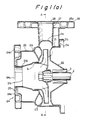
- Fig. 1(a) is a longitudinal view of a centrifugal pump having a pump casing made of steel plate according to an embodiment of the present invention, where the same numerals as in Fig. 8(a) indicate the same or similar portions.
- numeral 21 denotes a casing body.
- This casing body 21 is at first manufactured by press forming or deep drawing of a steel plate to form a cylindrical cup-shaped casing body having an opening portion surrounded by a flange on one side and a closed bottom portion on the other side, then setting said cup-shaped casing body 21, as shown in Figs.
- an expanded portion 21a corresponding to the volute portion which is to be disposed at a region radially opposite to the pump impeller upon assembling is formed in the intermediate cylindrical portion of the casing body 21.
- a casing flange 21b is formed at the opening portion on the driving side; and a casing front portion 21c and a pump suction port 21d axially projecting at the central portion thereof are formed at the bottom portion on the other side, i.e. suction side (left side in the figure).
- the above-mentioned casing flange 21b of the casing body 21 is fixed through a casing cover 22 to the driving side such as a bearing or a driving motor.
- the casing front portion 21c includes an outwardly expanded portion, inside of which is provided with a volute inner wall 23 which is opposites to a shroud of the impeller 1.
- a suction flange 24 having a concentric suction port 24a at the central portion thereof is connected with the suction port 21d of the casing body 21 by welding 24b.
- a reinforcing plate 25 is fixed and is supported on the casing body 21 through a cylindrical support member 26.
- the support member 26 also serves to prevent any inclination of the suction flange 24 due to an external force or impact acting on the flange.
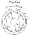
- An opening is provided at the widest portion of the volute expanded portion 21a where the fluid path sectional area is maximum and is located at the highest portion as shown in Fig. 3(a).
- the edge portion 211a of said opening has substantially a circular shape identical with that of the edge portion 27a of the nozzle 27 shown in Fig. 4(c), which is to be secured to the edge portion 211a by welding and connected with the discharge port 28 for defining a smooth fluid path.
- numeral 3 denotes a sealing device, 21e bolt holes provided in the casing flange 21b, 24d bolt holes provided in the flange surface 24c, 25a a reinforcing plate secured on an discharge flange 29.
- Fig. 3(b) and Fig. 3(c) show the shape of the volute portion thus formed.
- a volute room A which is defined by the circumferential expanded portion 21a is formed in the wall of the intermediate cylindrical portion of the casing body 21 by radially outwardly expanding the outer wall of the casing body 21 as stated above.
- the expansion is started from a circumferentially intermediate point of the casing body and the height H of which is gradually increased from H1 to H3 in the circumferential direction (counterclockwise direction in this case) while maintaining the width B thereof constant as shown in (o) to (iii) in Fig. 3(b) or Fig. 3(c).
- the sectional area of the flowing path of the volute room A is gradually increased toward the fluid flow direction.
- the expanded portion 21a may have trapezoidal or circular section as shown in Fig. 3(b) or Fig. 3(c).When the expanded portion is formed through the bulge forming, however, a circular section is preferable, as it has the following advantageous effects.
- the pump casing is mounted on the driving side through the casing flange 21b and the casing cover 22, and the impeller disposed inside of the pump casing is rotated. Then, by virtue of the above-mentioned arrangement, the fluid is sucked through the suction port 24a of the suction flange 24 and the suction port 21d formed in the bottom portion of the casing body 21, pressurized by the impeller 1, collected in the volute portion 21a in the casing body, guided to the discharge port 28 through the nozzle 27 which is connected with the widest portion of the volute expanded portion so as to define a smooth fluid path, and then exhausted to the outside.
- the pump casing according to the present invention includes, differently from the pump of prior art having a volute member internally interposed, neither step nor clearance between the volute portion and the pump outer casing, thereby preventing any deterioration of the pump performance or any generation of noise.
- the plate thickness of the casing for supporting the internal pressure may be decreased, and the stiffness of the casing is also increased.
- the size and number of bolts to be inserted into the bolt holes 21e of the casing flange 21b can be decreased accordingly.
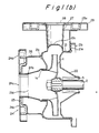
- Fig. 1(b) is a longitudinal sectional view of a centrifugal pump according to another embodiment of the present invention.
- the same numerals as in Fig. 1(a) indicate the same or similar portions.
- the volute inner wall 23 of the first embodiment is eliminated. It was confirmed that neither of pump performance nor the strength of the pump casing is notably deteriorated even if the volute inner wall 23 is eliminated, and thereby the construction of the pump casing may further be simplified.
- Fig. 2 is a longitudinal sectional view of a pump according to further embodiment of the present invention, where the same numerals as in Fig. 1 indicate the same portion.
- the volute front portion 21c′ is so formed as to have a shape substantially identical to that of the volute inner wall. According to this embodiment, when compared with the embodiment shown in Fig. 1(a), no volute inner wall is required and the manufacturing become easier, but the same pump performance can be obtained.
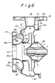
- Figs. 6 and 7 respectively show a longitudinal sectional view and a front view of a centrifugal pump according to a still further embodiment of the invention, and where the same numerals as in Fig. 1 indicate the same or similar portions.
- the casing body 21′ is constituted of two separate portions, i.e. a casing shell 21f and a reinforcing member 21g.
- the casing shell 21f is manufactured by press forming a stainless steel plate so as to have a fixing flange 21b on one end thereof, an expanded volute portion 21a at the intermediate cylindrical portion thereof, and an inwardly bent partition wall 21h on the other end of the casing shell.
- the expanded volute portion 21a is formed by radially expanding the intermediate cylindrical wall of the casing shell through bulge forming like in the embodiments stated above.
- a wall portion 21i of the casing shell 21f located on the suction side is formed with an outwardly projecting shoulder portion 21j for increasing the stiffness of the casing shell, and the before-mentioned inwardly bent partition wall 21h is integrally formed at the end of the wall portion 21i.
- On the inner periphery of the partition wall 21h is press-fitted a liner ring 30, on the inner periphery of which is fitted a tip portion 1a of the impeller 1 with a play maintained therebetween.
- the reinforcing member 21g To the outer surface of the wall portion 21i is secured the reinforcing member 21g to provide a double structure over a substantially whole area of the wall portion 21i.
- the reinforcing member 21g manufactured by press forming has a suction port 21d at its outer end portion, with which a separate suction flange 24 is connected by welding.
- each support member 26′ is fixed to the outer surface of the reinforcing member 21g and the other end of each support member 26′ is fixed to the side surface of the reinforcing plate 25.
- the numeral 31 denotes a liner ring fixed to the rear side of the impeller 1.
- the pump of this embodiment has the following advantageous effects in addition to the effects of the aforementioned embodiments.
Landscapes
- Engineering & Computer Science (AREA)
- Mechanical Engineering (AREA)
- General Engineering & Computer Science (AREA)
- Structures Of Non-Positive Displacement Pumps (AREA)
- Fluid-Driven Valves (AREA)
- Reciprocating Pumps (AREA)
- Glass Compositions (AREA)
- Compressor (AREA)
Applications Claiming Priority (4)
| Application Number | Priority Date | Filing Date | Title |
|---|---|---|---|
| JP8618/89 | 1989-01-19 | ||
| JP861889 | 1989-01-19 | ||
| JP1239397A JPH03105097A (ja) | 1989-09-14 | 1989-09-14 | 板金製うず巻ポンプケーシング |
| JP239397/89 | 1989-09-14 |
Publications (3)
| Publication Number | Publication Date |
|---|---|
| EP0379196A2 true EP0379196A2 (de) | 1990-07-25 |
| EP0379196A3 EP0379196A3 (en) | 1990-09-19 |
| EP0379196B1 EP0379196B1 (de) | 1993-10-20 |
Family
ID=26343176
Family Applications (1)
| Application Number | Title | Priority Date | Filing Date |
|---|---|---|---|
| EP90101016A Expired - Lifetime EP0379196B1 (de) | 1989-01-19 | 1990-01-18 | Pumpengehäuse |
Country Status (9)
| Country | Link |
|---|---|
| US (1) | US5040947A (de) |
| EP (1) | EP0379196B1 (de) |
| KR (1) | KR970010514B1 (de) |
| AT (1) | ATE96207T1 (de) |
| DE (3) | DE4001383A1 (de) |
| DK (1) | DK0379196T3 (de) |
| ES (1) | ES2047161T3 (de) |
| HK (1) | HK180996A (de) |
| IT (2) | IT223985Z2 (de) |
Cited By (10)
| Publication number | Priority date | Publication date | Assignee | Title |
|---|---|---|---|---|
| EP0406787A3 (en) * | 1989-07-05 | 1991-06-26 | Nowax S.R.L. | Case, particularly for centrifugal radial pumps, and method for manufacturing thereof |
| DE4101611A1 (de) * | 1991-01-11 | 1992-07-16 | Ebara Corp | Gehaeuse fuer eine kreiselpumpe aus metallblech |
| GB2266750A (en) * | 1992-05-07 | 1993-11-10 | Falmer Investment Ltd | Sheet-metal centrifugal pump casing. |
| DE4221463A1 (de) * | 1992-05-22 | 1993-11-25 | Wilo Gmbh | Kreiselpumpen mit spiralförmigem Pumpeninnenraum |
| EP0636794A1 (de) * | 1993-07-26 | 1995-02-01 | KSB Aktiengesellschaft | Flanschverstärkung |
| US6409474B1 (en) | 1998-10-30 | 2002-06-25 | Yangjiang New Yuehua Stainless Steel Pump Co. Ltd. | Centrifugal pump formed by pressing and welding and its manufacturing process |
| EP1020644A4 (de) * | 1997-09-30 | 2006-08-02 | Ebara Corp | Fluidumanlage, ein flausch für eine fluidumanlage und ein verfahren zur herstellung |
| EP2375006A1 (de) * | 2010-03-30 | 2011-10-12 | Snecma | Versteiftes Turbopumpengehäuse |
| CN102345607A (zh) * | 2011-10-14 | 2012-02-08 | 胡红伟 | 蜗壳式水泵及其机座 |
| CN102758790A (zh) * | 2011-04-28 | 2012-10-31 | 郑国� | 高效节能冲压化工离心泵 |
Families Citing this family (15)
| Publication number | Priority date | Publication date | Assignee | Title |
|---|---|---|---|---|
| EP0406418B1 (de) * | 1988-02-29 | 1995-02-15 | Ebara Corporation | Anschlussstück für leitungen in einer pumpe |
| JP2809487B2 (ja) * | 1989-07-05 | 1998-10-08 | 株式会社荏原製作所 | 遠心ポンプケーシング |
| US5235744A (en) * | 1989-07-05 | 1993-08-17 | Ebara Corporation | Method of manufacturing a centrifugal pump casing |
| JPH0758080B2 (ja) * | 1989-07-15 | 1995-06-21 | 株式会社荏原製作所 | 板金製うず巻ポンプケーシング |
| DE4005640A1 (de) * | 1990-02-22 | 1991-08-29 | Klein Schanzlin & Becker Ag | Spiralgehaeuse in blechbauweise |
| US5318403A (en) * | 1990-12-25 | 1994-06-07 | Ebara Corporation | Interstage casing for a pump made of sheet metal and method of manufacturing the same |
| JP2676450B2 (ja) * | 1991-01-11 | 1997-11-17 | 株式会社荏原製作所 | 板金製ポンプケーシング |
| US5266003A (en) * | 1992-05-20 | 1993-11-30 | Praxair Technology, Inc. | Compressor collector with nonuniform cross section |
| DE29716463U1 (de) * | 1997-09-15 | 1997-11-27 | KSB AG, 67227 Frankenthal | Kreiselpumpengehäuse |
| US6537024B2 (en) * | 1998-08-03 | 2003-03-25 | Industrial Technology Research Institute | Method for fabricating sheet metal pump casing |
| DE19838798C2 (de) * | 1998-08-26 | 2002-08-29 | Ind Tech Res Inst | Pumpengehäuse aus einem Metallblech und Verfahren zu seiner Herstellung |
| US6779974B2 (en) * | 2002-12-11 | 2004-08-24 | Polyvane Technology Corp. | Device of a volute channel of a pump |
| US6953321B2 (en) * | 2002-12-31 | 2005-10-11 | Weir Slurry Group, Inc. | Centrifugal pump with configured volute |
| DE202005004180U1 (de) * | 2005-03-14 | 2006-07-27 | Ebm-Papst Landshut Gmbh | Radialgebläse |
| CN100404874C (zh) * | 2006-01-21 | 2008-07-23 | 阳江市新力工业有限公司 | 一种冲压焊接食品泵 |
Family Cites Families (13)
| Publication number | Priority date | Publication date | Assignee | Title |
|---|---|---|---|---|
| US2677327A (en) * | 1949-02-24 | 1954-05-04 | Mcdonald Mfg Co A Y | Centrifugal pump construction |
| US2844100A (en) * | 1954-07-06 | 1958-07-22 | Kurt J Heinicke | Sheet metal centrifugal pump |
| US3412684A (en) * | 1967-07-27 | 1968-11-26 | Allis Chalmers Mfg Co | Pump casing |
| US3620042A (en) * | 1969-09-02 | 1971-11-16 | Airtex Products Div | Sheet metal water pump |
| DE2347915A1 (de) * | 1973-09-24 | 1975-04-03 | Speck Pumpen | Selbstansaugende kreiselpumpe |
| US4247250A (en) * | 1979-09-04 | 1981-01-27 | Allis-Chalmers Corporation | Fabricated pump casing |
| JPS5735676A (en) * | 1980-08-09 | 1982-02-26 | Sumitomo Metal Ind Ltd | Production of edged and melt sprayed steel plate |
| US4826401A (en) * | 1981-07-02 | 1989-05-02 | Tmt Research Development Inc. | Centrifugal pump |
| GB2172659A (en) * | 1985-03-19 | 1986-09-24 | Austin Rover Group | Cooling liquid pump for internal combustion engine |
| DE3517498C3 (de) * | 1985-05-15 | 1993-12-02 | Klein Schanzlin & Becker Ag | Kreiselpumpengehäuse |
| DE3517828A1 (de) * | 1985-05-17 | 1986-11-20 | Klein, Schanzlin & Becker Ag, 6710 Frankenthal | Pumpengehaeuse |
| US4775295A (en) * | 1985-05-17 | 1988-10-04 | Klein, Schanzlin & Becker Aktiengesellschaft | Centrifugal pump casing |
| FR2591514B1 (fr) * | 1985-12-12 | 1989-03-03 | Tissot Eugene | Procede de realisation de bossages annulaires sur un tuyau de descente d'eau, dispositif pour sa mise en oeuvre et tuyau obtenu |
-
1990
- 1990-01-18 DK DK90101016.5T patent/DK0379196T3/da active
- 1990-01-18 DE DE4001383A patent/DE4001383A1/de not_active Ceased
- 1990-01-18 AT AT90101016T patent/ATE96207T1/de not_active IP Right Cessation
- 1990-01-18 ES ES90101016T patent/ES2047161T3/es not_active Expired - Lifetime
- 1990-01-18 DE DE90101016T patent/DE69003955T2/de not_active Expired - Lifetime
- 1990-01-18 DE DE9000534U patent/DE9000534U1/de not_active Expired - Lifetime
- 1990-01-18 EP EP90101016A patent/EP0379196B1/de not_active Expired - Lifetime
- 1990-01-18 US US07/466,843 patent/US5040947A/en not_active Expired - Lifetime
- 1990-01-19 IT IT05282890U patent/IT223985Z2/it active IP Right Grant
- 1990-01-19 KR KR1019900000617A patent/KR970010514B1/ko not_active Expired - Lifetime
- 1990-01-19 IT IT67032A patent/IT1242308B/it active IP Right Grant
-
1996
- 1996-09-26 HK HK180996A patent/HK180996A/en not_active IP Right Cessation
Cited By (11)
| Publication number | Priority date | Publication date | Assignee | Title |
|---|---|---|---|---|
| EP0406787A3 (en) * | 1989-07-05 | 1991-06-26 | Nowax S.R.L. | Case, particularly for centrifugal radial pumps, and method for manufacturing thereof |
| DE4101611A1 (de) * | 1991-01-11 | 1992-07-16 | Ebara Corp | Gehaeuse fuer eine kreiselpumpe aus metallblech |
| GB2266750A (en) * | 1992-05-07 | 1993-11-10 | Falmer Investment Ltd | Sheet-metal centrifugal pump casing. |
| GB2266750B (en) * | 1992-05-07 | 1995-09-06 | Falmer Investment Ltd | Centrifugal pump |
| DE4221463A1 (de) * | 1992-05-22 | 1993-11-25 | Wilo Gmbh | Kreiselpumpen mit spiralförmigem Pumpeninnenraum |
| EP0636794A1 (de) * | 1993-07-26 | 1995-02-01 | KSB Aktiengesellschaft | Flanschverstärkung |
| EP1020644A4 (de) * | 1997-09-30 | 2006-08-02 | Ebara Corp | Fluidumanlage, ein flausch für eine fluidumanlage und ein verfahren zur herstellung |
| US6409474B1 (en) | 1998-10-30 | 2002-06-25 | Yangjiang New Yuehua Stainless Steel Pump Co. Ltd. | Centrifugal pump formed by pressing and welding and its manufacturing process |
| EP2375006A1 (de) * | 2010-03-30 | 2011-10-12 | Snecma | Versteiftes Turbopumpengehäuse |
| CN102758790A (zh) * | 2011-04-28 | 2012-10-31 | 郑国� | 高效节能冲压化工离心泵 |
| CN102345607A (zh) * | 2011-10-14 | 2012-02-08 | 胡红伟 | 蜗壳式水泵及其机座 |
Also Published As
| Publication number | Publication date |
|---|---|
| DE9000534U1 (de) | 1990-05-17 |
| IT1242308B (it) | 1994-03-04 |
| DE69003955D1 (de) | 1993-11-25 |
| DK0379196T3 (da) | 1994-02-07 |
| ES2047161T3 (es) | 1994-02-16 |
| DE69003955T2 (de) | 1994-02-17 |
| EP0379196A3 (en) | 1990-09-19 |
| IT9052828U1 (it) | 1990-07-20 |
| US5040947A (en) | 1991-08-20 |
| KR900011997A (ko) | 1990-08-02 |
| HK180996A (en) | 1996-10-04 |
| ATE96207T1 (de) | 1993-11-15 |
| IT223985Z2 (it) | 1995-10-05 |
| IT9067032A0 (it) | 1990-01-19 |
| IT9052828V0 (it) | 1990-01-19 |
| EP0379196B1 (de) | 1993-10-20 |
| KR970010514B1 (ko) | 1997-06-26 |
| DE4001383A1 (de) | 1990-07-26 |
| IT9067032A1 (it) | 1991-07-19 |
Similar Documents
| Publication | Publication Date | Title |
|---|---|---|
| EP0379196B1 (de) | Pumpengehäuse | |
| US5310310A (en) | Pump casing made of sheet metal | |
| EP0409106B1 (de) | Kreiselpumpengehäuse aus Metallblech | |
| JPH0718436B2 (ja) | 鋼板製中間ケーシング及び該中間ケーシングを用いた多段ポンプ | |
| US5184937A (en) | Centrifugal pump casing | |
| EP1469202B1 (de) | Mehrstufige pumpe | |
| KR100279507B1 (ko) | 토오크 컨버터의 임펠러 쉘과 상기 임펠러 쉘의 성형 방법 | |
| JP4433341B2 (ja) | シロッコファン用プレスハブの取付構造 | |
| JP2880295B2 (ja) | 2つのハウジング半部から成る再生ポンプ形圧縮機のハウジング | |
| CA1266797A (en) | Centrifugal pump housing | |
| JP3947345B2 (ja) | 多段ポンプ | |
| CN114576170B (zh) | 一种用于压缩机的下法兰结构及具有其的压缩机 | |
| JPH02278000A (ja) | ポンプケーシング及びその製造方法 | |
| JPH03105097A (ja) | 板金製うず巻ポンプケーシング | |
| JPH061079B2 (ja) | 板金製うず巻ポンプケーシング | |
| JPH0361698A (ja) | 板金製うず巻ポンプ | |
| JPH0579839B2 (de) | ||
| JPH07224782A (ja) | 多段うず巻きポンプ | |
| JP2886412B2 (ja) | 板金製ポンプケーシング及び該ポンプケーシングを備えた全周流型ポンプ | |
| JPH094593A (ja) | 電動遠心送風機 | |
| JP2024003479A (ja) | プレスインペラ及びポンプ装置 | |
| JPH0361699A (ja) | うず巻ポンプケーシング | |
| JPS6221759Y2 (de) | ||
| JP2023153688A (ja) | 回転電機 | |
| JP3004467B2 (ja) | 板金製ポンプケーシング |
Legal Events
| Date | Code | Title | Description |
|---|---|---|---|
| PUAI | Public reference made under article 153(3) epc to a published international application that has entered the european phase |
Free format text: ORIGINAL CODE: 0009012 |
|
| AK | Designated contracting states |
Kind code of ref document: A2 Designated state(s): AT BE CH DE DK ES FR GB GR IT LI LU NL SE |
|
| PUAL | Search report despatched |
Free format text: ORIGINAL CODE: 0009013 |
|
| AK | Designated contracting states |
Kind code of ref document: A3 Designated state(s): AT BE CH DE DK ES FR GB GR IT LI LU NL |
|
| 17P | Request for examination filed |
Effective date: 19910102 |
|
| 17Q | First examination report despatched |
Effective date: 19920406 |
|
| GRAA | (expected) grant |
Free format text: ORIGINAL CODE: 0009210 |
|
| ITF | It: translation for a ep patent filed | ||
| AK | Designated contracting states |
Kind code of ref document: B1 Designated state(s): AT BE CH DE DK ES FR GB GR IT LI LU NL SE |
|
| PG25 | Lapsed in a contracting state [announced via postgrant information from national office to epo] |
Ref country code: BE Effective date: 19931020 Ref country code: GR Free format text: LAPSE BECAUSE OF FAILURE TO SUBMIT A TRANSLATION OF THE DESCRIPTION OR TO PAY THE FEE WITHIN THE PRESCRIBED TIME-LIMIT Effective date: 19931020 |
|
| REF | Corresponds to: |
Ref document number: 96207 Country of ref document: AT Date of ref document: 19931115 Kind code of ref document: T |
|
| REF | Corresponds to: |
Ref document number: 69003955 Country of ref document: DE Date of ref document: 19931125 |
|
| ET | Fr: translation filed | ||
| PG25 | Lapsed in a contracting state [announced via postgrant information from national office to epo] |
Ref country code: LU Free format text: LAPSE BECAUSE OF NON-PAYMENT OF DUE FEES Effective date: 19940131 |
|
| REG | Reference to a national code |
Ref country code: DK Ref legal event code: T3 |
|
| REG | Reference to a national code |
Ref country code: ES Ref legal event code: FG2A Ref document number: 2047161 Country of ref document: ES Kind code of ref document: T3 |
|
| PLBI | Opposition filed |
Free format text: ORIGINAL CODE: 0009260 |
|
| 26 | Opposition filed |
Opponent name: GRUNDFOS A/S Effective date: 19940720 Opponent name: KSB AKTIENGESELLSCHAFT Effective date: 19940719 |
|
| NLR1 | Nl: opposition has been filed with the epo |
Opponent name: KSB AG. Opponent name: GRUNDFOS A/S. |
|
| EAL | Se: european patent in force in sweden |
Ref document number: 90101016.5 |
|
| PLBO | Opposition rejected |
Free format text: ORIGINAL CODE: EPIDOS REJO |
|
| APAC | Appeal dossier modified |
Free format text: ORIGINAL CODE: EPIDOS NOAPO |
|
| APAE | Appeal reference modified |
Free format text: ORIGINAL CODE: EPIDOS REFNO |
|
| APAC | Appeal dossier modified |
Free format text: ORIGINAL CODE: EPIDOS NOAPO |
|
| APAC | Appeal dossier modified |
Free format text: ORIGINAL CODE: EPIDOS NOAPO |
|
| PLBN | Opposition rejected |
Free format text: ORIGINAL CODE: 0009273 |
|
| STAA | Information on the status of an ep patent application or granted ep patent |
Free format text: STATUS: OPPOSITION REJECTED |
|
| 27O | Opposition rejected |
Effective date: 19981202 |
|
| NLR2 | Nl: decision of opposition | ||
| REG | Reference to a national code |
Ref country code: GB Ref legal event code: IF02 |
|
| APAH | Appeal reference modified |
Free format text: ORIGINAL CODE: EPIDOSCREFNO |
|
| PGFP | Annual fee paid to national office [announced via postgrant information from national office to epo] |
Ref country code: NL Payment date: 20060115 Year of fee payment: 17 |
|
| NLV4 | Nl: lapsed or anulled due to non-payment of the annual fee |
Effective date: 20070801 |
|
| REG | Reference to a national code |
Ref country code: CH Ref legal event code: PFA Owner name: EBARA CORPORATION Free format text: EBARA CORPORATION#11-1, HANEDA ASAHI-CHO#OTA-KU/TOKYO (JP) -TRANSFER TO- EBARA CORPORATION#11-1, HANEDA ASAHI-CHO#OTA-KU/TOKYO (JP) |
|
| PG25 | Lapsed in a contracting state [announced via postgrant information from national office to epo] |
Ref country code: NL Free format text: LAPSE BECAUSE OF NON-PAYMENT OF DUE FEES Effective date: 20070801 |
|
| PGFP | Annual fee paid to national office [announced via postgrant information from national office to epo] |
Ref country code: AT Payment date: 20090113 Year of fee payment: 20 Ref country code: DK Payment date: 20090113 Year of fee payment: 20 Ref country code: ES Payment date: 20090203 Year of fee payment: 20 |
|
| PGFP | Annual fee paid to national office [announced via postgrant information from national office to epo] |
Ref country code: DE Payment date: 20090115 Year of fee payment: 20 |
|
| PGFP | Annual fee paid to national office [announced via postgrant information from national office to epo] |
Ref country code: GB Payment date: 20090114 Year of fee payment: 20 Ref country code: CH Payment date: 20090114 Year of fee payment: 20 |
|
| PGFP | Annual fee paid to national office [announced via postgrant information from national office to epo] |
Ref country code: IT Payment date: 20090127 Year of fee payment: 20 Ref country code: SE Payment date: 20090108 Year of fee payment: 20 |
|
| PGFP | Annual fee paid to national office [announced via postgrant information from national office to epo] |
Ref country code: FR Payment date: 20090113 Year of fee payment: 20 |
|
| REG | Reference to a national code |
Ref country code: CH Ref legal event code: PL |
|
| REG | Reference to a national code |
Ref country code: DK Ref legal event code: EUP |
|
| REG | Reference to a national code |
Ref country code: GB Ref legal event code: PE20 Expiry date: 20100117 |
|
| EUG | Se: european patent has lapsed | ||
| REG | Reference to a national code |
Ref country code: ES Ref legal event code: FD2A Effective date: 20100119 |
|
| PG25 | Lapsed in a contracting state [announced via postgrant information from national office to epo] |
Ref country code: ES Free format text: LAPSE BECAUSE OF EXPIRATION OF PROTECTION Effective date: 20100119 |
|
| PG25 | Lapsed in a contracting state [announced via postgrant information from national office to epo] |
Ref country code: GB Free format text: LAPSE BECAUSE OF EXPIRATION OF PROTECTION Effective date: 20100117 |
|
| PG25 | Lapsed in a contracting state [announced via postgrant information from national office to epo] |
Ref country code: DE Free format text: LAPSE BECAUSE OF EXPIRATION OF PROTECTION Effective date: 20100118 |