EP0379986A2 - Procédé de réduction du temps de mesure et d'augmentation de la sensibilité de mesure de pression dans un système d'essai d'étanchéité et chambre d'essai associée - Google Patents
Procédé de réduction du temps de mesure et d'augmentation de la sensibilité de mesure de pression dans un système d'essai d'étanchéité et chambre d'essai associée Download PDFInfo
- Publication number
- EP0379986A2 EP0379986A2 EP90101074A EP90101074A EP0379986A2 EP 0379986 A2 EP0379986 A2 EP 0379986A2 EP 90101074 A EP90101074 A EP 90101074A EP 90101074 A EP90101074 A EP 90101074A EP 0379986 A2 EP0379986 A2 EP 0379986A2
- Authority
- EP
- European Patent Office
- Prior art keywords
- container
- pressure
- test chamber
- test
- chamber
- Prior art date
- Legal status (The legal status is an assumption and is not a legal conclusion. Google has not performed a legal analysis and makes no representation as to the accuracy of the status listed.)
- Granted
Links
Images
Classifications
-
- G—PHYSICS
- G01—MEASURING; TESTING
- G01M—TESTING STATIC OR DYNAMIC BALANCE OF MACHINES OR STRUCTURES; TESTING OF STRUCTURES OR APPARATUS, NOT OTHERWISE PROVIDED FOR
- G01M3/00—Investigating fluid-tightness of structures
- G01M3/02—Investigating fluid-tightness of structures by using fluid or vacuum
- G01M3/26—Investigating fluid-tightness of structures by using fluid or vacuum by measuring rate of loss or gain of fluid, e.g. by pressure-responsive devices, by flow detectors
- G01M3/32—Investigating fluid-tightness of structures by using fluid or vacuum by measuring rate of loss or gain of fluid, e.g. by pressure-responsive devices, by flow detectors for containers, e.g. radiators
- G01M3/3281—Investigating fluid-tightness of structures by using fluid or vacuum by measuring rate of loss or gain of fluid, e.g. by pressure-responsive devices, by flow detectors for containers, e.g. radiators removably mounted in a test cell
- G01M3/329—Investigating fluid-tightness of structures by using fluid or vacuum by measuring rate of loss or gain of fluid, e.g. by pressure-responsive devices, by flow detectors for containers, e.g. radiators removably mounted in a test cell for verifying the internal pressure of closed containers
Definitions
- the present invention relates to a method for reducing the measuring cycle time and for increasing the pressure measurement sensitivity in a density test method, in which, as an initial condition, a container to be tested is subjected to a pressure difference between internal and external pressure, and a pressure variable dependent on this pressure difference arises over time the tightness of the container is closed, as well as a test chamber for the tightness test of a container with an outer cross-sectional area that decreases in the axial direction of the container, the test chamber having a closable cavity for receiving the container, and a device for creating a pressure difference between the interior of the container and that between the cavity wall and the container formed container outer space, as an initial condition, and a pressure measuring device for measuring a pressure variable dependent on the pressure difference and the container density sweet.
- the present invention comprises an arrangement with a plurality of such test chambers and their use for the testing of filled and closed plastic cups, such as yogurt cups.
- Method for density testing in which a container to be tested has a pressure difference between inside and External pressure is subjected as an initial condition and the tightness of the container is known from a time course of a pressure variable dependent on this pressure difference.
- a test method is known from DE-OS 24 47 578, for example, to test the leakage of containers in the weld seam part of such containers.
- the container is subjected to the same pressure, inside and, along the most important wall sections, also on the outside due to the container opening, and a test channel is provided around the weld seam, separated from the volume under pressure. The development over time of the pressure in the test channel mentioned is registered as a measure of the tightness of the weld seam.
- the aim of the present invention is to reduce the measurement cycle time in such density test methods and at the same time to increase the pressure measurement sensitivity.
- test sealed, in particular filled, containers in test chambers for density by applying overpressure or underpressure in the test chamber relative to the inside of the container to be tested, then the system of the test chamber with a container to be tested from an excess or Vacuum source is separated, with which the initial pressure conditions are set in order to infer the density of the container from the pressure curve in the intermediate volume, ie the outer volume of the container between the test chamber and the container.
- the test cycle time per container essentially depends on the size of the outer container volume, i.e. on the difference volume between the test chamber and the container: the larger this difference volume, the longer the test cycle, because the larger it is, for both pressurization and evacuation , the more time it takes.
- cylindrical test chambers have usually been used for the density test of such closed, in particular also filled, containers.
- the above-mentioned invention is based on the knowledge that when testing closed containers, the same volume, namely the external volume of the container, determines both the test cycle time and the measurement sensitivity, and that when this volume is minimized, the test cycle time is minimized in the desired sense and the pressure measurement sensitivity is maximized.
- test chamber according to the invention of the above-mentioned type is distinguished by the wording of claim 2.
- the cavity is at least essentially geometrically similar to the shape of the container for a closed container, so that, like the container has a cross-sectional area that decreases in the axial direction of the container, also has a similarly decreasing open cross-sectional area, minimization of the container outer space is possible.
- the device for Creation of the pressure difference as an initial condition, and the pressure measuring device connected to the outside of the container.
- test chamber By designing the test chamber according to the invention according to the wording of claim 3 it is achieved that the shape of the test chamber is as simple as possible and that once a container has been inserted and checked, after opening the cover, it can be removed from the test chamber without further ado.
- the can bottom comprises an ejection piston which can be driven into the inside of the can in a controlled manner, so that after the container has been checked for leaks and the closure lid has been removed, the checked container can be dispensed by lifting the ejection piston.
- sleeve is essentially frustoconical.
- a corresponding evacuation or pressure line is connected outside.
- the case can arise where, particularly with flexible container walls, the container bulges out in this way when the intermediate volume is evacuated and at the mouth of the Suction line creates that the latter is closed.
- the wall material of the container should be prevented from forming and only becoming leaky under such additional deformation.
- a sieve insert in the chamber, be it only in predetermined areas along the wall of the chamber, such as to prevent the container wall from being sucked into a suction line, or be this along the entire chamber interior. or side wall to accommodate the container and ensure its shape.
- the test chamber is preferably arranged spatially in such a way that its opening is at the top.
- Containers to be tested can thus be let into the test chamber under the effect of gravity and can be dispensed after the test with the help of the ejection piston, and in particular
- a load on the weld seam to be tested between the cover film and the cup, which corresponds to the normal standing conditions of such containers, is ensured.
- This weld seam can hardly be reliably checked for leaks when such containers are "upside down” and the goods flow "downwards”.
- a sealingly closable detergent drain line opens into the chamber, with which the test chamber can be easily rinsed.
- the rinsing is carried out manually, or a sealingly closable supply line with a terminal nozzle for detergent can be provided, for example on the sealing cover, in order to clean the test chamber if necessary.
- test chamber is provided with a detergent drain line, which is to be sealed
- the organ which is already provided in the chamber namely the ejection piston, is preferably used to open or close the line in accordance with the wording of claim 10 .
- This embodiment is preferably implemented in accordance with the wording of claim 11 in such a way that the end piston comprises a piston plate and the line is opened or closed in a sealing manner by the side of the piston plate facing away from the sleeve interior
- the above-mentioned flushing agent drain line is opened during the ejection of a container that has just been checked and is sealed with the ejection piston retracted, thus in position, as for the leak test.
- test chambers are excellently suited to be combined to form a test arrangement according to claim 12, in order to carry out an in-line test of containers in production after they have been closed. Because of the short test cycles with the test chamber according to the invention, all containers of a production line can thus be checked for density, which has significant advantages over random tests.
- Such an arrangement according to the invention of a plurality of test chambers according to the invention is preferably designed as a carousel.
- test chamber according to the invention and therefore also the arrangement according to the invention of several such test chambers are particularly suitable for testing filled and closed plastic cups, such as yogurt cups.
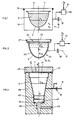
- a test chamber 1 is shown schematically, as it is used in a known manner for the density test of sealed containers 3, which, viewed in the direction of a container axis A, have reducing cross-sectional areas F3.
- the containers 3 are filled with filling material 5 and, for example, closed with a cover film 7, which is not connected to the container 3 at its periphery, such as, for example, being glued or welded.
- such containers can be plastic cups which are sealed with an aluminum foil 7.
- these containers 3 are introduced into the test chamber 1, which is then closed by means of a sealing cover 11 and seals 13. Between the container 3 and the Test chamber, consisting of cover 11 and chamber sleeve 15, an intermediate volume V z is defined, which is placed on a test pressure p z , which is different from the pressure inside the container 3.
- this is implemented via a pressurization line 17 with valve 19.
- the valve 19 is closed and the development of the pressure p z of the intermediate volume V z, for example by means of a haw sors 21, registered, preferably designed as a differential pressure sensor, which together with the intermediate volume pressure p z a reference pressure P R is supplied.
- a pressure increase in the intermediate volume V results in leakage of the container 3, and after closure of the valve because of the onset of pressure equalization z and vice versa of a test pressure for p upon application, which is greater than the pressure inside the container.
- gas volume In order to apply the test pressure p z to the intermediate volume V z , gas volume must be supplied to or removed from the intermediate volume V z , the greater the quantity, the greater the intermediate volume V z .
- the gas volume to be delivered for creating the test pressure p z has an effect, given the delivery rates of a pump or suction element (not shown) connected to the line 17, ie rectifies the period of time required to apply the test pressure: the smaller this intermediate volume V z , the shorter the time required for this.
- the gas volume flowing through the leak per unit of time is given for a given leakage, for a given test pressure p z and consequently for a given pressure difference between the intermediate volume V z and the interior of the container, so that the pressure change in the intermediate volume V z registered as a leakage measure increases with time , the lower the intermediate volume V z .
- test chamber 31 shown schematically in FIG. 2 comprises a bush 35 which is open on one side and has an opening 34, cross-sectional areas F 3 5 of the bush 35, viewed from the opening 34, being reduced.
- the reduction in the cross-sectional area F35 along the axis A3 vorzugieri preferably corresponds to the reduction in the cross-sectional area F3 of a container 3 to be inserted into the test chamber 31 to be tested, so that the wall of the container 3 and the inner wall of the test chamber 31 with the container 3 inserted are essentially equidistant from one another lie.
- the intermediate volume V z thus becomes minimal.
- a closure cover 33 is also provided on the test chamber 31 according to the invention, which sealingly closes the test chamber 31 by means of schematically illustrated seals 37 after the container 3 to be tested has been inserted. Applying the test pressure and registering the pressure curve in the intermediate volume V z takes place in the same way, as has already been explained with reference to FIG. 1.
- test chamber according to the invention is shown schematically in FIG. 3. As an example, it is designed to check for leaks in substantially frustoconical containers 3, such as those used for yoghurt, for example.
- the test chamber comprises a sleeve 39 which is shaped according to the outer contour of the container 3.
- the cross-sectional area of the sleeve 39, F39 tapers in the direction of the central axis A substantially conically from a sleeve opening 41 against the bottom 43 of the sleeve 39 and defines a cavity which is geometrically similar to the body of the container 3 in such a way that when a container 3 to be tested is inserted, there are essentially constant spacing ratios between its wall and the wall of the sleeve 39.
- In the opening region 41 of the sleeve 39 there is preferably a positioning circular channel for a protrusion that is usually provided for such containers edge provided with the cover foil welding (not shown).
- the test chamber also includes a closure cover 45 which, driven, as shown by the double arrow P, can be fed to or removed from the bush 39 in order to seal the test chamber by means of sealing members 43.
- an axially driven piston 47 Arranged at the bottom of the bush 39 is an axially driven piston 47, which is retrieved when a container 3 is inserted and during its inspection in the position shown and is then extended after opening the closure cover 45 in order to eject the container 3 which has just been tested.
- a flushing agent drain line 49 opens, which, as shown, the piston 47 which is returned, is sealed off by means of sealing members 51. This creates the possibility of rinsing the chamber after removing a tested container 3, which has leaked filling material into the test chamber during the pressure test, and after extending the piston 47, the detergent flowing out of the then opened detergent discharge line 49.
- a supply line for detergent if necessary with a nozzle, can be provided on the closure cover 45 (not shown).
- the test chamber is arranged spatially so that its opening 41 is at the top. This prevents the filling material in the container 3 from sinking onto the cover film, which would also impair a density test of the connecting seam, for example a weld seam, between the cover film 7 and the container wall.
- test chamber according to FIG. 3 comprises pressure supply and registration lines or organs, as explained in accordance with FIGS. 1 and 2.
- test chambers for example shown schematically in FIG. 3, are combined to form a test system, for example on a preferably horizontal carousel table (not shown) rotating about a vertical axis, so that in line with production and before the filled and closed containers are stacked for subsequent shipment, all containers are subjected to the density test in a test chamber according to the invention.
- a sieve insert (not shown) into the test chamber, for example in the form of a conical sieve tube open at the bottom, in which the container 3 to be tested is placed. With the help of such a sieve it is prevented that when the negative pressure is applied, the wall of the container is at best sealed against the wall of the test chamber.
- pressure connections can be provided, which, when the sealing part with film 7 of the container 3 is placed on a correspondingly shaped annular shoulder in the opening region 41 of the test chamber, ensure pressure equalization also to the intermediate volume V z ' located above the cover film 7.
Landscapes
- Physics & Mathematics (AREA)
- General Physics & Mathematics (AREA)
- Examining Or Testing Airtightness (AREA)
- Measuring Fluid Pressure (AREA)
- Detergent Compositions (AREA)
- Cleaning By Liquid Or Steam (AREA)
Priority Applications (2)
| Application Number | Priority Date | Filing Date | Title |
|---|---|---|---|
| EP94114412A EP0628801B1 (fr) | 1989-01-27 | 1990-01-19 | Chambre d'essai avec une conduite d'écoulement de produit de rincage |
| GR960402546T GR3021191T3 (en) | 1989-01-27 | 1996-09-30 | Process for reducing the measuring cycle time and for increasing the measuring pressure sensitivity of a leak-testing method, and associated test container. |
Applications Claiming Priority (2)
| Application Number | Priority Date | Filing Date | Title |
|---|---|---|---|
| DE3902435 | 1989-01-27 | ||
| DE3902435A DE3902435A1 (de) | 1989-01-27 | 1989-01-27 | Pruefkammer fuer gefuellte, verschlossene behaelter |
Related Child Applications (2)
| Application Number | Title | Priority Date | Filing Date |
|---|---|---|---|
| EP94114412.3 Division-Into | 1990-01-19 | ||
| EP94114412A Division EP0628801B1 (fr) | 1989-01-27 | 1990-01-19 | Chambre d'essai avec une conduite d'écoulement de produit de rincage |
Publications (3)
| Publication Number | Publication Date |
|---|---|
| EP0379986A2 true EP0379986A2 (fr) | 1990-08-01 |
| EP0379986A3 EP0379986A3 (fr) | 1991-10-23 |
| EP0379986B1 EP0379986B1 (fr) | 1995-03-29 |
Family
ID=6372929
Family Applications (2)
| Application Number | Title | Priority Date | Filing Date |
|---|---|---|---|
| EP94114412A Expired - Lifetime EP0628801B1 (fr) | 1989-01-27 | 1990-01-19 | Chambre d'essai avec une conduite d'écoulement de produit de rincage |
| EP90101074A Expired - Lifetime EP0379986B1 (fr) | 1989-01-27 | 1990-01-19 | Procédé de réduction du temps de mesure et d'augmentation de la sensibilité de mesure de pression dans un système d'essai d'étanchéité et chambre d'essai associée |
Family Applications Before (1)
| Application Number | Title | Priority Date | Filing Date |
|---|---|---|---|
| EP94114412A Expired - Lifetime EP0628801B1 (fr) | 1989-01-27 | 1990-01-19 | Chambre d'essai avec une conduite d'écoulement de produit de rincage |
Country Status (10)
| Country | Link |
|---|---|
| US (1) | US5042291A (fr) |
| EP (2) | EP0628801B1 (fr) |
| JP (2) | JP3104976B2 (fr) |
| AT (2) | ATE143134T1 (fr) |
| CA (3) | CA2368847C (fr) |
| DE (3) | DE3902435A1 (fr) |
| DK (2) | DK0628801T3 (fr) |
| ES (2) | ES2093481T3 (fr) |
| GR (2) | GR3015790T3 (fr) |
| HK (1) | HK1006876A1 (fr) |
Cited By (4)
| Publication number | Priority date | Publication date | Assignee | Title |
|---|---|---|---|---|
| DE19642099A1 (de) * | 1996-10-12 | 1998-04-16 | Leybold Vakuum Gmbh | Prüfung der Dichtheit von Verpackungen |
| WO2005008176A1 (fr) | 2003-07-17 | 2005-01-27 | Santen Pharmaceutical Co., Ltd. | Systeme pour inspecter des trous pour des recipients a trous |
| NL2009394C2 (en) * | 2012-08-30 | 2014-03-03 | A T Smit Holding | Apparatus and method for testing leak tightness of a package. |
| CN104236826A (zh) * | 2014-09-26 | 2014-12-24 | 清华大学 | 气袋产品的密封性检测装置及方法 |
Families Citing this family (25)
| Publication number | Priority date | Publication date | Assignee | Title |
|---|---|---|---|---|
| US5497654A (en) * | 1989-01-27 | 1996-03-12 | Lehmann; Martin | Method and apparatus for leak testing a container |
| US5333491A (en) * | 1989-01-27 | 1994-08-02 | Martin Lehmann | Method for reducing test cycle time and for improving measuring accuracy at a leak testing process |
| US5199296A (en) * | 1989-01-27 | 1993-04-06 | Martin Lehmann | Method for reducing test cycle time and for improving measuring accuracy at a leak testing process |
| US5333492A (en) * | 1990-03-20 | 1994-08-02 | Product Suppliers Ag | Process and apparatus for leak-testing a package |
| US5345814A (en) * | 1990-12-28 | 1994-09-13 | Whirlpool Corporation | Method and apparatus for testing vacuum insulation panel quality |
| US5226316A (en) * | 1992-03-20 | 1993-07-13 | Oscar Mayer Foods Corporation | Package leak detection |
| US5513516A (en) * | 1992-05-01 | 1996-05-07 | Visi-Pack, Inc. | Method and apparatus for leak testing a container |
| AU699979B2 (en) * | 1993-11-18 | 1998-12-17 | Martin Lehmann | Method of leak testing |
| US6082184A (en) * | 1997-05-27 | 2000-07-04 | Martin Lehmann | Method for leak testing and leak testing apparatus |
| EP0786655B1 (fr) * | 1997-05-07 | 2002-07-24 | Martin Lehmann | Procédé d'essai d'étanchéité d'un récipient fermé, chambre d'essai, dispositif de test et système d'inspection pour celui-ci |
| RU2253852C2 (ru) * | 1998-06-25 | 2005-06-10 | Мартин Леманн | Способ контроля герметичности емкостей и устройство для его осуществления |
| US6308556B1 (en) | 1999-12-17 | 2001-10-30 | Atc, Inc. | Method and apparatus of nondestructive testing a sealed product for leaks |
| US6584828B2 (en) | 1999-12-17 | 2003-07-01 | Atc, Inc. | Method and apparatus of nondestructive testing a sealed product for leaks |
| US6450011B1 (en) * | 2000-11-24 | 2002-09-17 | Mocon, Inc. | Pressure measurement method for gas leakage from sealed packages |
| US6513366B1 (en) | 2001-10-11 | 2003-02-04 | Packaging Technologies & Inspection Llc | Method and apparatus for package leak testing |
| JP4369977B2 (ja) * | 2005-01-10 | 2009-11-25 | モコン・インコーポレーテッド | 密封シールパッケージの漏れを検出するための器具と方法 |
| EP1848967B1 (fr) | 2005-02-02 | 2012-02-08 | Mocon, Inc. | Instrument et procede permettant de detecter et rapporter la taille des fuites dans un emballage hermetiquement ferme |
| WO2006088542A2 (fr) | 2005-02-14 | 2006-08-24 | Mocon, Inc. | Detection et communication de l'emplacement d'une fuite dans un emballage hermetique |
| PL2502043T3 (pl) * | 2009-11-20 | 2018-08-31 | Packaging Technologies & Inspection Llc | Stan próżni spoczynkowej dla sposobu i układu do testowania wycieków w oparciu o utratę podciśnienia |
| JP4924745B2 (ja) * | 2010-08-12 | 2012-04-25 | 東洋製罐株式会社 | 密封容器の密封検査方法、及び、その検査装置 |
| KR101223348B1 (ko) * | 2011-05-26 | 2013-01-16 | 금오공과대학교 산학협력단 | 솔라셀 제조용 진공챔버 모니터링 장치 |
| JP5673513B2 (ja) * | 2011-12-02 | 2015-02-18 | 東洋製罐株式会社 | 密封容器の密封検査方法、及び、その検査装置 |
| ITBO20130128A1 (it) * | 2013-03-26 | 2014-09-27 | Bonfiglioli Engineering S P A | Metodo ed apparato per la verifica di corpi siringa. |
| WO2016129997A1 (fr) * | 2015-02-09 | 2016-08-18 | Nederlandse Organisatie Voor Toegepast-Natuurwetenschappelijk Onderzoek Tno | Procédé et système de test d'étanchéité à l'air d'une enveloppe de bâtiment |
| DE102018111600A1 (de) * | 2018-05-15 | 2019-11-21 | Multivac Sepp Haggenmüller Se & Co. Kg | Verfahren zum erkennen von leckagen |
Family Cites Families (14)
| Publication number | Priority date | Publication date | Assignee | Title |
|---|---|---|---|---|
| NL91317C (fr) * | 1958-08-07 | 1959-06-15 | ||
| CH395584A (de) * | 1961-08-28 | 1965-07-15 | Hesser Ag Maschf | Verfahren und Vorrichtung zum zerstörungsfreien Prüfen von Packungen auf Luft- und Gasdichtheit |
| US3177704A (en) * | 1962-08-28 | 1965-04-13 | Robert H Stange | Leak testing method |
| US3517548A (en) * | 1968-06-20 | 1970-06-30 | Avco Corp | Means for and method of detecting leaks in the seal of a component |
| DE2009197A1 (en) * | 1970-02-27 | 1971-09-09 | Volkswagenwerk Ag | Gas leak testing device |
| CH524139A (de) * | 1970-05-29 | 1972-06-15 | Alusuisse | Vorrichtung zum Prüfen von Nahtstellen von mit Folien verschlossenen Behältern |
| US3795137A (en) * | 1972-09-12 | 1974-03-05 | Johnson & Son Inc S C | Leak detection apparatus for aerosol containers |
| SE368867B (fr) * | 1973-10-10 | 1974-07-22 | G Bergstrand | |
| JPS5834337A (ja) * | 1981-08-25 | 1983-02-28 | Dainippon Printing Co Ltd | 容器の漏れ検査装置 |
| DE8128651U1 (de) * | 1981-09-30 | 1983-03-31 | Unilever N.V., 3000 Rotterdam | Vorrichtung zur zerstoerungsfreien lecksuche an weichpackungen |
| JPS61246648A (ja) * | 1985-04-24 | 1986-11-01 | Toppan Printing Co Ltd | 漏れ検査装置 |
| US4791805A (en) * | 1985-06-07 | 1988-12-20 | Expertek, Inc. | Fuel tank leak detection apparatus |
| DE3528248A1 (de) * | 1985-08-07 | 1987-02-19 | Jagenberg Ag | Verfahren und vorrichtung zum kontrollieren der dichtheit von gefuellten, durch einen angesiegelten bzw. aufgeschweissten deckel od. dgl. verschlossenen behaelter |
| US4667506A (en) * | 1985-12-02 | 1987-05-26 | Crown Cork & Seal Canada Inc. | High pressure container tester |
-
1989
- 1989-01-27 DE DE3902435A patent/DE3902435A1/de not_active Withdrawn
-
1990
- 1990-01-19 DK DK94114412.3T patent/DK0628801T3/da active
- 1990-01-19 EP EP94114412A patent/EP0628801B1/fr not_active Expired - Lifetime
- 1990-01-19 ES ES94114412T patent/ES2093481T3/es not_active Expired - Lifetime
- 1990-01-19 AT AT94114412T patent/ATE143134T1/de not_active IP Right Cessation
- 1990-01-19 ES ES90101074T patent/ES2070198T3/es not_active Expired - Lifetime
- 1990-01-19 DE DE59010512T patent/DE59010512D1/de not_active Expired - Lifetime
- 1990-01-19 DE DE59008780T patent/DE59008780D1/de not_active Expired - Lifetime
- 1990-01-19 DK DK90101074.4T patent/DK0379986T3/da active
- 1990-01-19 EP EP90101074A patent/EP0379986B1/fr not_active Expired - Lifetime
- 1990-01-19 AT AT90101074T patent/ATE120542T1/de not_active IP Right Cessation
- 1990-01-23 CA CA002368847A patent/CA2368847C/fr not_active Expired - Lifetime
- 1990-01-23 CA CA002367877A patent/CA2367877C/fr not_active Expired - Lifetime
- 1990-01-23 CA CA002008372A patent/CA2008372C/fr not_active Expired - Lifetime
- 1990-01-24 US US07/469,398 patent/US5042291A/en not_active Expired - Lifetime
- 1990-01-29 JP JP02018810A patent/JP3104976B2/ja not_active Expired - Lifetime
-
1995
- 1995-04-14 GR GR950400920T patent/GR3015790T3/el unknown
-
1996
- 1996-09-30 GR GR960402546T patent/GR3021191T3/el unknown
-
1998
- 1998-06-22 HK HK98105974A patent/HK1006876A1/xx not_active IP Right Cessation
- 1998-11-12 JP JP10322640A patent/JP3093188B2/ja not_active Expired - Lifetime
Cited By (7)
| Publication number | Priority date | Publication date | Assignee | Title |
|---|---|---|---|---|
| DE19642099A1 (de) * | 1996-10-12 | 1998-04-16 | Leybold Vakuum Gmbh | Prüfung der Dichtheit von Verpackungen |
| WO2005008176A1 (fr) | 2003-07-17 | 2005-01-27 | Santen Pharmaceutical Co., Ltd. | Systeme pour inspecter des trous pour des recipients a trous |
| EP1647802A4 (fr) * | 2003-07-17 | 2007-05-23 | Santen Pharmaceutical Co Ltd | Systeme pour inspecter des trous pour des recipients a trous |
| US7325440B2 (en) | 2003-07-17 | 2008-02-05 | Santen Pharmaceutical Co., Ltd. | Hole inspection system for a pierced container |
| NL2009394C2 (en) * | 2012-08-30 | 2014-03-03 | A T Smit Holding | Apparatus and method for testing leak tightness of a package. |
| CN104236826A (zh) * | 2014-09-26 | 2014-12-24 | 清华大学 | 气袋产品的密封性检测装置及方法 |
| CN104236826B (zh) * | 2014-09-26 | 2017-06-13 | 清华大学 | 气袋产品的密封性检测装置及方法 |
Also Published As
| Publication number | Publication date |
|---|---|
| DE3902435A1 (de) | 1990-08-02 |
| EP0379986A3 (fr) | 1991-10-23 |
| HK1006746A1 (en) | 1999-03-12 |
| GR3015790T3 (en) | 1995-07-31 |
| DK0379986T3 (da) | 1995-08-28 |
| DE59008780D1 (de) | 1995-05-04 |
| CA2367877C (fr) | 2003-10-14 |
| JP3093188B2 (ja) | 2000-10-03 |
| JP3104976B2 (ja) | 2000-10-30 |
| CA2368847A1 (fr) | 1990-07-27 |
| EP0628801A2 (fr) | 1994-12-14 |
| CA2368847C (fr) | 2003-10-14 |
| EP0379986B1 (fr) | 1995-03-29 |
| HK1006876A1 (en) | 1999-03-19 |
| ATE143134T1 (de) | 1996-10-15 |
| JPH11218462A (ja) | 1999-08-10 |
| CA2008372A1 (fr) | 1990-07-27 |
| CA2367877A1 (fr) | 1990-07-27 |
| CA2008372C (fr) | 2003-10-14 |
| ES2070198T3 (es) | 1995-06-01 |
| EP0628801A3 (fr) | 1995-02-01 |
| JPH02232543A (ja) | 1990-09-14 |
| US5042291A (en) | 1991-08-27 |
| DK0628801T3 (da) | 1996-12-23 |
| GR3021191T3 (en) | 1996-12-31 |
| DE59010512D1 (de) | 1996-10-24 |
| ES2093481T3 (es) | 1996-12-16 |
| ATE120542T1 (de) | 1995-04-15 |
| EP0628801B1 (fr) | 1996-09-18 |
Similar Documents
| Publication | Publication Date | Title |
|---|---|---|
| EP0379986B1 (fr) | Procédé de réduction du temps de mesure et d'augmentation de la sensibilité de mesure de pression dans un système d'essai d'étanchéité et chambre d'essai associée | |
| EP3825674B1 (fr) | Procédé de formation et/ou de test d'une poche à l'intérieur d'un récipient | |
| DE69417516T2 (de) | Leckerfassung mit Wandvorsprung gegen ein Stocken | |
| DE69616649T2 (de) | Flaschenstopfenanordnung für wässrige Infusionen und Verfahren zu ihrer Herstellung | |
| DE4490301C2 (de) | Vorrichtung und Verfahren zur Entnahme von Proben eines Materials | |
| EP0048420A1 (fr) | Distributeur | |
| EP0833133A2 (fr) | Moyens de raccordement pour les appareils pour la détermination de la capacité des récipients | |
| EP0313678A1 (fr) | Méthode et dispositif pour examen d'étanchéité d'au moins un corps creux et utilisation de la méthode | |
| DE19918721A1 (de) | Verfahren und Vorrichtung zum Befüllen von nadelfreien Injektoren | |
| EP2161216A1 (fr) | Récipient pour substances pouvant s'écouler et procédé de dosage sans bulle de telles substances | |
| EP1724207A2 (fr) | Conteneur pour produits alimentaires ainsi que procédé pour le transport de produits alimentaires | |
| DE102016115398A1 (de) | Verfahren und Vorrichtung zur Prüfung von Faltenbälgen | |
| DE1473718A1 (de) | Verfahren und Vorrichtung zur Vakuum-Dichtheitspruefung einer mit Kunststoff ausgefuetterten Kartonverpackung | |
| DE202016008820U1 (de) | System zum Füllen einer Kartusche mit einer fließfähigen Komponente | |
| EP2930125B1 (fr) | Récipient en forme de bouteille dotée d'une poche intérieure | |
| EP3500833B2 (fr) | Procédé de contrôle de l'étanchéité d'un récipient flexible | |
| DE3906361C2 (de) | Vorrichtung zur Prüfung der Dichtigkeit eines flexiblen Kunststoffbehälters | |
| EP3201119B1 (fr) | Dispositif et procede pour remplissage d'un recipient sans equipement de mesurage | |
| DE102013002856A1 (de) | Verfahren und Vorrichtung zur Dichtigkeitskontrolle eines Behältnisses | |
| EP3222996B1 (fr) | Ensemble de suspension d'etalonnage, procede de fabrication d'un ensemble de suspension d'etalonnage et utilisation d'un ensemble de suspension d'etalonnage | |
| DE2847474C2 (de) | Vorrichtung zur Dichtigkeitsprüfung gasgefüllter Hohlkörper | |
| DE8904501U1 (de) | Vorrichtung zum Füllen und Entleeren von Proberöhrchen in der medizinischen und chemischen Analysetechnik | |
| DE2131465A1 (de) | Fluessigkeitsgefuellter verschlossener Behaelter aus flexiblem Kunststoff | |
| DE9411154U1 (de) | Vorrichtung zur Beeinflussung des Innendrucks von Tennisbällen | |
| WO2018152561A1 (fr) | Procédé de contrôle de l'étanchéité d'un récipient flexible |
Legal Events
| Date | Code | Title | Description |
|---|---|---|---|
| PUAI | Public reference made under article 153(3) epc to a published international application that has entered the european phase |
Free format text: ORIGINAL CODE: 0009012 |
|
| AK | Designated contracting states |
Kind code of ref document: A2 Designated state(s): AT BE CH DE DK ES FR GB GR IT LI LU NL SE |
|
| PUAL | Search report despatched |
Free format text: ORIGINAL CODE: 0009013 |
|
| AK | Designated contracting states |
Kind code of ref document: A3 Designated state(s): AT BE CH DE DK ES FR GB GR IT LI LU NL SE |
|
| 17P | Request for examination filed |
Effective date: 19920421 |
|
| 17Q | First examination report despatched |
Effective date: 19930416 |
|
| ITF | It: translation for a ep patent filed | ||
| GRAA | (expected) grant |
Free format text: ORIGINAL CODE: 0009210 |
|
| AK | Designated contracting states |
Kind code of ref document: B1 Designated state(s): AT BE CH DE DK ES FR GB GR IT LI LU NL SE |
|
| REF | Corresponds to: |
Ref document number: 120542 Country of ref document: AT Date of ref document: 19950415 Kind code of ref document: T |
|
| XX | Miscellaneous (additional remarks) |
Free format text: TEILANMELDUNG 94114412.3 EINGEREICHT AM 19/01/90. |
|
| REF | Corresponds to: |
Ref document number: 59008780 Country of ref document: DE Date of ref document: 19950504 |
|
| ET | Fr: translation filed | ||
| REG | Reference to a national code |
Ref country code: ES Ref legal event code: FG2A Ref document number: 2070198 Country of ref document: ES Kind code of ref document: T3 |
|
| GBT | Gb: translation of ep patent filed (gb section 77(6)(a)/1977) |
Effective date: 19950504 |
|
| REG | Reference to a national code |
Ref country code: GR Ref legal event code: FG4A Free format text: 3015790 |
|
| REG | Reference to a national code |
Ref country code: DK Ref legal event code: T3 |
|
| PLBE | No opposition filed within time limit |
Free format text: ORIGINAL CODE: 0009261 |
|
| STAA | Information on the status of an ep patent application or granted ep patent |
Free format text: STATUS: NO OPPOSITION FILED WITHIN TIME LIMIT |
|
| 26N | No opposition filed | ||
| REG | Reference to a national code |
Ref country code: GB Ref legal event code: IF02 |
|
| PGFP | Annual fee paid to national office [announced via postgrant information from national office to epo] |
Ref country code: GR Payment date: 20030130 Year of fee payment: 14 |
|
| PGFP | Annual fee paid to national office [announced via postgrant information from national office to epo] |
Ref country code: LU Payment date: 20030205 Year of fee payment: 14 |
|
| PGFP | Annual fee paid to national office [announced via postgrant information from national office to epo] |
Ref country code: BE Payment date: 20030225 Year of fee payment: 14 |
|
| PG25 | Lapsed in a contracting state [announced via postgrant information from national office to epo] |
Ref country code: LU Free format text: LAPSE BECAUSE OF NON-PAYMENT OF DUE FEES Effective date: 20040119 |
|
| PG25 | Lapsed in a contracting state [announced via postgrant information from national office to epo] |
Ref country code: BE Free format text: LAPSE BECAUSE OF NON-PAYMENT OF DUE FEES Effective date: 20040131 |
|
| BERE | Be: lapsed |
Owner name: *LEHMANN MARTIN Effective date: 20040131 |
|
| PG25 | Lapsed in a contracting state [announced via postgrant information from national office to epo] |
Ref country code: GR Free format text: LAPSE BECAUSE OF NON-PAYMENT OF DUE FEES Effective date: 20040804 |
|
| PGFP | Annual fee paid to national office [announced via postgrant information from national office to epo] |
Ref country code: AT Payment date: 20090113 Year of fee payment: 20 Ref country code: DK Payment date: 20090113 Year of fee payment: 20 Ref country code: ES Payment date: 20090218 Year of fee payment: 20 |
|
| PGFP | Annual fee paid to national office [announced via postgrant information from national office to epo] |
Ref country code: NL Payment date: 20090104 Year of fee payment: 20 Ref country code: DE Payment date: 20090115 Year of fee payment: 20 |
|
| PGFP | Annual fee paid to national office [announced via postgrant information from national office to epo] |
Ref country code: CH Payment date: 20090327 Year of fee payment: 20 Ref country code: GB Payment date: 20090114 Year of fee payment: 20 |
|
| PGFP | Annual fee paid to national office [announced via postgrant information from national office to epo] |
Ref country code: SE Payment date: 20090108 Year of fee payment: 20 Ref country code: IT Payment date: 20090127 Year of fee payment: 20 |
|
| PGFP | Annual fee paid to national office [announced via postgrant information from national office to epo] |
Ref country code: FR Payment date: 20090113 Year of fee payment: 20 |
|
| REG | Reference to a national code |
Ref country code: CH Ref legal event code: PL |
|
| REG | Reference to a national code |
Ref country code: DK Ref legal event code: EUP |
|
| REG | Reference to a national code |
Ref country code: GB Ref legal event code: PE20 Expiry date: 20100118 |
|
| NLV7 | Nl: ceased due to reaching the maximum lifetime of a patent |
Effective date: 20100119 |
|
| EUG | Se: european patent has lapsed | ||
| REG | Reference to a national code |
Ref country code: ES Ref legal event code: FD2A Effective date: 20100120 |
|
| PG25 | Lapsed in a contracting state [announced via postgrant information from national office to epo] |
Ref country code: ES Free format text: LAPSE BECAUSE OF EXPIRATION OF PROTECTION Effective date: 20100120 |
|
| PG25 | Lapsed in a contracting state [announced via postgrant information from national office to epo] |
Ref country code: GB Free format text: LAPSE BECAUSE OF EXPIRATION OF PROTECTION Effective date: 20100118 |
|
| PG25 | Lapsed in a contracting state [announced via postgrant information from national office to epo] |
Ref country code: NL Free format text: LAPSE BECAUSE OF EXPIRATION OF PROTECTION Effective date: 20100119 |
|
| PG25 | Lapsed in a contracting state [announced via postgrant information from national office to epo] |
Ref country code: DE Free format text: LAPSE BECAUSE OF EXPIRATION OF PROTECTION Effective date: 20100119 |