EP0380215A2 - Verfahren und Vorrichtung zum Spritzgiessen von mehrschichtigen Vorformlingen - Google Patents
Verfahren und Vorrichtung zum Spritzgiessen von mehrschichtigen Vorformlingen Download PDFInfo
- Publication number
- EP0380215A2 EP0380215A2 EP90300356A EP90300356A EP0380215A2 EP 0380215 A2 EP0380215 A2 EP 0380215A2 EP 90300356 A EP90300356 A EP 90300356A EP 90300356 A EP90300356 A EP 90300356A EP 0380215 A2 EP0380215 A2 EP 0380215A2
- Authority
- EP
- European Patent Office
- Prior art keywords
- injection
- passage
- primary
- nozzle
- materials
- Prior art date
- Legal status (The legal status is an assumption and is not a legal conclusion. Google has not performed a legal analysis and makes no representation as to the accuracy of the status listed.)
- Withdrawn
Links
Images

Classifications
-
- B—PERFORMING OPERATIONS; TRANSPORTING
- B29—WORKING OF PLASTICS; WORKING OF SUBSTANCES IN A PLASTIC STATE IN GENERAL
- B29C—SHAPING OR JOINING OF PLASTICS; SHAPING OF MATERIAL IN A PLASTIC STATE, NOT OTHERWISE PROVIDED FOR; AFTER-TREATMENT OF THE SHAPED PRODUCTS, e.g. REPAIRING
- B29C45/00—Injection moulding, i.e. forcing the required volume of moulding material through a nozzle into a closed mould; Apparatus therefor
- B29C45/17—Component parts, details or accessories; Auxiliary operations
- B29C45/76—Measuring, controlling or regulating
- B29C45/77—Measuring, controlling or regulating of velocity or pressure of moulding material
-
- B—PERFORMING OPERATIONS; TRANSPORTING
- B29—WORKING OF PLASTICS; WORKING OF SUBSTANCES IN A PLASTIC STATE IN GENERAL
- B29C—SHAPING OR JOINING OF PLASTICS; SHAPING OF MATERIAL IN A PLASTIC STATE, NOT OTHERWISE PROVIDED FOR; AFTER-TREATMENT OF THE SHAPED PRODUCTS, e.g. REPAIRING
- B29C45/00—Injection moulding, i.e. forcing the required volume of moulding material through a nozzle into a closed mould; Apparatus therefor
- B29C45/16—Making multilayered or multicoloured articles
- B29C45/1642—Making multilayered or multicoloured articles having a "sandwich" structure
- B29C45/1646—Injecting parison-like articles
-
- B—PERFORMING OPERATIONS; TRANSPORTING
- B29—WORKING OF PLASTICS; WORKING OF SUBSTANCES IN A PLASTIC STATE IN GENERAL
- B29C—SHAPING OR JOINING OF PLASTICS; SHAPING OF MATERIAL IN A PLASTIC STATE, NOT OTHERWISE PROVIDED FOR; AFTER-TREATMENT OF THE SHAPED PRODUCTS, e.g. REPAIRING
- B29C45/00—Injection moulding, i.e. forcing the required volume of moulding material through a nozzle into a closed mould; Apparatus therefor
- B29C45/16—Making multilayered or multicoloured articles
- B29C45/1642—Making multilayered or multicoloured articles having a "sandwich" structure
- B29C45/1643—Making multilayered or multicoloured articles having a "sandwich" structure from at least three different materials or with at least four layers
-
- B—PERFORMING OPERATIONS; TRANSPORTING
- B29—WORKING OF PLASTICS; WORKING OF SUBSTANCES IN A PLASTIC STATE IN GENERAL
- B29C—SHAPING OR JOINING OF PLASTICS; SHAPING OF MATERIAL IN A PLASTIC STATE, NOT OTHERWISE PROVIDED FOR; AFTER-TREATMENT OF THE SHAPED PRODUCTS, e.g. REPAIRING
- B29C45/00—Injection moulding, i.e. forcing the required volume of moulding material through a nozzle into a closed mould; Apparatus therefor
- B29C45/16—Making multilayered or multicoloured articles
- B29C45/1642—Making multilayered or multicoloured articles having a "sandwich" structure
- B29C45/1646—Injecting parison-like articles
- B29C2045/1648—Injecting parison-like articles the parison core layer being a barrier material
-
- B—PERFORMING OPERATIONS; TRANSPORTING
- B29—WORKING OF PLASTICS; WORKING OF SUBSTANCES IN A PLASTIC STATE IN GENERAL
- B29C—SHAPING OR JOINING OF PLASTICS; SHAPING OF MATERIAL IN A PLASTIC STATE, NOT OTHERWISE PROVIDED FOR; AFTER-TREATMENT OF THE SHAPED PRODUCTS, e.g. REPAIRING
- B29C45/00—Injection moulding, i.e. forcing the required volume of moulding material through a nozzle into a closed mould; Apparatus therefor
- B29C45/16—Making multilayered or multicoloured articles
- B29C45/1642—Making multilayered or multicoloured articles having a "sandwich" structure
- B29C2045/1656—Injecting the skin material through the central passage of the multiway nozzle
-
- B—PERFORMING OPERATIONS; TRANSPORTING
- B29—WORKING OF PLASTICS; WORKING OF SUBSTANCES IN A PLASTIC STATE IN GENERAL
- B29C—SHAPING OR JOINING OF PLASTICS; SHAPING OF MATERIAL IN A PLASTIC STATE, NOT OTHERWISE PROVIDED FOR; AFTER-TREATMENT OF THE SHAPED PRODUCTS, e.g. REPAIRING
- B29C2949/00—Indexing scheme relating to blow-moulding
- B29C2949/07—Preforms or parisons characterised by their configuration
- B29C2949/081—Specified dimensions, e.g. values or ranges
- B29C2949/0811—Wall thickness
- B29C2949/0819—Wall thickness of a layer
-
- B—PERFORMING OPERATIONS; TRANSPORTING
- B29—WORKING OF PLASTICS; WORKING OF SUBSTANCES IN A PLASTIC STATE IN GENERAL
- B29K—INDEXING SCHEME ASSOCIATED WITH SUBCLASSES B29B, B29C OR B29D, RELATING TO MOULDING MATERIALS OR TO MATERIALS FOR MOULDS, REINFORCEMENTS, FILLERS OR PREFORMED PARTS, e.g. INSERTS
- B29K2105/00—Condition, form or state of moulded material or of the material to be shaped
- B29K2105/25—Solid
- B29K2105/253—Preform
Definitions
- This invention relates in general to new and useful improvements in the formation by injection molding of preforms formed of plastic materials for use in the blow molding of multilayer containers.
- plastic material preforms and containers blow molded from such preforms are well known. It is also well known to form preforms of a multilayer construction which may include one or more barrier layers. Such preforms and modes of making the same are disclosed, for example, in the patent to Krishnakumar et al 4,609,516 granted September 2, 1986 and Beck 4,550,043 granted October 29, 1985. Further, it is known to provide apparatus for the injection molding of preforms wherein there are provided a plurality of metering pots and an injection nozzle which is provided with a plurality of coaxial flow passages, each nozzle passage having a separate gate controlled by acommon gate pin.
- This invention most particularly relates to the injection molding of preforms utilizing multiple materials and wherein in order to control the relative thickness and positions of layers within the interior of the preform, plastic materials are injected both sequentially and/or simultaneously into the preform cavity.
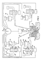
- FIG. 1 wherein there is illustrated an injection manifold system formed in accordance with this invention.
- the system being generally identified by the numeral 20.
- the system 20 is illustrated in conjunction with only a single cavity 22 within which there is injected plural plastic material to form a multilayer preform.
- the invention is applicable to a multiple cavity mold arrangement.
- the mold cavity 22 is formed within a mold 24 which is provided with an opening 26 into the cavity in which there is seated in sealed relation a multi-passage nozzle generally identified by the numeral 28.
- a multi-passage nozzle generally identified by the numeral 28.
- the nozzle 28 there are four flow passages. However, the number may be more or less as so desired. Further, as will be apparent hereinafter, at times only two of the nozzle passages will be utilized.
- the illustrated nozzle 28 includes a central passage 30 which is provided with a gate 32 for controlling the flow of plastic material therethrough.
- the nozzle 28 next includes a first outer passage 34 which is concentric or coaxial with the passage 30 and is provided with a flow control gate 36.
- the passage 34 is intended to receive a second or secondary material.
- a second outer flow passage 38 Surrounding the flow passage 34 is a second outer flow passage 38 which is concentric or coaxial with the passages 30, 34 and which is provided with a flow control gate 40.
- a third material is to be injected through the passage 38 although this third material may be identical with either the primary material or the secondary material.
- the nozzle 28 includes a third outer passage 42 which surrounds the passage 38 and which is provided with a flow control gate 44.
- the surrounding passage 42 is concentric or coaxial with the passages 30, 34, 38.
- the gates 32, 36, 40, 44 are selectively closed in sequence by a gate pin 46 which is positioned by means of a positioning devide 48 which is automatically controlled.
- a primary material is directed into the nozzle 28 by a first apparatus generally identified by the numeral 50.
- the apparatus 50 includes a metering pot 52 having therein a movable piston 54 whose position and rate of movement is controlled by an actuator 56.
- Molten plastic material is diverted into the metering pot 52 by way of a spool valve 56 having a spool 58 which is preferably rotatable, but which may be of the axially movable type.
- the spool 58 has a transverse flow passage 60 and the spool 58 is selectively positioned by means of a control device 62.
- the flowable plastic material is delivered to the metering pot 52 from a supply 64 which may be in the form of an extruder through a supply passage 66 which is coupled to the spool valve 56.
- Molten plastic material flowing through the spool valve 56 enters into a passage 68 which is, in turn, is coupled to a passage 70 which is in communication with the interior of the metering pot 52.
- the injection device 50 may supply molten plastic material to the nozzle 28 either from the metering pot 52 or directly from the extruder 64.
- molten plastic material is directed into the metering pot 52 by the extruder 64 either as the piston 54 is retracted, or after it is retracted.
- a primary material may be directed into the nozzle 28 through a flow passage 72 which forms a communication of the passage 70 by either advancing the piston 54 to empty the metering pot 52 or by utilizing the extruder 64.
- a primary material may be directed into the passage 30 slowly from the extruder 64 when the valve 56 is open. Flow through the nozzle 28 into the preform cavity 22 is controlled by the gate 32.
- Each of the devices 74, 76 and 78 includes a molten plastic supply 80 which may be in the form of an extruder although not necessarily so.
- the supply 80 is coupled by means of a flow passage 82 to a metering pot 84 through a spool valve 86 and a flow passage 88.
- the spool valve 86 is provided with a spool 90 which is illustrated as being rotatable and which is provided with a positioning device 92.
- the spool valve 86 is provided with a discharge passage 94 which is directed into a passage 96 which is coupled to a selective one of the passages of the nozzle 28.
- the spool 90 is provided with a reversely turned flow passage 98 and a through passage 100 in addition to having a closed position.
- the respective metering pot 84 With a piston 102 thereof retracted a selective distance by means of a control device 104 is filled by positioning the metering valve 74 in its through position and supplying molten plastic material from the supply 80. Then the spool 90 is rotated to its closed position. When it is desired to dispense the molten plastic material from the metering pot 84, the spool 90 is rotated to the illustrated position wherein molten plastic material may be directed from the metering pot 84 into that one of the several passages of the nozzle 28 to which the discharge passage 94 is connected.
- a principal feature of this invention is that as opposed to the prior practice of delivering molten plastic material to the nozzle 28 in sequence, the apparatus 20 may be operated so as to simultaneously supply to and through the nozzle 28 two or more of the molten plastic materials.
- the apparatus 20 may be operated so as to simultaneously supply to and through the nozzle 28 two or more of the molten plastic materials.
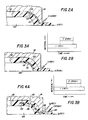
- Figures 2A, 2B wherein there is illustrated a method of forming a two material, three layer preform within the preform mold cavity 22 and about a mold core 106 conventionally positioned within the mold cavity 22.
- the supply passage 72 is coupled to the central passage 30 of the nozzle 28 while a second of the molten material supply devices is coupled to one of the surrounding passages of the nozzle 28.
- Flow of plastic material is controlled by a timing device generally identified by the numeral 108 and which controls the timed sequence operation of the various controls of the injection manifold assembly 20.
- a primary material is directed into the mold cavity for the full time of the injection of molten plastic material to form a preform.
- this may be effected by controlling the flow rate of the primary plastic material from the extruder 64 or by controlling the rate of supply of the primary material by the metering pot 52.
- a secondary material is injected into the preform mold cavity 22 from one of the surrounding passages of the nozzle 28.
- the injection of the secondary material is simultaneous with the injection of the primary material and is at a selected controlled rate with a selected beginning time and ending time.
- the relative rates of the injections of the two materials is such that the secondary material appears as a relatively thin layer 110 which is positioned adjacent the exterior of the preform which is being molded.
- the resultant preform is a two material, three layer preform with the primary material forming a relatively thick inner layer 112 and a relatively thin outer layer 114.
- the primary material instead of being directed into the cavity 22 through the central passage 30 of the nozzle 28, is injected into the cavity through one of the surrounding passages.
- the secondary material is injected into the cavity 22 through the central passage 30 to form a relatively thin inwardly offset layer 116 and dividing the preform into a relatively thin inner layer 118 and a relatively thick outer layer 120.
- the net result is a two material, three layer preform wherein the internal layer is offset towards the interior of the preform as opposed to being offset towards the exterior of the preform in accordance with the method of Figure 2A.
- the primary material is continuously injected with the injection being by way of the center passage 30 as at 122.
- the secondary material is injected as at 124 through one of the surrounding passages and more of the primary material is separately injected through another and outer surrounding passage as at 126.
- the net result is the primary material appears as an inner layer 128 and an outer layer 130 while the secondary material appears as a centrally located intermediate layer 132.
- the secondary material is injected as at 124 simultaneous with both injections of the primary material and wherein the injection of the primary material at 126 begins ahead of and continues after the injection of the secondary material 124.
- timing diagram of Figure 5B shows the initiation of the injection of the second material 136 at the instant the initial injection of the primary material discontinues, it is to be understood that there may be a slight separation or a minor overlap without materially imparing the injection process.
- the primary material is again delivered through the nozzle 28 and that delivery continues until the end of the injection. It will be seen that there is an overlap of the second injection of primary material 138 and the injection of the secondary material with the injection of the secondary material discontinuing before the final injection of the primary material.
- the net result is a two material, five layer preform construction.
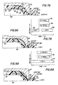
- the first injected primary material 152 is the first within the preform cavity 22 with the secondary material 154 dividing the primary material 152 to form relatively thin inner layer 156 and outer layer 158.
- the second delivered primary material identified by the numeral 160 and being injected through one of the surrounding passages, appears as a core within the secondary material with the core being outwardly offset so as to define in the secondary material, which functions as an intermediate layer, a relatively thick intermediate layer 162 and a relatively thin outer intermediate layer 164.
- the preform will be of a two material, five layer construction.
- FIG. 7A A further two material, five layer preform construction is found in Figure 7A. However, there are two separate injections of the secondary material with there being a second injection of secondary material as at 166 through another and outer surrounding nozzle passage.
- Figure 7B shows that the injection of the different materials in accordance with Figure 7A is the same as that of Figure 6B except for the additional injection of the secondary material 166. It is also to be noted that the second injection of the secondary material occurs at the same time as the first injection of the secondary material.
- the second injection 160 of the primary material appears as a central core 168 within the intermediate layer 154 with the intermediate layer 154 having on opposite sides of the core 168 generally like thickness in an intermediate layer 170 and outer intermediate layer 172.
- the primary material will preferably be a polyester, such as PET, and the secondary material will be a barrier material such as EVOH. It is to be understood, however, that the specific materials involved are known and of themselves do not form a part of this invention.
- FIG. 8A it will be seen that there is illustrated a method of making a three material, four layer preform by continuously injecting into the mold cavity 22 through the central passage 30 of the nozzle 28 a primary material 174 together with during part of the injection of the primary material 174 injecting a third material 176 and a secondary material 178 through surrounding ones of the passages of the nozzle 28.
- the net result is that the preform is primarily formed of the primary material 174 and is provided with a relatively thick inner intermediate layer of the third material 176 and a thin outer layer of the secondary material 178.
- FIG. 9A wherein there is illustrated the method of making still a different three material, four layer preform.
- the primary material 174 is again injected through the central passage 30 of the nozzle 28 and the injection is continuous.
- the method differs, however, in that the secondary material 178 is injected into the preform mold 22 through an inner one of the surrounding passages while the third material 176 is injected through an outer one of the surrounding passages of the nozzle 28.
- the net result is that the positions of the two intermediate layers is reversed so that the layer of the secondary material is disposed inwardly of the layer of the third material.
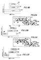
- FIG. 10A wherein there is illustrated a method of forming a three material, five layer preform.
- a primary material 180 there is an initial injection of a primary material 180 with this injection being through the central passage 30 of the nozzle 28.
- a quantity of secondary material 182 through an outer surrounding passage of the nozzle 28 which separates the primary material 180 into two relatively thin layers, an inner layer 184 and an outer layer 186.
- a third material 188 is injected through an inner one of the surrounding passages of the nozzle 28 to form a core within the secondary material 182 and dividing the secondary material 182 into a relatively thin inner intermediate layer 190 and a relatively thick outer intermediate layer 192.
- This is followed by a final injection of more of the primary material as at 194 through the central nozzle passage 30 to fill the mold cavity 22.
- the primary material and the secondary material will preferably be those described here and above with respect to the other embodiments.
- the third material will preferably be reground PET although as far as the method of this invention is concerned, it may be any suitable core forming material.
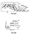
- FIG 12A it will be seen that there is illustrated a method of forming a three material, five layer preform. This is accomplished generally in the same manner as that shown in Figure 11A with the exception that there is a second injection of the secondary material, identified by the numeral 200 through an outermost one of the surrounding passages of the nozzle 28. As is clearly shown in Figure 12B, the two injections of the secondary material are simultaneous.
- the relationship of the various layers of the individual preforms is controlled not only by the timing of the timing diagrams, but also by the quantity of the injected material and the rate of injection which is controlled by the various metering pots as to size and rate of movement of their relative pistons.
- Flow of the various materials into the mold cavity 22 will, of course, be controlled by the gate pin 46 in conjection with the various gates while the positions of the various valves will control those materials which are directed to the nozzle 28 under pressure at any particular time.
- the extruder 64 may be utilized to complete the filling of the preform mold cavity 22 as, for example, in the case of the second injection of the primary material as at 194.
- Table 1 shows range of layer thickness for a 0.150 inch thick preform.
Landscapes
- Engineering & Computer Science (AREA)
- Manufacturing & Machinery (AREA)
- Mechanical Engineering (AREA)
- Blow-Moulding Or Thermoforming Of Plastics Or The Like (AREA)
- Injection Moulding Of Plastics Or The Like (AREA)
- Processing And Handling Of Plastics And Other Materials For Molding In General (AREA)
Applications Claiming Priority (2)
| Application Number | Priority Date | Filing Date | Title |
|---|---|---|---|
| US07/301,066 US4990301A (en) | 1989-01-25 | 1989-01-25 | Method and apparatus for injection molding of multilayer preforms |
| US301066 | 1989-01-25 |
Publications (2)
| Publication Number | Publication Date |
|---|---|
| EP0380215A2 true EP0380215A2 (de) | 1990-08-01 |
| EP0380215A3 EP0380215A3 (de) | 1991-07-10 |
Family
ID=23161782
Family Applications (1)
| Application Number | Title | Priority Date | Filing Date |
|---|---|---|---|
| EP19900300356 Withdrawn EP0380215A3 (de) | 1989-01-25 | 1990-01-12 | Verfahren und Vorrichtung zum Spritzgiessen von mehrschichtigen Vorformlingen |
Country Status (8)
| Country | Link |
|---|---|
| US (1) | US4990301A (de) |
| EP (1) | EP0380215A3 (de) |
| JP (1) | JPH02235607A (de) |
| KR (1) | KR900011553A (de) |
| CN (1) | CN1044430A (de) |
| AU (1) | AU4873390A (de) |
| BR (1) | BR9000291A (de) |
| CA (1) | CA2008266A1 (de) |
Cited By (13)
| Publication number | Priority date | Publication date | Assignee | Title |
|---|---|---|---|---|
| EP0596588A1 (de) * | 1992-11-04 | 1994-05-11 | Kasai Kogyo Co., Ltd. | Verfahren und Vorrichtung zum Pressformen |
| WO1996020074A1 (en) * | 1994-12-28 | 1996-07-04 | Continental Pet Technologies, Inc. | Method of cooling multilayer preforms |
| EP0839629A1 (de) * | 1996-10-02 | 1998-05-06 | Fried. Krupp AG Hoesch-Krupp | Verfahren zum Spritzgiessen von dreischichtigen Spritzlingen und Vorrichtung für die Durchfürung des Verfahrens |
| EP0887170A1 (de) * | 1997-06-27 | 1998-12-30 | Altoplast AG | Verfahren zum Herstellen eines Vorformlings sowie Vorformling zum Blasformen eines Behälters |
| EP0887169A1 (de) * | 1997-06-27 | 1998-12-30 | Altoplast AG | Verfahren zum Herstellen eines mehrschichtigen Vorformlings und nach dem Verfahren hergestellter Vorformling |
| US5897822A (en) * | 1995-10-13 | 1999-04-27 | Inter Tooling Services B.V. | Method of manufacturing hollow plastic articles |
| WO1999022926A1 (de) * | 1997-11-04 | 1999-05-14 | Otto Hofstetter Ag Werkzeug- Und Formenbau | Verfahren zur herstellung von mehrschichtigen vorformlingen |
| WO2002081172A1 (en) * | 2001-04-06 | 2002-10-17 | Kortec Inc. | Injection molding of multi-layer plastic articles |
| US6702978B1 (en) | 1996-04-30 | 2004-03-09 | Hans Kuehn | Process for manufacturing a plastic tube body |
| WO2006012713A2 (en) | 2004-08-06 | 2006-02-09 | Resilux | Preform for blowing a container and process for manufacturing therof |
| BE1016289A3 (nl) * | 2004-08-06 | 2006-07-04 | Resilux | Preform voor het blaasvormen van een houder en werkwijze voor het vervaardigen hiervan. |
| WO2009100506A3 (en) * | 2008-02-12 | 2010-10-07 | Resilux | Plastic preform and process for the manufacturing thereof to a container and the container and the use thereof |
| WO2013000044A2 (en) | 2011-05-18 | 2013-01-03 | Resilux | Hollow objects, particularly plastic preforms, resp. containers, with a barrier layer and injection moulding method, resp. device for manufacturing thereof |
Families Citing this family (47)
| Publication number | Priority date | Publication date | Assignee | Title |
|---|---|---|---|---|
| US5167896A (en) * | 1991-01-16 | 1992-12-01 | Kyowa Electric & Chemical Co., Ltd. | Method of manufacturing a front cabinet for use with a display |
| US5474735A (en) * | 1993-09-24 | 1995-12-12 | Continental Pet Technologies, Inc. | Pulse blow method for forming container with enhanced thermal stability |
| US5662856A (en) * | 1995-07-12 | 1997-09-02 | Imesco, Inc. | Low-pressure method for the preparation of hollow plastic articles |
| DE19530057A1 (de) * | 1995-08-16 | 1997-02-20 | Coronet Werke Gmbh | Bürste und Verfahren zu ihrer Herstellung |
| US5899500A (en) * | 1996-04-09 | 1999-05-04 | Ventra Group, Inc. | Staged coinjection molding process for producing variably flexible articles |
| US5840228A (en) * | 1996-10-08 | 1998-11-24 | Ritchey; Eugene B. | Method of creating indicia on a molded article |
| US5792397A (en) * | 1996-10-08 | 1998-08-11 | Ritchey; Eugene B. | Method of injection molding |
| CA2230768C (en) * | 1997-02-28 | 2007-02-13 | John W. Safian | Multilayer container package |
| US6123211A (en) | 1997-10-14 | 2000-09-26 | American National Can Company | Multilayer plastic container and method of making the same |
| CA2219257C (en) | 1997-10-23 | 2005-05-31 | Mold-Masters Limited | Sprue gated five layer injection molding apparatus |
| CA2219247C (en) * | 1997-10-23 | 2006-12-05 | Mold-Masters Limited | Injection molding apparatus having a melt bore through the front end of the pin |
| DE69929055T2 (de) | 1998-05-01 | 2006-07-20 | Duramed Pharmaceuticals Inc., Cincinnati | Verfahren zur spritzgussherstellung von vorrichtungen mit kontrollierter wirkstofffreisetzung und damit hergestellte vorrichtung |
| US6305563B1 (en) | 1999-01-12 | 2001-10-23 | Aptargroup, Inc, | One-piece dispensing structure and method and apparatus for making same |
| US6440350B1 (en) | 1999-03-18 | 2002-08-27 | Mold-Masters Limited | Apparatus and method for multi-layer injection molding |
| US6655945B1 (en) | 1999-03-18 | 2003-12-02 | Mold Masters Limited | Apparatus and method for multi-layer injection molding |
| US6398537B2 (en) | 1999-04-02 | 2002-06-04 | Mold-Masters Limited | Shuttle system for an apparatus for injection molding |
| US6196826B1 (en) | 1999-05-28 | 2001-03-06 | Mold-Masters Limited | Seepage system for an injection molding apparatus |
| US6428727B1 (en) * | 2000-02-17 | 2002-08-06 | The Elizabeth And Sandor Valyi Foundation, Inc. | Process and apparatus for preparing a molded article |
| CN1195620C (zh) * | 2000-10-19 | 2005-04-06 | 帝人株式会社 | 多层预成型体及其制造方法 |
| US6334774B1 (en) | 2000-11-24 | 2002-01-01 | Phillip Mark | Flow through applicator with resilient tip |
| KR20030006583A (ko) * | 2001-07-13 | 2003-01-23 | 주식회사 천경 | 다층벽 구조를 갖는 용기와 그 제조방법 및 장치 |
| US7033656B2 (en) * | 2002-04-12 | 2006-04-25 | Graham Packaging Pet Technologies, Inc. | Graded crystallization of container finishes |
| US7491359B2 (en) * | 2003-10-16 | 2009-02-17 | Graham Packaging Pet Technologies Inc. | Delamination-resistant multilayer container, preform, article and method of manufacture |
| US7510387B2 (en) * | 2004-06-30 | 2009-03-31 | Husky Injection Molding Systems Ltd. | Control system for dynamic feed coinjection process |
| WO2006062816A2 (en) * | 2004-12-06 | 2006-06-15 | Eastman Chemical Company | Polyester based cobalt concentrates for oxygen scavenging compositions |
| US7462319B2 (en) * | 2004-12-13 | 2008-12-09 | Husky Injection Molding Systems Ltd | Injection molding machine apparatus and method with moving platen injection and ejection actuation |
| US7651644B2 (en) * | 2006-05-31 | 2010-01-26 | Graham Packaging Company, Lp | Controlling delivery of polymer material in a sequential injection molding process |
| US20080093772A1 (en) * | 2006-10-06 | 2008-04-24 | Graham Packing Company, Lp | Method and apparatus for delivering sequential shots to multiple cavities to form multilayer articles |
| CN101722624B (zh) * | 2008-10-31 | 2013-05-15 | 东莞市鑫艺来塑胶制品有限公司 | 多色复合组装tpu注塑成型工艺 |
| WO2011112613A1 (en) | 2010-03-08 | 2011-09-15 | Kortec, Inc. | Methods of molding multi-layer polymeric articles having control over the breakthrough of the core layer |
| US8822001B2 (en) | 2010-04-27 | 2014-09-02 | Graham Packaging Company, L.P. | Delamination resistant multilayer containers |
| PL2593285T3 (pl) | 2010-07-16 | 2019-08-30 | Milacron Llc | Ulepszona nieprzepuszczalność gazowa pojemników formowanych wtryskowo |
| JP6035609B2 (ja) | 2010-11-24 | 2016-11-30 | ミラクロン エルエルシー | ヒートシール欠陥の防止方法および製品 |
| US9511526B2 (en) | 2011-08-23 | 2016-12-06 | Milacron Llc | Methods and systems for the preparation of molded plastic articles having a structural barrier layer |
| US8491290B2 (en) | 2011-10-21 | 2013-07-23 | Kortec, Inc. | Apparatus for producing non-symmetric multiple layer injection molded products |
| JP5817077B2 (ja) * | 2011-11-17 | 2015-11-18 | 株式会社吉野工業所 | 射出成形方法 |
| US9701047B2 (en) | 2013-03-15 | 2017-07-11 | Milacron Llc | Methods and systems for the preparation of molded plastic articles having a structural barrier layer |
| MX2016000333A (es) * | 2013-07-12 | 2016-06-21 | Plastipak Packaging Inc | Metodo de co-inyeccion, preforma y contenedor. |
| JP2015016661A (ja) * | 2013-07-12 | 2015-01-29 | 日精樹脂工業株式会社 | ホットランナーノズルとこのホットランナーノズルを用いた多層成形品成形用の金型、このホットランナーノズルを用いた金型への溶融樹脂送り込み方法、このホットランナーノズルを用いた多層成形方法 |
| CN104354272A (zh) * | 2014-10-28 | 2015-02-18 | 苏州广型模具有限公司 | 可自动控制流量的双浇口注塑模具 |
| JP5910953B2 (ja) * | 2015-03-05 | 2016-04-27 | 株式会社吉野工業所 | プリフォームの射出成形方法 |
| US11358313B2 (en) | 2017-02-21 | 2022-06-14 | Husky Injection Molding Systems Ltd. | Co-injection hot runner nozzle |
| WO2018209429A1 (en) * | 2017-05-17 | 2018-11-22 | Husky Injection Molding Systems Ltd. | Method of and apparatus for producing thin-walled molded containers |
| US12420466B2 (en) | 2019-09-19 | 2025-09-23 | Husky Injection Molding Systems Ltd. | Apparatus and method for coinjection of a multilayer molded article with a segmented internal layer |
| CN116367986A (zh) | 2020-07-29 | 2023-06-30 | 赫斯基注塑系统有限公司 | 改进多层往复螺杆注射模制机中的喷射可重复性的方法 |
| US12594702B2 (en) | 2020-10-21 | 2026-04-07 | Husky Injection Molding Systems Ltd. | Machine and method for injection molding multilayer articles having a high proportion of internal layer material |
| US20250360664A1 (en) * | 2022-06-15 | 2025-11-27 | Top Grade Molds Ltd. | Co-injection molding apparatus |
Family Cites Families (11)
| Publication number | Priority date | Publication date | Assignee | Title |
|---|---|---|---|---|
| US4035466A (en) * | 1972-09-27 | 1977-07-12 | Erhard Langecker | Method for central injection molding |
| US4052497A (en) * | 1973-09-21 | 1977-10-04 | Billion S.A. | Method of injection-moulding by injection of an article composed of at least three different materials |
| US4525134A (en) * | 1979-07-20 | 1985-06-25 | American Can Company | Apparatus for making a multi-layer injection blow molded container |
| CA1230806A (en) * | 1984-05-29 | 1987-12-29 | Clifton G. Slater | Ceric acid decontamination of nuclear reactors |
| JPS61108542A (ja) * | 1984-10-31 | 1986-05-27 | 三菱瓦斯化学株式会社 | 多層容器 |
| JPS61219644A (ja) * | 1985-03-26 | 1986-09-30 | 東洋製罐株式会社 | 延伸多層プラスチック容器の製法 |
| JPS62227712A (ja) * | 1986-03-31 | 1987-10-06 | Toyo Seikan Kaisha Ltd | オレフィン―ビニルアルコール共重合体の射出成形体及びその製法 |
| JPS6355A (ja) * | 1986-06-18 | 1988-01-05 | 山村硝子株式会社 | ポリエチレンテレフタレート樹脂製瓶及びその製造方法 |
| GB8616460D0 (en) * | 1986-07-05 | 1986-08-13 | Metal Box Plc | Manufacture of articles |
| JPS63252705A (ja) * | 1987-04-09 | 1988-10-19 | Japan Steel Works Ltd:The | 複層パリソンの成形装置 |
| US4957682A (en) * | 1988-01-19 | 1990-09-18 | Kamaya Kagaku Kogyo Co., Ltd. | Method of injection molding a three-layered container |
-
1989
- 1989-01-25 US US07/301,066 patent/US4990301A/en not_active Expired - Lifetime
-
1990
- 1990-01-12 EP EP19900300356 patent/EP0380215A3/de not_active Withdrawn
- 1990-01-22 CA CA002008266A patent/CA2008266A1/en not_active Abandoned
- 1990-01-24 BR BR909000291A patent/BR9000291A/pt not_active Application Discontinuation
- 1990-01-24 KR KR1019900000809A patent/KR900011553A/ko not_active Withdrawn
- 1990-01-24 AU AU48733/90A patent/AU4873390A/en not_active Abandoned
- 1990-01-25 CN CN90100409A patent/CN1044430A/zh active Pending
- 1990-01-25 JP JP2015961A patent/JPH02235607A/ja active Pending
Cited By (19)
| Publication number | Priority date | Publication date | Assignee | Title |
|---|---|---|---|---|
| US5389315A (en) * | 1992-11-04 | 1995-02-14 | Kasai Kogyo Co., Ltd. | Method and device for mold press forming |
| EP0596588A1 (de) * | 1992-11-04 | 1994-05-11 | Kasai Kogyo Co., Ltd. | Verfahren und Vorrichtung zum Pressformen |
| WO1996020074A1 (en) * | 1994-12-28 | 1996-07-04 | Continental Pet Technologies, Inc. | Method of cooling multilayer preforms |
| AU690419B2 (en) * | 1994-12-28 | 1998-04-23 | Graham Packaging Pet Technologies Inc. | Method of cooling multilayer preforms |
| US5897822A (en) * | 1995-10-13 | 1999-04-27 | Inter Tooling Services B.V. | Method of manufacturing hollow plastic articles |
| US6702978B1 (en) | 1996-04-30 | 2004-03-09 | Hans Kuehn | Process for manufacturing a plastic tube body |
| EP0839629A1 (de) * | 1996-10-02 | 1998-05-06 | Fried. Krupp AG Hoesch-Krupp | Verfahren zum Spritzgiessen von dreischichtigen Spritzlingen und Vorrichtung für die Durchfürung des Verfahrens |
| EP0887170A1 (de) * | 1997-06-27 | 1998-12-30 | Altoplast AG | Verfahren zum Herstellen eines Vorformlings sowie Vorformling zum Blasformen eines Behälters |
| EP0887169A1 (de) * | 1997-06-27 | 1998-12-30 | Altoplast AG | Verfahren zum Herstellen eines mehrschichtigen Vorformlings und nach dem Verfahren hergestellter Vorformling |
| WO1999022926A1 (de) * | 1997-11-04 | 1999-05-14 | Otto Hofstetter Ag Werkzeug- Und Formenbau | Verfahren zur herstellung von mehrschichtigen vorformlingen |
| CH692573A5 (de) * | 1997-11-04 | 2002-08-15 | Otto Hofstetter Ag Werkzeug Un | Verfahren zur Herstellung von mehrschichtigen Vorformlingen. |
| WO2002081172A1 (en) * | 2001-04-06 | 2002-10-17 | Kortec Inc. | Injection molding of multi-layer plastic articles |
| WO2006012713A2 (en) | 2004-08-06 | 2006-02-09 | Resilux | Preform for blowing a container and process for manufacturing therof |
| WO2006012713A3 (en) * | 2004-08-06 | 2006-03-09 | Resilux | Preform for blowing a container and process for manufacturing therof |
| BE1016289A3 (nl) * | 2004-08-06 | 2006-07-04 | Resilux | Preform voor het blaasvormen van een houder en werkwijze voor het vervaardigen hiervan. |
| US7842222B2 (en) | 2004-08-06 | 2010-11-30 | Resilux | Preform for blowing a container and process for manufacturing thereof |
| WO2009100506A3 (en) * | 2008-02-12 | 2010-10-07 | Resilux | Plastic preform and process for the manufacturing thereof to a container and the container and the use thereof |
| US8895120B2 (en) | 2008-02-12 | 2014-11-25 | Resilux | Plastic preform and process for the manufacturing thereof to a polychromatic container |
| WO2013000044A2 (en) | 2011-05-18 | 2013-01-03 | Resilux | Hollow objects, particularly plastic preforms, resp. containers, with a barrier layer and injection moulding method, resp. device for manufacturing thereof |
Also Published As
| Publication number | Publication date |
|---|---|
| JPH02235607A (ja) | 1990-09-18 |
| AU4873390A (en) | 1990-08-02 |
| CN1044430A (zh) | 1990-08-08 |
| BR9000291A (pt) | 1990-11-27 |
| US4990301A (en) | 1991-02-05 |
| EP0380215A3 (de) | 1991-07-10 |
| KR900011553A (ko) | 1990-08-01 |
| CA2008266A1 (en) | 1990-07-25 |
Similar Documents
| Publication | Publication Date | Title |
|---|---|---|
| EP0380215A2 (de) | Verfahren und Vorrichtung zum Spritzgiessen von mehrschichtigen Vorformlingen | |
| US5098274A (en) | Apparatus for injection molding of multilayer preforms | |
| US4710118A (en) | Apparatus for forming preforms with internal barrier | |
| EP0374247B1 (de) | Mehrschichtige giessdüse | |
| US6276914B1 (en) | Multiple gating nozzle | |
| US6099780A (en) | Method of three layer injection molding with sequential and simultaneous coinjection | |
| EP0034158B1 (de) | Mehrlagenartikel und verfahren zu dessen herstellung | |
| US6634877B2 (en) | Apparatus for injection molding over-molded articles | |
| EP0911136B1 (de) | Spritzgiessvorrichtung mit Angussdüsen und Verfahren zum Formen von fünfschichtigen Gegenständen | |
| US8021587B2 (en) | Method and apparatus for delivering sequential shots to multiple cavities to form multilayer articles | |
| EP0367123A2 (de) | Mehrschichtiger Rohling, Verfahren zur Herstellung des Rohlings und aus dem Rohling geformter Behälter | |
| US6648622B1 (en) | Apparatus and method for multi-layer injection molding | |
| AU721601B2 (en) | Molding multi-layered articles using coinjection techniques | |
| US20060157502A1 (en) | Tube with head made of multilayer materials and manufacturing process | |
| EP0033333B1 (de) | Apparat zur herstellung eines durch injektion geformten artikels | |
| JPH0483618A (ja) | 射出成形用マニホールド | |
| US6382946B1 (en) | Molding multi-layered articles using coinjection techniques | |
| JPH0698640B2 (ja) | 多層成形用ノズル | |
| CA1155263A (en) | Apparatus for making a multi-layer injection blow molded container | |
| WO2000062997A1 (en) | Molding multi-layered articles using coinjection techniques |
Legal Events
| Date | Code | Title | Description |
|---|---|---|---|
| PUAI | Public reference made under article 153(3) epc to a published international application that has entered the european phase |
Free format text: ORIGINAL CODE: 0009012 |
|
| AK | Designated contracting states |
Kind code of ref document: A2 Designated state(s): AT BE CH DE DK ES FR GB GR IT LI LU NL SE |
|
| PUAL | Search report despatched |
Free format text: ORIGINAL CODE: 0009013 |
|
| AK | Designated contracting states |
Kind code of ref document: A3 Designated state(s): AT BE CH DE DK ES FR GB GR IT LI LU NL SE |
|
| 17P | Request for examination filed |
Effective date: 19920106 |
|
| 17Q | First examination report despatched |
Effective date: 19930727 |
|
| STAA | Information on the status of an ep patent application or granted ep patent |
Free format text: STATUS: THE APPLICATION IS DEEMED TO BE WITHDRAWN |
|
| 18D | Application deemed to be withdrawn |
Effective date: 19931207 |