EP0381212A2 - Actionneur multidimensionnel électrostatique - Google Patents
Actionneur multidimensionnel électrostatique Download PDFInfo
- Publication number
- EP0381212A2 EP0381212A2 EP90102006A EP90102006A EP0381212A2 EP 0381212 A2 EP0381212 A2 EP 0381212A2 EP 90102006 A EP90102006 A EP 90102006A EP 90102006 A EP90102006 A EP 90102006A EP 0381212 A2 EP0381212 A2 EP 0381212A2
- Authority
- EP
- European Patent Office
- Prior art keywords
- electrode
- plane
- electrodes
- axis
- electrode body
- Prior art date
- Legal status (The legal status is an assumption and is not a legal conclusion. Google has not performed a legal analysis and makes no representation as to the accuracy of the status listed.)
- Withdrawn
Links
Images

Classifications
-
- H—ELECTRICITY
- H02—GENERATION; CONVERSION OR DISTRIBUTION OF ELECTRIC POWER
- H02N—ELECTRIC MACHINES NOT OTHERWISE PROVIDED FOR
- H02N1/00—Electrostatic generators or motors using a solid moving electrostatic charge carrier
- H02N1/002—Electrostatic motors
- H02N1/004—Electrostatic motors in which a body is moved along a path due to interaction with an electric field travelling along the path
-
- G—PHYSICS
- G11—INFORMATION STORAGE
- G11B—INFORMATION STORAGE BASED ON RELATIVE MOVEMENT BETWEEN RECORD CARRIER AND TRANSDUCER
- G11B7/00—Recording or reproducing by optical means, e.g. recording using a thermal beam of optical radiation by modifying optical properties or the physical structure, reproducing using an optical beam at lower power by sensing optical properties; Record carriers therefor
- G11B7/08—Disposition or mounting of heads or light sources relatively to record carriers
- G11B7/09—Disposition or mounting of heads or light sources relatively to record carriers with provision for moving the light beam or focus plane for the purpose of maintaining alignment of the light beam relative to the record carrier during transducing operation, e.g. to compensate for surface irregularities of the latter or for track following
- G11B7/0925—Electromechanical actuators for lens positioning
Definitions
- the present invention relates to an electrostatic-type multidimensional actuator and, more particularly, to a precisely positioning electrostatic-type multidimensional actuator which is suitable, for example, to a microminiature optical head and the like to be displaced in a multidimensional direction.
- a certain actuator is disclosed in Japanese Patent Unexamined Publication No. 62-262233, which kind of actuator generally utilizes piezoelectric effect to generate a potential difference when a voltage is impressed to piezoelectric materials such as barium titanate (BaTiO3) and leas titanate zirconate (abbreviated as PZT).
- barium titanate BaTiO3
- PZT leas titanate zirconate
- One object of the present invention is to provide an electrostatic-type multidimensional actuator which is reduced in size and weight.
- Another object of the invention is to provide a miniature light-weight electrostatic-type multidimensional actuator which is capable of generating a potential difference enough to precisely position an object.
- the electrostatic-type multidimensional actuator comprises: a first electrode body including a first plane electrode having a shape symmetrical with respect to the X axis, a second plane electrode symmetrical to the first plane electrode with respect to the Y axis orthogonal to the X axis, a third plane electrode having a shape symmetrical with respect to the Y axis, and a fourth plane electrode symmetrical to the third plane electrode with respect to the X axis which are mounted on an electrical insulator in combination with one another; a second electrode body serving as a fifth plane electrode, which extends opposite to and is spaced at a short distance from the first electrode body, including a configuration symmetrical with respect to the X and Y axes, a shape of the shadow projecting from the second electrode body to the first electrode assembly in a direction of the Z axis orthogonal to the X and Y axes being located inside the respective plane electrodes of the first electrode body;
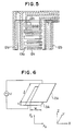
- Fig. 6 is an explanatory view of a force acting between two electrodes.
- a force in the X direction is referred to as F x and a force in the Z direction is as F z .
- L is a length of the overlapped portion between the electrodes in the Y direction
- w is a widthwise length of the overlapped portion between the electrodes in the X direction
- h is a distance between the electrodes in the Z direction
- V is a voltage applied to the electrode
- ⁇ is a dielectric constant of the space between the electrodes.
- the direction of either force F x or F z cannot be changed in the reverse direction by controlling the voltage.
- the electrodes in a pair have to be set at a location where the electrode 2A corresponding to the electrode 3A is set at the opposite side in the negative direction relative to the location shown in the figure. Further, it is necessary to position the electrode 2A at a location where the electrode 2A has to be set below the electrode 3A in the negative direction of the Z axis, in order to cause the force in the negative direction on the Z axis.
- the movable electrode is positionally displaced by an attraction force between the fixed electrode and itself, so that the distance h between the fixed and movable electrodes is shortened, and it is thus impossible to control the generated force F z only by the voltage.
- the lateral driving force F x can be determined only by the voltage V, as be understood from the equation (1), it is easier to utilize the lateral driving force F x in order to precisely control positioning of the movable electrode.
- the suction force F z is larger than the lateral driving force F x .
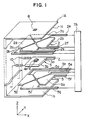
- FIG. 1 to 3 there is illustrated a three-dimensional actuator for driving a one-chip optical head in three directions of the X, Y and Z axes.
- reference numeral 1A designates a holder made from an electrical insulator
- reference numeral 2 designates an upper fixed electrode corresponding to a first electrode assembly.
- the upper fixed electrode 2 is provided in combination with a first plane electrode 2b having a shape symmetrical with respect to the X axis, a second plane electrode 2d symmetrical to the first plane electrode 2b with respect to the Y axis orthogonal to the X axis, a third plane electrode 2a having a shape symmetrical with respect to the Y axis, and a fourth plane electrode symmetrical to the third plane electrode with respect to the X axis.
- These plane electrodes are secured to the lower surface 1a of an upper portion of the holder 1.
- the upper fixed electrode 2 comprises the four plate-like electrodes 2a, 2b, 2c and 2d, those respective plane electrodes having configurations obtained from equally separating a generally square plane electrode into four sections along its diagonal lines, and they have apex portions each with an angle of 45°.
- the four electrodes are disposed opposite to one another on one plane in such a manner that the respective apex portions of the electrodes are directed toward the central point of the upper fixed electrode 2, while each electrode is spaced apart from the adjacent electrode at an equal distance.
- the electrodes which are located in the above-mentioned manner respectively include elongations 2e, 2f, 2g and 2h extending in the same direction.
- Reference numeral 3 designates a movable electrode which is a second electrode body disposed in parallel with the upper fixed electrode 2 interposing a short distance h1 therebetween (see Fig. 3).
- the movable electrode 3 is in a square shape symmetrical with respect to both directions of the X and Y axes.
- a shape of the shadow projecting from the movable electrode 3 in the Z direction orthogonal to the X and Y axes is located inside the respective plane electrodes 2a to 2d of the upper fixed electrode 2.
- the vertical axis of the square movable electrode 3 coincides with that of the upper fixed electrode 2, as shown in Fig. 2.
- the respective plane electrodes 2a, 2b, 2c and 2d of the upper fixed electrode 2 and the movable electrode 3 are vertically spaced from each other, in the state that the respective plane electrodes have the same overlapped area by the movable electrode 3.
- This movable electrode 3 includes a fifth plane electrode 3a on an upper surface thereof opposite to the upper fixed electrode 2 and a sixth plane electrode 3b on a lower surface thereof.
- Reference numeral 4a designates an optical head, which is mounted on the movable electrode 3 at its center through an interposed insulator 6.
- Reference numeral 5 designates a lower fixed electrode serving as a third electrode assembly which is located in parallel with the movable electrode 3 and spaced at a short distance h2 therebetween (see Fig. 3).
- the lower fixed electrode 5 is provided in combination with a seventh plane electrode 5b having a shape symmetrical with respect to the X axis, an eighth plane electrode 5d symmetrical to the seventh plane electrode 5b with respect to the Y axis, a ninth plane electrode 5a having a shape symmetrical with respect to the Y axis and, a tenth plane electrode 5c symmetrical to the ninth plane electrode 5a with respect to the X axis, and is secured to an upper surface 1b of the lower portion of the holder 1A.
- the directions of extensions 5e, 5f, 5g and 5h which are respectively attached to the plane electrodes 5a, 5b, 5c and 5d of the lower fixed electrode 5 are different from the directions of the elongations 2e, 2f, 2g and 2h which are attached to the plane electrodes 2a, 2b, 2c and 2d of the upper fixed electrode 2.
- the residual portion of the lower fixed electrode 5 is the same as that of the upper fixed electrode 2.
- the lower fixed electrode 5 is located symmetrical to the upper fixed electrode 2 with respect to the movable electrode 3.
- Reference numeral 7A designates a controller for respectively controlling voltage between the opposing electrodes.
- the controller 7A is capable of independently controlling the respective relative electric potentials of the first to fourth plane electrodes 2a to 2d of the upper fixed electrode 2 with respect to the fifth plane electrode 3a of the movable electrode 3 and the respective relative electric potentials of the seventh to tenth plane electrodes 5a to 5d of the lower fixed electrode 5 with respect to the sixth plane electrode 3b of the movable electrode 3.
- Reference numeral 8 indicates a hole perforated through the upper portion of the holder 1A at the center. As shown in Fig. 3, the hole 8 is arranged so as not to bring the optical head 4 into contact with the central portion of the upper portion of the holder 1A.
- Reference numeral 10 designates a supporting spring which is an elastic member for supportingly connecting the movable electrode 3 to the holder 1A of the electrical insulator. That is to say, the movable electrode 3 is sustained by the supporting spring 10 having a low rigidity in the X, Y and Z directions in such a manner that the optical head 4 is positioned generally at the center of the hole 8.
- the movable electrode 3 is connected to the controller 7A by means of an elastic electric conductor, and the voltage of the movable electrode is maintained at zero.
- an operation of the electrostatic-type multidimensional actuator manufactured in the above-described manner will be explained below.
- the same voltage is applied to either or both pairs of the plane electrodes 2a, 2c of the upper fixed electrode 2 and the plane electrodes 2b, 2d of the same.
- a voltage is applied to either or two adjacent pairs of the plane electrode 2a of the upper fixed electrode 2 and the plane electrode 5a of the lower fixed electrode 5 which faces to the plane electrode 2a, similarly the plane electrodes 2b to 5b, 2c to 5c, and 2d to 5d, thereby driving the movable electrode 3 on which the optical head 4 is mounted in the eight directions of a , ab , b , bc , c , cd , d , ad indicated by the arrows in Fig. 2.
- the movable electrode when a voltage is applied to the plane electrodes 2a and 5a, the movable electrode is driven in the positive direction (a-direction) of the Y axis, and when the two pairs of the plane electrodes 2a, 5a and 2b, 5b are supplied with a voltage, the movable electrode is driven in the intermediate direction (ab-direction) of the positive directions of the X and Y axes.
- a dirving force in the case where the voltage is applied to both pairs of the plane electrodes 2a, 5a, and 2b, 2b is larger than that in the case when the voltage is applied to only one pair of the plane electrodes 2a, 5a.
- the distance h1 between the movable electrode 3 and the upper fixed electrode 2 is different from the distance h2 between the movable electrode 3 and the lower fixed electrode 5, an applied voltage on the upper fixed electrode side 2 is varied from that on the lower fixed electrode side 5, whereby a attraction force from the upper fixed electrode 2 which acts on the movable electrode 3 and a attraction force from the lower fixed electrode 5 are canceled with each other.
- a miniatruzied and very thin electrostatic three-dimensional actuator can be readily manufactured by adopting a manufacturing process of a semiconductor.
- the electrostatic-type three-dimensional actuator provided with the upper fixed electrode 2 on the upper side of the movable electrode 3 and with the lower fixed electrode 5 on the lower side of the movable electrode 3 has been explained in the above-described embodiment, it is needless to say that an actuator provided with the upper fixed electrode 2 alone on the upper side of the movable electrode 3 can fundamentally practically serve as an electrostaitc-type three-dimensional actuator.
- the movable electrode 3 in this case includes the fifth plane electrode 3a on its upper surface, but the sixth plane electrode 3b on the opposite surface is not necessary to the movable electrode 3.
- a plurality of pairs of electrodes of the three-dimensional actuator in the above embodiment may be provided and a movable section is formed by firmly connecting the respective plane electrodes of the movable electrode by means of an electric insulator.
- the plurality of fixed electrodes are respectively located above the electric insulator. The forces generating between each pairs of the electrodes are separately varied, thereby enabling the movable section to move not only parallel but also rotationally.
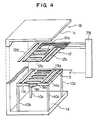
- FIG. 4 and 5 only an upper fixed electrode 12 corresponding to the first electrode body in the embodiment shown in Figs. 1 to 3 is provided for the fixed electrode, in order to facilitate the actuator to easily be assembled and processed.
- a plane electrode 13a is provided only on the upper surface of a movable electrode 13 corresponding to the second electrode body so as to oppose to plane electrodes 12a, 12b, 12c and 12d of the upper fixed electrode 12.
- the movable electrode 13 is mounted on the upper surface of a movable body holder 11a with an interposed insulating layer 14.
- An optical head 4b is disposed on one side end surface of the movable body holder 11a to interpose an insulator 9a therebetween.
- the movable body holder 11a is secured to an upper surface 1d of the lower portion of a holder 1B by means of support springs 10a, 10b, 10c and 10d made of an elastic material having a characteristic such that a rigidity in the Z direction is relatively high and that in the X and Y axes is lower.
- the movable body holder 11a is not displaced in the Z direction even when a suction force acts between the upper fixed electrode 12 and the movable electrode 13, but the holder moves only on the X-Y plane.
- a control method of drive of the movable electrode in this embodiment is similar to that in the embodiment of Fig.
- Reference numeral 7B is a controller similarly to the embodiment of Fig. 1, which is connected to the respective plane electrodes 12a, 12b, 12c, 12d and 13a.
- both upper fixed electrode 12 and movable electrode 13 comprise a plurality of rectangular electrodes.
- the upper fixed electrode 12 comprises in combination the plane electrodes 12a, 12c having rectangular portions each with a wide width in the X direction and a narrow width in the Y direction and the plane electrodes 12b, 12d having rectangular portions each with a narrow width in the X direction and a wide width in the Y direction, and is secured to a lower surface 1c of the upper portion of the holder 1B.
- the movable electrode 13 opposes to the upper fixed electrode 12 with a spaced short interval therebetween, and is composed of the plane electrode 13a having rectangular portions roughly overlapping the respective plane electrodes 12a, 12b, 12c and 12d.
- Fig. 5 is an illustration of the actuator of Fig. 4 viewed from the top thereof in the Z direction.
- the respective plane electrodes 12a to 12d of the upper fixed electrode 12 in the neutral state are illustrated by a broken line and the plane electrode 13a of the movable electrode 13 is illustrated by a continuous line.
- the respective plane electrodes 12a to 12d of the upper fixed electrode 12 are overlapped by the corresponding rectangular portions of the plane electrode 13a of the opposed movable electrode 13, by half a narrower width of each plane electrode.
- the plane electrodes 12b and 12d are located in the X direction, and portions of the plane electrodes 12b and 12d which are not overlapped by the corresponding rectangular portions of the plane electrode 13a are on the half sides of the plane electrodes 12b and 12d, which sides oppose to each other.
- the plane electrodes 12a and 12c are located in the Y direction and portions of the plane electrodes 12a and 12c which are not overlapped by the corresponding rectangular portions of the plane electrode 13a are on the half sides of the plane electrodes 12a and 12c, which sides oppose to each other.
- the same principle as the embodiment in Fig. 1 is utilized for the purpose of generating not only a attraction force but also a force to laterally displacing the movable electrode by roughly overlapping the opposing fixed electrode and movable electrode so as to move the movable electrode 13 on the X-Y plane.
- the plane electrodes are arranged to include a plurality of long and narrow rectangular postions, for elongating end portions of the electrodes which are effective in generating the lateral force. Accordingly, the actuator according to this second embodiment can generate a larger lateral force owing to the same areas of the plane electrodes as in the first embodiment at a certain voltage.
- the movable electrode is hardly displaced in the Z direction in the embodiment of Fig. 4, an interval between the movable electrode 13 and the upper fixed electrode 12 can be reduced. Thanks to that point, the laterally driving force (driving force in the X and Y axes) is also increased.
- Fig. 7 is a perspective view of an electrostatic two-dimensional actuator which is a third embodiment of the present invention.
- the pair of electrodes 12, 13 of the embodiment shown in Fig. 4 are replaced for a pair of electrodes 15 (15a to 15d) and 16 (16a to 16d) having structures different from those of the electrodes of the embodiment in Fig. 4.
- the fixed electrode 15 comprises driving electrodes 15a, 15b in the Y direction and driving electrodes 15c, 15d in the X direction as shown in Fig. 7, and is secured to the lower surface 1a of the upper portion of a fixture holder 1c.
- the movable electrode 16 is composed of driving electrodes 16a, 16b in the Y direction and driving electrodes 16c, 16d in the X direction, and is secured to the upper surface of a movable body holder 11b via a dielectric 14.
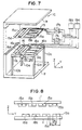
- Fig. 8 illustrates one portion of a cross section of the Y-direction driving electrodes of both fixed and movable electrodes 15, 16 in the vicinity of the center portion of the actuator in the X direction, which cross section is vertical with respect to the X axis.
- the electrodes 16a, 16b of the movable electrode 16 are secured to a movable body holder 14b in parallel with the electrodes 15a, 15b of the fixed electrode 15 secured to the fixture holder 1b, interposing a short interval therebetween.
- the electrodes 15a, 15b of the fixed electrode are adjacent to each other at a distance P1 and similarly, the electrodes 16a, 16b of the movable electrode are adjacent to each other at a distance P1.
- the electrodes 15a, 15b of the fixed electrode are dislocated in the negative direction of the Y axis with respect to the electrodes 16a, 16b of the movable electrode 16.
- the electrodes 15a, 15b, 16a, 16b are located in such a manner that an overlapping amount w1 of any pair of electrodes is maintained constant.
- each pair of adjacent electrodes of the fixed electrode 15 and the movable electrode 16 include different polarities from each other.
- a voltage is applied to the fixed and movable electrodes so that the electrode of the fixed electrode having the same polarity as the corresponding electrode of the movable electrode is positioned in the positive direction with respect to the corresponding movable electrode and the electrode of the fixed electrode having the different polarity from the corresponding electrode of the movable electrode is positioned in the negative direction with respect to the corresponding movable electrode, as viewed from the movable electrode side.
- a suction force acts between the fixed electrode 15a and the movable electrode 16a, and between the fixed electrode 15b and the movable electrode 16b, and a resilient force acts between the electrodes 15b and 16a, and between the electrodes 15a and 16b.
- Both of the suction and resilient forces result in a force for driving the movable electrode 16 in the negative direction of the Y axis.
- a force in the Z direction is effectively decreased because the suction force and the resilient force cancel each other.
- the driving force in the Y direction does not operate.
- the movable electrode 16 further moves to be brought into a dislocated state similar to the state shown in Fig. 8, the movable electrode 16 can be still further moved owing to application of a voltage to the movable and fixed electrodes as in Fig. 8.
- the polarity of the voltage applied to either of the movable or fixed electrode should be inverted.
- a driving circuit is comprised of a voltage control portion 19a and a polarity switching portion 17a. If a voltage having the inverted polarity can be generated by the voltage control portion 19a, the polarity switching portion 17a may be omitted.
- a method for driving the movable electrode in the Y direction has been described so far by way of example, but a driving method of the movable electrode in the X direction is similar to the driving method in the Y direction. Since the configurations of the electrodes in the above-described embodiments are plane-like, it is easy to manufacture a highly precise actuator by adopting the art for manufacturing a semiconductor.
- the present invention is capable of being applied to not only this but also other industrial fields.
- first and third electrode body are fixed and the second electrode body is movable in the respective above-mentioned embodiments.
- the second electrode body may be fixed and the first electrode body may be movable.
Landscapes
- Micromachines (AREA)
- Control Of Position Or Direction (AREA)
Applications Claiming Priority (2)
| Application Number | Priority Date | Filing Date | Title |
|---|---|---|---|
| JP22566/89 | 1989-02-02 | ||
| JP2256689A JPH02206376A (ja) | 1989-02-02 | 1989-02-02 | 静電形多次元アクチュエータ |
Publications (2)
| Publication Number | Publication Date |
|---|---|
| EP0381212A2 true EP0381212A2 (fr) | 1990-08-08 |
| EP0381212A3 EP0381212A3 (fr) | 1991-01-02 |
Family
ID=12086424
Family Applications (1)
| Application Number | Title | Priority Date | Filing Date |
|---|---|---|---|
| EP19900102006 Withdrawn EP0381212A3 (fr) | 1989-02-02 | 1990-02-01 | Actionneur multidimensionnel électrostatique |
Country Status (2)
| Country | Link |
|---|---|
| EP (1) | EP0381212A3 (fr) |
| JP (1) | JPH02206376A (fr) |
Cited By (4)
| Publication number | Priority date | Publication date | Assignee | Title |
|---|---|---|---|---|
| US5958553A (en) * | 1991-03-22 | 1999-09-28 | Teijin Ltd. | Biaxially oriented, polyethylene-2, 6-naphthalate film and magnetic tape formed therefrom |
| EP1202099A3 (fr) * | 2000-10-31 | 2003-04-16 | Kabushiki Kaisha Toshiba | Actionneur électrostatique et module de caméra utilisant l'actionneur |
| WO2003076977A2 (fr) | 2002-03-06 | 2003-09-18 | Glimmerglass Networks, Inc. | Procede et appareil permettant d'actionner un dispositif microelectromecanique biaxial au moyen de trois elements d'actionnement |
| CN113335228A (zh) * | 2020-03-02 | 2021-09-03 | 现代自动车株式会社 | 车辆钥匙及其制造方法 |
Family Cites Families (1)
| Publication number | Priority date | Publication date | Assignee | Title |
|---|---|---|---|---|
| FR2296297A1 (fr) * | 1974-12-27 | 1976-07-23 | Thomson Csf | Dispositif commutateur a commande electrique de deplacement |
-
1989
- 1989-02-02 JP JP2256689A patent/JPH02206376A/ja active Pending
-
1990
- 1990-02-01 EP EP19900102006 patent/EP0381212A3/fr not_active Withdrawn
Cited By (10)
| Publication number | Priority date | Publication date | Assignee | Title |
|---|---|---|---|---|
| US5958553A (en) * | 1991-03-22 | 1999-09-28 | Teijin Ltd. | Biaxially oriented, polyethylene-2, 6-naphthalate film and magnetic tape formed therefrom |
| EP1202099A3 (fr) * | 2000-10-31 | 2003-04-16 | Kabushiki Kaisha Toshiba | Actionneur électrostatique et module de caméra utilisant l'actionneur |
| US6611079B2 (en) | 2000-10-31 | 2003-08-26 | Kabushiki Kaisha Toshiba | Electrostatic actuator and camera module using the same |
| US6717326B2 (en) | 2000-10-31 | 2004-04-06 | Kabushiki Kaisha Toshiba | Electrostatic actuator and camera module using the same |
| WO2003076977A2 (fr) | 2002-03-06 | 2003-09-18 | Glimmerglass Networks, Inc. | Procede et appareil permettant d'actionner un dispositif microelectromecanique biaxial au moyen de trois elements d'actionnement |
| US6717325B2 (en) * | 2002-03-06 | 2004-04-06 | Glimmerglass Networks, Inc. | Method and apparatus for actuation of a two-axis MEMS device using three actuation elements |
| EP1488500A4 (fr) * | 2002-03-06 | 2010-04-21 | Glimmerglass Networks Inc | Procede et appareil permettant d'actionner un dispositif microelectromecanique biaxial au moyen de trois elements d'actionnement |
| CN105068561A (zh) * | 2002-03-06 | 2015-11-18 | 格雷姆格拉斯网络公司 | 利用三个驱动元件驱动双轴mems器件的方法和装置 |
| CN105068561B (zh) * | 2002-03-06 | 2018-01-23 | 格雷姆格拉斯网络公司 | 利用三个驱动元件驱动双轴mems器件的方法和装置 |
| CN113335228A (zh) * | 2020-03-02 | 2021-09-03 | 现代自动车株式会社 | 车辆钥匙及其制造方法 |
Also Published As
| Publication number | Publication date |
|---|---|
| EP0381212A3 (fr) | 1991-01-02 |
| JPH02206376A (ja) | 1990-08-16 |
Similar Documents
| Publication | Publication Date | Title |
|---|---|---|
| JPH05219760A (ja) | 静電式アクチュエータ | |
| US7705514B2 (en) | Bi-directional actuator utilizing both attractive and repulsive electrostatic forces | |
| MXPA04009942A (es) | Motor electrico. | |
| US6933662B2 (en) | Electrostrictive compound actuator | |
| JP3964612B2 (ja) | 静電アクチュエータ | |
| JP2003092890A (ja) | 静電アクチュエータ、静電アクチュエータの駆動方法及びこれを用いたカメラモジュール | |
| EP0381212A2 (fr) | Actionneur multidimensionnel électrostatique | |
| JP2000011556A (ja) | マイクロアクチュエータ及び磁気ヘッド装置並びに磁気記録装置 | |
| US6046527A (en) | Ultrasonic positioner with multiple degrees of freedom of movement | |
| JP2928752B2 (ja) | 静電アクチュエータ及びその駆動方法 | |
| JP4102343B2 (ja) | 大面積ステージを備えた2軸アクチュエータ | |
| US20080224565A1 (en) | Electrostatic actuator | |
| JP2839526B2 (ja) | 静電形アクチュエータ | |
| JP2007259691A (ja) | Memsの静電駆動法、静電アクチュエーター、及びマイクロスイッチ | |
| JPH0576187A (ja) | 静電アクチユエータ | |
| KR100254394B1 (ko) | 초소형 마이크로 로봇 및 그 구동방법 | |
| JP2850413B2 (ja) | 静電アクチュエータ | |
| JP2003209027A (ja) | 微細加工バラクター | |
| JPH08116686A (ja) | 静電式リニアアクチュエータ | |
| JPH02239432A (ja) | 静電形多次元アクチュエータ | |
| KR100263750B1 (ko) | 선택적 전압인가에 의한 양방향 제어의 빗살형 일렉트로스테틱마이크로 액츄에이터 | |
| JP3475443B2 (ja) | 静電アクチュエータ | |
| CA2485153C (fr) | Declencheur bidirectionnel utilisant des forces electrostatiques d'attraction et de repulsion | |
| JP3021460B2 (ja) | 静電アクチュエータ | |
| JPH0947042A (ja) | 静電アクチュエータ |
Legal Events
| Date | Code | Title | Description |
|---|---|---|---|
| PUAI | Public reference made under article 153(3) epc to a published international application that has entered the european phase |
Free format text: ORIGINAL CODE: 0009012 |
|
| AK | Designated contracting states |
Kind code of ref document: A2 Designated state(s): DE FR |
|
| PUAL | Search report despatched |
Free format text: ORIGINAL CODE: 0009013 |
|
| RHK1 | Main classification (correction) |
Ipc: H02N 1/00 |
|
| AK | Designated contracting states |
Kind code of ref document: A3 Designated state(s): DE FR |
|
| 17P | Request for examination filed |
Effective date: 19901127 |
|
| 17Q | First examination report despatched |
Effective date: 19921111 |
|
| STAA | Information on the status of an ep patent application or granted ep patent |
Free format text: STATUS: THE APPLICATION HAS BEEN WITHDRAWN |
|
| 18W | Application withdrawn |
Withdrawal date: 19930311 |