EP0381878A1 - Verfahren und Gerät zur Diagnose von Netzwerken - Google Patents
Verfahren und Gerät zur Diagnose von Netzwerken Download PDFInfo
- Publication number
- EP0381878A1 EP0381878A1 EP89301198A EP89301198A EP0381878A1 EP 0381878 A1 EP0381878 A1 EP 0381878A1 EP 89301198 A EP89301198 A EP 89301198A EP 89301198 A EP89301198 A EP 89301198A EP 0381878 A1 EP0381878 A1 EP 0381878A1
- Authority
- EP
- European Patent Office
- Prior art keywords
- packet
- echo
- bus
- network
- timer
- Prior art date
- Legal status (The legal status is an assumption and is not a legal conclusion. Google has not performed a legal analysis and makes no representation as to the accuracy of the status listed.)
- Granted
Links
- 238000000034 method Methods 0.000 title claims description 9
- 238000003745 diagnosis Methods 0.000 title 1
- 238000005259 measurement Methods 0.000 claims description 12
- 230000005540 biological transmission Effects 0.000 claims description 8
- 230000001902 propagating effect Effects 0.000 claims description 8
- 230000000875 corresponding effect Effects 0.000 claims description 7
- 238000004891 communication Methods 0.000 claims description 6
- 238000003860 storage Methods 0.000 claims description 6
- 238000001514 detection method Methods 0.000 claims description 2
- 238000010586 diagram Methods 0.000 description 3
- 238000012935 Averaging Methods 0.000 description 2
- 239000013078 crystal Substances 0.000 description 2
- 230000000694 effects Effects 0.000 description 2
- 238000011835 investigation Methods 0.000 description 2
- 238000013459 approach Methods 0.000 description 1
- 230000000977 initiatory effect Effects 0.000 description 1
- 230000014759 maintenance of location Effects 0.000 description 1
- 238000013507 mapping Methods 0.000 description 1
- 238000005065 mining Methods 0.000 description 1
- 238000012544 monitoring process Methods 0.000 description 1
- 238000012546 transfer Methods 0.000 description 1
Images


Classifications
-
- H—ELECTRICITY
- H04—ELECTRIC COMMUNICATION TECHNIQUE
- H04L—TRANSMISSION OF DIGITAL INFORMATION, e.g. TELEGRAPHIC COMMUNICATION
- H04L43/00—Arrangements for monitoring or testing data switching networks
- H04L43/50—Testing arrangements
Definitions
- the present invention relates to a network diagnostic tool and relates particularly, but not exclusively, to a diagnostic tool for mapping the position of network nodes on a local area network (LAN).
- LAN local area network
- a network diagnostic tool for use in determining the position of a network node along a bus, wherein packets from the network node propagate in both directions along the bus, characterised by means for measuring the time difference between the arrival at predetermined locations of corresponding packets which have travelled in opposite directions along the bus.
- the predetermined locations are at the two ends of the bus.
- the invention may be embodied by attaching a connection to each end of the LAN and monitoring the time at which a packet arrives at each of the ends. However, in this case a connection is made to each end of the LAN and the delay in the connections themselves must be measured and allowed for in subsequent measurements.
- a network diagnostic tool for use in determining the position of a network node along a bus wherein packets from the network node propagate in both directions along the bus, characterised by timer means for receiving a packet sent from the network node and propagating in one direction along the bus, echo means for receiving the corresponding packet propagating in the opposite direction along the bus and for subsequently sending an echo packet to the timer means and means for calculating the time delay between the arrival of the packet and the echo packet at the timer means.
- the timer means and echo means comprise means for detecting packet arrival times and for identifying the source address of arriving packets.
- the echo means preferably comprises means for detecting the transmission time of a packet relative to its arrival time.
- the timer means and echo means may comprise the same hardware components and may each be embodied on computer card.
- a method for determining the position of a network node on a communications network comprising a bus to which the network node is connected and timer means and echo means connected at opposed ends of the bus, characterised by the steps of: sending a packet from the network node onto the bus so that the packet propagates in both directions along the bus; receiving the packet propagating in one direction at the timer means; receiving the packet propagating in the opposite direction at the echo means and subsequently sending an echo packet in said one direction; receiving the echo packet at the timer means; determining the time delay between receipt of the packet and the echo packet at the timer means.
- the method may further comprise sending a packet containing echo time information from the echo means to the timer means.
- the method may comprise initially sending a packet between the timer means and the echo means identifying the network address of the network node.
- the network diagnostic tool comprises packet detecting means connected to a first end of the bus and timer means connected to a second end of the bus wherein the timer means is capable of packet detection and means for transmitting a signal from the packet detecting means to the timer means indicating receipt of a packet by the packet detecting means.
- the timer means is operable to calculate the time difference between the arrival of a packet from the second end of the bus and the arrival of a signal indicating receipt of a packet by the packet detecting means.
- the timer means comprises first storage means for storing the time of arrival of a signal indicative of the receipt of a packet by the packet detecting means and second storage means for storing the time of arrival of a packet from the second end of the bus.
- the timer means comprises a microprocessor system for utilising the values stored in the first and second storage means to calculate the position of the network node along the bus.
- Embodiments of the invention will be described with regard to the IEEE 802.3 network by way of example and it should be understood that the invention is also applicable to other types of network.
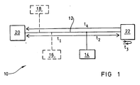
- Figure 1 shows a LAN indicated generally at 10 comprising a shared multi-access bus 12 and several workstations 14, 16, 18, 20 and 22.
- the workstations 20 and 22 are connected to the ends of the bus 12 and also function as timer and echo stations respectively.
- the workstation 14 represents the network node whose position is to be determined and the remaining workstations are shown in dotted lines.
- the diagnostic tool operates as follows:
- timer station 20 and echo station 22 Communication between the timer station 20 and echo station 22 is needed in order to synchronise activity eg. as to which is the workstation under investigation. Therefore, a communications protocol is required between the timer and echo stations 20 and 22.
- Both the timer and echo stations may be computers with special purpose LAN interfaces which also allow the LAN to be used for normal communication.
- the timer and echo stations 20 and 22 comprise special purpose time consistent matching hardware for identifying packets and for enabling packet transmission after a measured delay.
- the 'time consistent matching hardware' is meant that the time taken to detect the arrival of a packet is the same for both sets of hardware and that the echo time can be measured consistently. Since the packet matching and timing functions are common to the timer and echo stations 20 and 22, a common interface card could be designed which performs all the necessary functions of the timer and echo stations.
- the timer means in the timer station 20 is indicated generally at 30.
- the timer means 30 comprises a microprocessor system and network controller 32, a transmit time register 34, a receive time register 36, a counter 38 and an oscillator 40.
- the timer means 30 communicates with the LAN 10 by means of a network transceiver 42, such as a standard IEEE 802.3 transceiver.
- Incoming signals are supplied from the transceiver 42 to the microprocessor system 32 via a data receive amplifier and filter 44 and a line decoder 46, such as a Manchester decoder.
- Incoming signals are supplied from the network transceiver 42 to the receive time register 36 via a carrier or packet detect device 48.
- Signals are supplied from the microprocessor 32 to the network transceiver 42 via a line encoder 50, such as a Manchester encoder, and a transmitter amplifier 52.
- the echo means in the echo station 22 comprises the same components as the timer means 30. Both the timer means 30 and the echo means may form part of a computer card. It will be understood that the timer means will not make use of the transmit time register 34. The "write" signals to the transmit time and receive time registers 34 and 36 must be generated accurately at the point of packet transmission and reception respectively.
- timer and echo stations 20 and 22 implement the algorithms described as follows and as illustrated in Figure 3:
- the system is arranged so that the packet matching functions are carried out without tight time constraints.
- the network diagnostic tool may be configured so as to echo all packets received, or all packets received within a selected time period, rather than only to echo packets from the chosen workstation.
- the timing resolution necessary in the timer means 30 depends upon the speed of propagation on the network and the required accuracy of network node position resolution along the bus.
- the propagation speed is approximately 0.2 metres per nanosecond.
- the minimum recommended distance between any two stations is 2.5 metres.
- the counter 38 In order to provide this timing resolution the counter 38 is required to operate at a frequency equal to or greater than 40 megahertz. To provide the necessary accuracy the counter must be accurate to greater than 25 ns over the complete interval timed.
- the minimum packet length on an IEEE 802.3 network is 596 bits and the transmission rate is 10 Mbits/s.
- the algorithm requires that a time interval equivalent to the transmission time of a minimum size packet plus upto twice the end to end propagation delay plus the time delay between packet receipt and packet transmission at the echo station be measured.
- the above embodiment provides a network diagnostic tool for ascertaining the position of a network node along a multi-access bus without the need for any external connections to the network.
- FIG. 4 shows a LAN 100 comprising a multi-access bus 102 and network nodes 104 and 106. Packets from the network nodes travel in both directions along the multi-access bus 102.
- a packet detect device 108 is connected to the first end of the bus 102 and a timer device in the form of a special purpose network node 110 is connected to the other end of the bus 102.
- a cable 112 interconnects the packet detect device 108 and the special purpose network node 110.
- the network diagnostic tool depicted in Figure 4 operates as follows.
- T1 time of arrival
- T2 time of arrival
- V is the propagation speed on the network.
- the sign of x indicates with respect to which end of the bus 102 the calculated distance is to be used.
- the packet detect device 108 comprises a network receiver 114, a packet detector 116 and a signal transmitter 118.
- the special purpose network node 110 comprises a microprocessor system 120 which receives timing data from two receive time registers 122 and 124.
- An oscillator 126 provides clock signals to a counter 128 which is connected to the registers 122 and 124.
- a signal detector 130 detects signals sent from the signal transmitter 118 via the cable 112.
- a network receiver 132 receives packets from the bus 102 and sends these to a packet detector 134 connected to the register 124 and also to an amplifier and filter 136.
- the amplifier and filter 136 is connected to a line decoder 138 which supplies signals to the microprocessor system 120.
- a packet emitted from the network node 104 is received by the network receiver 114 which supplies signals to the packet detector 116 which provides a signal pulse which is amplified by the signal transmitter 118 to produce a signal which indicates the arrival of a packet.
- This signal travels via the cable 112 to the signal detector 130 of the special purpose network node 110 which causes the register 122 to latch the value of the counter 128.
- the corresponding packet arriving at the second end of the bus 102 is transferred via the network receiver 132 to the packet detector 134 which produces a signal causing the register 124 to latch the value of the counter 128.
- the amplifier and filter 136 transfer signals from the network receiver 132 to the microprocessor system 120 via the line decoder 138 where the transmitted packet data will be recovered.
- the microprocessor system 120 identifies the network node source address supplied in the data packet and reads the contents of the registers 122 and 124 after a delay which is longer than the network propagation delay. In effect the microprocessor is alerted to the arrival of a packet at the second end of the bus 102 soon after the packet begins to arrive and then waits for the contents of the registers 122 and 124 to change.
- V is the propagation speed on the network and t p and t q are as explained above.
- the sign of the result indicates whether the calculated distance is with respect to the first or the second end of the bus 102.
- the time taken to transmit or receive a packet is much greater than the propagation time along the network. This means that there is no real chance of spurious measurements being made as a result of confusion between different packets sent by a single network node.
- measurement accuracy and reliability may be improved by taking multiple readings and averaging these.
Landscapes
- Engineering & Computer Science (AREA)
- Computer Networks & Wireless Communication (AREA)
- Signal Processing (AREA)
- Small-Scale Networks (AREA)
- Data Exchanges In Wide-Area Networks (AREA)
Priority Applications (3)
| Application Number | Priority Date | Filing Date | Title |
|---|---|---|---|
| DE68919674T DE68919674T2 (de) | 1989-02-08 | 1989-02-08 | Verfahren und Gerät zur Diagnose von Netzwerken. |
| EP89301198A EP0381878B1 (de) | 1989-02-08 | 1989-02-08 | Verfahren und Gerät zur Diagnose von Netzwerken |
| US07/475,694 US5226036A (en) | 1989-02-08 | 1990-02-06 | Network diagnostic tool |
Applications Claiming Priority (1)
| Application Number | Priority Date | Filing Date | Title |
|---|---|---|---|
| EP89301198A EP0381878B1 (de) | 1989-02-08 | 1989-02-08 | Verfahren und Gerät zur Diagnose von Netzwerken |
Publications (2)
| Publication Number | Publication Date |
|---|---|
| EP0381878A1 true EP0381878A1 (de) | 1990-08-16 |
| EP0381878B1 EP0381878B1 (de) | 1994-11-30 |
Family
ID=8202586
Family Applications (1)
| Application Number | Title | Priority Date | Filing Date |
|---|---|---|---|
| EP89301198A Expired - Lifetime EP0381878B1 (de) | 1989-02-08 | 1989-02-08 | Verfahren und Gerät zur Diagnose von Netzwerken |
Country Status (3)
| Country | Link |
|---|---|
| US (1) | US5226036A (de) |
| EP (1) | EP0381878B1 (de) |
| DE (1) | DE68919674T2 (de) |
Cited By (4)
| Publication number | Priority date | Publication date | Assignee | Title |
|---|---|---|---|---|
| EP0474380A1 (de) * | 1990-09-04 | 1992-03-11 | Hewlett-Packard Company | Verfahren und Gerät zur Überwachung eines Netzes |
| EP0474378A1 (de) * | 1990-09-04 | 1992-03-11 | Hewlett-Packard Company | Verfahren und Gerät zur Kollisionsüberwachung in einem Netz |
| US5198805A (en) * | 1990-09-04 | 1993-03-30 | Hewlett-Packard Company | Method and apparatus for monitoring a network and locating a node using signal strength calculations |
| US6804624B2 (en) | 2001-08-31 | 2004-10-12 | International Business Machines Corporation | System and method for determining the location of remote devices |
Families Citing this family (8)
| Publication number | Priority date | Publication date | Assignee | Title |
|---|---|---|---|---|
| US5815344A (en) | 1992-02-17 | 1998-09-29 | Sony Corporation | Disc cartridge loading apparatus |
| JP3720364B2 (ja) * | 1994-09-12 | 2005-11-24 | 日立電子サービス株式会社 | Lanシステムの物理的構成情報を採取する方法、衝突端末の特定方法およびノイズ発生位置検出方法 |
| US5706440A (en) * | 1995-08-23 | 1998-01-06 | International Business Machines Corporation | Method and system for determining hub topology of an ethernet LAN segment |
| WO1997027685A2 (en) * | 1996-01-29 | 1997-07-31 | Lecroy Corporation | Packet network monitoring device |
| DE19710971A1 (de) * | 1997-03-17 | 1998-09-24 | Siemens Ag | Verfahren zur Bestimmung der Laufzeit eines Telegramms sowie Teilnehmer zur Durchführung des Verfahrens |
| KR20040094437A (ko) * | 2002-03-12 | 2004-11-09 | 코닌클리케 필립스 일렉트로닉스 엔.브이. | 두 개의 노드들 사이의 프록시미티를 결정하기 위한타이밍 신호들의 사용 |
| AU2003293164A1 (en) * | 2002-11-27 | 2004-06-23 | U-Nav Microelectronics Corporation | System and method for networking a plurality of nodes |
| US8149168B1 (en) * | 2006-01-17 | 2012-04-03 | Trueposition, Inc. | Position determination using wireless local area network signals and television signals |
Citations (1)
| Publication number | Priority date | Publication date | Assignee | Title |
|---|---|---|---|---|
| US4766549A (en) * | 1984-11-30 | 1988-08-23 | Electric Power Research Institute, Inc. | Single-ended transmission line fault locator |
Family Cites Families (11)
| Publication number | Priority date | Publication date | Assignee | Title |
|---|---|---|---|---|
| US3953856A (en) * | 1961-02-02 | 1976-04-27 | Hammack Calvin M | Method and apparatus for mapping and similar applications |
| GB1396821A (en) * | 1973-03-22 | 1975-06-04 | Elliott Brothers London Ltd | Ranging systems |
| US4297701A (en) * | 1979-08-08 | 1981-10-27 | John D. Angleman | Rangefinder using expanded time delay |
| JPS5954347A (ja) * | 1982-09-22 | 1984-03-29 | Fujitsu Ltd | チヤネル插入タイミング調整方式 |
| DE3464185D1 (en) * | 1983-03-31 | 1987-07-16 | Toshiba Kk | Bus-configured local area network with data exchange capability |
| JPS61145995A (ja) * | 1984-12-20 | 1986-07-03 | Toshiba Corp | 集線分配装置 |
| JPS61169047A (ja) * | 1985-01-22 | 1986-07-30 | Kokusai Denshin Denwa Co Ltd <Kdd> | 光フアイバ伝送路の伝搬遅延時間変動量検出方式 |
| US4750036A (en) * | 1986-05-14 | 1988-06-07 | Radio Telcom & Technology, Inc. | Interactive television and data transmission system |
| JPS6466582A (en) * | 1987-09-08 | 1989-03-13 | Nec Corp | System for detecting propagation time of transmission line |
| US5048009A (en) * | 1989-02-28 | 1991-09-10 | Hewlett-Packard Company | Broadcast station locator for a local area network |
| US4947425A (en) * | 1989-10-27 | 1990-08-07 | At&T Bell Laboratories | Echo measurement arrangement |
-
1989
- 1989-02-08 EP EP89301198A patent/EP0381878B1/de not_active Expired - Lifetime
- 1989-02-08 DE DE68919674T patent/DE68919674T2/de not_active Expired - Fee Related
-
1990
- 1990-02-06 US US07/475,694 patent/US5226036A/en not_active Expired - Lifetime
Patent Citations (1)
| Publication number | Priority date | Publication date | Assignee | Title |
|---|---|---|---|---|
| US4766549A (en) * | 1984-11-30 | 1988-08-23 | Electric Power Research Institute, Inc. | Single-ended transmission line fault locator |
Non-Patent Citations (2)
| Title |
|---|
| MILCOM '87, IEEE MILITARY COMMUNICATIONS CONFERENCE, Washington, D.C., 19th-22nd October 1987, vol. 2, pages 370-376, IEEE, New York, US; P. SEVCIK et al.: "Neptune performance measurement concept and tool" * |
| PATENT ABSTRACTS OF JAPAN, vol. 9, no. 110 (E-314)[1833], 15th May 1985; & JP-A-60 001 950 (MATSUSHITA DENKI SANGYO K.K.) 08-01-1985 * |
Cited By (4)
| Publication number | Priority date | Publication date | Assignee | Title |
|---|---|---|---|---|
| EP0474380A1 (de) * | 1990-09-04 | 1992-03-11 | Hewlett-Packard Company | Verfahren und Gerät zur Überwachung eines Netzes |
| EP0474378A1 (de) * | 1990-09-04 | 1992-03-11 | Hewlett-Packard Company | Verfahren und Gerät zur Kollisionsüberwachung in einem Netz |
| US5198805A (en) * | 1990-09-04 | 1993-03-30 | Hewlett-Packard Company | Method and apparatus for monitoring a network and locating a node using signal strength calculations |
| US6804624B2 (en) | 2001-08-31 | 2004-10-12 | International Business Machines Corporation | System and method for determining the location of remote devices |
Also Published As
| Publication number | Publication date |
|---|---|
| DE68919674T2 (de) | 1995-04-06 |
| EP0381878B1 (de) | 1994-11-30 |
| DE68919674D1 (de) | 1995-01-12 |
| US5226036A (en) | 1993-07-06 |
Similar Documents
| Publication | Publication Date | Title |
|---|---|---|
| US7602873B2 (en) | Correcting time synchronization inaccuracy caused by asymmetric delay on a communication link | |
| EP0381878B1 (de) | Verfahren und Gerät zur Diagnose von Netzwerken | |
| EP0146566B1 (de) | Schema zur verringerung der übertragungsverzögerung nach kollisionen in nachrichtennetzen | |
| US6122257A (en) | Method for collecting information about physical constitution of lan system, method of specifying collision terminals, and method for detecting noise-generated position | |
| JP2001168882A (ja) | 地震装置の要素を伝送チャネルにより一緒に接続する伝送方法および伝送システム | |
| JPH08511623A (ja) | 物体の、超音波送受波ユニットからの距離を測定するための方法および装置 | |
| JPH11133097A (ja) | 母線系統における短絡又はケーブル破断の位置確認方法及び回路装置 | |
| US20240171471A1 (en) | Topology discovery in multidrop ethernet nodes | |
| JP2659797B2 (ja) | Lanにおける故障箇所検出装置 | |
| JP2546370B2 (ja) | パケット伝達特性測定方法 | |
| EP1669879B1 (de) | Verfahren, System und Vorrichtung für die Verwaltung der Verbindungsverzögerung | |
| JPH02176588A (ja) | 距離測定器 | |
| JPH065253B2 (ja) | ケ−ブル線路の事故点標定法 | |
| JPH02196985A (ja) | 超音波式距離測定装置 | |
| JP2641643B2 (ja) | Ssbl方式による水中位置測定方法 | |
| JPS6333685A (ja) | 超音波物体検知器 | |
| JPH032434B2 (de) | ||
| EP0132645A2 (de) | Verfahren und Vorrichtung zur Erleichterung der Kollisionserkennung | |
| JPH08271628A (ja) | 超音波測距システム | |
| JPS61215970A (ja) | ケ−ブル線路の事故点標定法 | |
| US7053818B1 (en) | Method for simple and multipurpose tracking | |
| JPH04229754A (ja) | 変復調装置 | |
| JPH09121221A (ja) | データ送受信装置 | |
| SU1205797A1 (ru) | Устройство дл контрол высева | |
| CA2107198A1 (en) | Method and apparatus for accurate acoustic distance measurement |
Legal Events
| Date | Code | Title | Description |
|---|---|---|---|
| PUAI | Public reference made under article 153(3) epc to a published international application that has entered the european phase |
Free format text: ORIGINAL CODE: 0009012 |
|
| AK | Designated contracting states |
Kind code of ref document: A1 Designated state(s): DE FR GB IT |
|
| 17P | Request for examination filed |
Effective date: 19901023 |
|
| 17Q | First examination report despatched |
Effective date: 19930318 |
|
| GRAA | (expected) grant |
Free format text: ORIGINAL CODE: 0009210 |
|
| AK | Designated contracting states |
Kind code of ref document: B1 Designated state(s): DE FR GB IT |
|
| PG25 | Lapsed in a contracting state [announced via postgrant information from national office to epo] |
Ref country code: IT Free format text: LAPSE BECAUSE OF FAILURE TO SUBMIT A TRANSLATION OF THE DESCRIPTION OR TO PAY THE FEE WITHIN THE PRE;WARNING: LAPSES OF ITALIAN PATENTS WITH EFFECTIVE DATE BEFORE 2007 MAY HAVE OCCURRED AT ANY TIME BEFORE 2007. THE CORRECT EFFECTIVE DATE MAY BE DIFFERENT FROM THE ONE RECORDED.SCRIBED TIME-LIMIT Effective date: 19941130 |
|
| REF | Corresponds to: |
Ref document number: 68919674 Country of ref document: DE Date of ref document: 19950112 |
|
| ET | Fr: translation filed | ||
| PLBE | No opposition filed within time limit |
Free format text: ORIGINAL CODE: 0009261 |
|
| STAA | Information on the status of an ep patent application or granted ep patent |
Free format text: STATUS: NO OPPOSITION FILED WITHIN TIME LIMIT |
|
| 26N | No opposition filed | ||
| PGFP | Annual fee paid to national office [announced via postgrant information from national office to epo] |
Ref country code: FR Payment date: 19980121 Year of fee payment: 10 |
|
| PGFP | Annual fee paid to national office [announced via postgrant information from national office to epo] |
Ref country code: DE Payment date: 19980123 Year of fee payment: 10 |
|
| PGFP | Annual fee paid to national office [announced via postgrant information from national office to epo] |
Ref country code: GB Payment date: 19980127 Year of fee payment: 10 |
|
| PG25 | Lapsed in a contracting state [announced via postgrant information from national office to epo] |
Ref country code: GB Free format text: LAPSE BECAUSE OF NON-PAYMENT OF DUE FEES Effective date: 19990208 |
|
| GBPC | Gb: european patent ceased through non-payment of renewal fee |
Effective date: 19990208 |
|
| PG25 | Lapsed in a contracting state [announced via postgrant information from national office to epo] |
Ref country code: FR Free format text: LAPSE BECAUSE OF NON-PAYMENT OF DUE FEES Effective date: 19991029 |
|
| PG25 | Lapsed in a contracting state [announced via postgrant information from national office to epo] |
Ref country code: DE Free format text: LAPSE BECAUSE OF NON-PAYMENT OF DUE FEES Effective date: 19991201 |
|
| REG | Reference to a national code |
Ref country code: FR Ref legal event code: ST |