EP0385774A2 - Méthode et appareil de protection contre les coupures dans l'alimentation - Google Patents
Méthode et appareil de protection contre les coupures dans l'alimentation Download PDFInfo
- Publication number
- EP0385774A2 EP0385774A2 EP90302184A EP90302184A EP0385774A2 EP 0385774 A2 EP0385774 A2 EP 0385774A2 EP 90302184 A EP90302184 A EP 90302184A EP 90302184 A EP90302184 A EP 90302184A EP 0385774 A2 EP0385774 A2 EP 0385774A2
- Authority
- EP
- European Patent Office
- Prior art keywords
- power
- data processing
- power supply
- processing apparatus
- standby power
- Prior art date
- Legal status (The legal status is an assumption and is not a legal conclusion. Google has not performed a legal analysis and makes no representation as to the accuracy of the status listed.)
- Granted
Links
Images


Classifications
-
- G—PHYSICS
- G06—COMPUTING OR CALCULATING; COUNTING
- G06F—ELECTRIC DIGITAL DATA PROCESSING
- G06F1/00—Details not covered by groups G06F3/00 - G06F13/00 and G06F21/00
- G06F1/26—Power supply means, e.g. regulation thereof
- G06F1/30—Means for acting in the event of power-supply failure or interruption, e.g. power-supply fluctuations
-
- G—PHYSICS
- G06—COMPUTING OR CALCULATING; COUNTING
- G06F—ELECTRIC DIGITAL DATA PROCESSING
- G06F11/00—Error detection; Error correction; Monitoring
- G06F11/07—Responding to the occurrence of a fault, e.g. fault tolerance
- G06F11/16—Error detection or correction of the data by redundancy in hardware
- G06F11/20—Error detection or correction of the data by redundancy in hardware using active fault-masking, e.g. by switching out faulty elements or by switching in spare elements
- G06F11/2015—Redundant power supplies
-
- G—PHYSICS
- G06—COMPUTING OR CALCULATING; COUNTING
- G06F—ELECTRIC DIGITAL DATA PROCESSING
- G06F11/00—Error detection; Error correction; Monitoring
- G06F11/07—Responding to the occurrence of a fault, e.g. fault tolerance
- G06F11/0703—Error or fault processing not based on redundancy, i.e. by taking additional measures to deal with the error or fault not making use of redundancy in operation, in hardware, or in data representation
- G06F11/0751—Error or fault detection not based on redundancy
- G06F11/0754—Error or fault detection not based on redundancy by exceeding limits
- G06F11/0757—Error or fault detection not based on redundancy by exceeding limits by exceeding a time limit, i.e. time-out, e.g. watchdogs
Definitions
- This invention relates to data processing apparatus and to a method for power failure protection of data processing apparatus.
- a method for the power failure protection of a data processing apparatus having a normal power supply and a standby power supply associated therewith characterized by the following steps: setting a timer in the data processing apparatus to a value equal to a period of time during which the standby power supply is capable of supplying power to said data processing system when said standby power supply is fully charged; repetitively checking the status of the standby power supply to determine whether or not said standby power supply is supplying power to said data processing apparatus in place of the normal power supply when said normal power supply is interrupted; starting operation of said timer when said standby power supply is found, during said repetitive checking, to be supplying power to said data processing apparatus; continuing to repetitively check the status of said standby power supply and stopping and starting the operation of said timer in accordance with the operation of said timer in accordance with the termination and any subsequent commencement of the supplying of power to said data processing apparatus by said standby power supply until the time remaining on said timer is exhausted; and shutting down the operation
- a data processing system including data processing means which includes logic and control circuitry and memory means adapted to store: operation system software for controlling the logic and control circuitry to enable said data processing means to perform various functions; and application software for causing the data processing means to perform specific routines, characterized in that said memory means is further adapted to store power failure protection software; in that said data processing means further includes a timer associated with said power failure protection software for timing the duration of events associated with said data processing means; and in that said system further includes: a source of power for normally operating said data processing means; standby power means coupled to said source of power and to said data processing means for supplying power from said source of power to said data processing means, said standby power means also including auxiliary power means for supplying standby power to said data processing means in the event of loss of power from said source of power, means to recharge said auxiliary power means from said source of power, monitoring means to monitor any failure of power from said source of power and to initiate use of said auxiliary power means to supply power in the event of failure
- a method and system according to the invention have the advantage of providing for orderly system shut-down before failure of the standby power supply, thus preventing loss of data or files which might otherwise occur.
- a data processing apparatus 20 includes application software 22, other software 24 which may include operating system software, and power failure protection software 26. All of the software is stored in one or more memory devices included in the data processing apparatus 20.
- the data processing apparatus includes a timer 28.
- Other devices such as logic and control circuitry, are also included in the data processing apparatus in order to enable it to carry out various operations in accordance with the software associated with it. However, these other devices are conventional and function in the normal operation of the data processing apparatus, so that it is not believed to be necessary to show or describe them specifically.
- the present invention may be embodied in an arrangement which includes any conventional type of data processing apparatus 20, one such type being the NCR 7003, manufactured by NCR Corporation, Dayton, Ohio.
- the power is supplied to the data processing apparatus 20 through a cable 30.
- the power is in the form of 120 volts AC, but the invention is not so limited and is applicable to other power sources.
- the power is supplied to the data processing apparatus 20 from a standby power module 32, which in turn obtains the power through a cable 34 which may be plugged into a standard power receptacle, such as a wall outlet.
- Any suitable standby power module 32 may be employed.
- One such module is commercially available as model no. 998-062-7302 from NCR Corporation, Dayton, Ohio. It includes rechargeable batteries 35 to supply power to the data processing apparatus 20 in the absence of the normal power supply, circuitry 36 to monitor power failure and to enable battery recharging from the normal power source when the batteries become depleted, and after normal power has resumed, and a switch 38 settable by the hardware 36 to provide information to the data processing apparatus 20 concerning whether or not the standby power module 32 is coupled to the data processing apparatus 20 and, if so, whether or not it is supplying standby battery power to the data processing apparatus 20.
- the switch 38 is connected to the data processing apparatus 20 through a suitable connector 40, which may, for example, be a 9 pin D shell connector or a Centronics D connector.
- the standby power module 32 continuously monitors the normal power supply and automatically commences to provide power from its batteries to the data processing apparatus 20 in the event of a failure of the normal power supply.
- Fig. 2 shows the switch 38 in somewhat greater detail. Any suitable form of electronic or mechanical switch may be used. As shown in Fig. 2, the switch is of the single pole, double throw type having a blade 42 which is movable under control of the circuitry 36 between a first position in which it engages a terminal 44 and a second position in which it engages a terminal 46.
- the connector 40 may be considered to have three conductive elements or paths, represented in Fig. 2 by the designations ring, tip and sleeve, with the ring being connected to the blade 42 of the switch 38, the sleeve being connected to the terminal 44 and the tip being connected to the terminal 46.
- Figs. 3 and 4 show truth tables for the switch 38 with two illustrated types of connectors 40.
- Fig. 3 is applicable when a 9 pin D shell connector is used
- Fig. 4 is applicable when a Centronics D shell connector is used. It will be noted that the voltage levels are reversed as to significance between the two types of connectors, due to their structure, so that the manner of operation of the switch 38 by the circuitry 36 must be selected in accordance with the type of connector 40 which is used.
- a low logic level on the sleeve of the connector 40 (associated with pin 6 of the connection of the connector 40 to the data processing apparatus 20) combined with a high logic level on the tip of the connector 40 (associated with pin 8) provides an indication to the data processing apparatus 20 that the standby power module 32 is connected to the data processing apparatus 20 and is currently supplying battery power to said apparatus.
- a high logic level on the sleeve of the connector 40 combined with a low logic level on the tip of the connector 40 provides an indication that the standby power module 32 is connected to the data processing apparatus 20, but is not currently supplying battery power to said apparatus; in other words, the normal power supply is functioning properly.
- low logic levels on both the sleeve and the tip of the connector 40 indicate that the standby power module is not present in the system. Normally in such a case, power would be supplied directly to the data processing apparatus 20 from a 120-volt AC source.
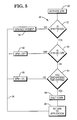
- FIG. 5 Shown in Fig. 5 is a flow diagram of the power failure protection routine 48 which may be utilized in the data processing apparatus 20 to prevent damage to other software contained therein.
- the routine is initiated by a command contained in the application software which is being run to activate the standby power module 32, as represented in the block 50.
- the switch 38 provides information (block 60) to the data processing apparatus 20 as to whether the standby power module 32 is currently on (supplying power to the data processing apparatus because of a power failure of the normal power source) or off (not supplying power because the normal power source is functioning properly), as represented by block 62. If the standby power module 32 is off, the process continues via path 56 to return to the application program (block 58), as previously described.
- the process continues to block 64, in which a determination is made as to whether or not the predetermined discharging time for the standby power module 32 has expired.
- the discharging time is calculated on the basis of providing an assured minimum time during which the standby power module 32 will be capable of providing power to the data processing apparatus 20 with assurance that the power will not be exhausted and thus possibly cause a sudden power failure which could result in damage to the system.
- this minimum time value depends upon a number of factors, such as the predetermined time duration for which the batteries of the standby power module are capable of providing satisfactory power, the number of units, if more than one, which the battery may have to service, the time required for the data processing apparatus 20 to perform an orderly shut down without damage, and a possible safety factor.
- the timer 28 is initially set with a value of 10 minutes when the batteries 35 of the standby power module 32 are determined to be fully charged.
- a periodic checking of the standby power module 32 by the data processing apparatus 20 takes place, and each time that the standby power module 32 is found to be supplying standby power, the duration of such time period is taken off the timer 28.
- the discharging time is considered to have expired, as represented in block 64. It should be pointed out that after the standby power module 32 has been supplying standby power, and normal power comes back on, the circuitry 36 may cause the batteries 35 to be recharged.
- the system does not have the capability of measuring the effect of such interim recharging, and this factor is therefore ignored in operating the timer, which is reset to its initial setting only when a complete recharging of the batteries 35 has taken place.
- Such a complete recharging may take a considerable period of time, such as approximately sixteen hours for the batteries 35 which are suitable for use in the system described herein.
- the standby power module 32 continues to provide power, as represented by the "SPM-ON" block 66, and the process continues on path 56 to return to the application program, as represented by block 58.
- Fig. 6 illustrates a typical sequence of operation of the system of Fig. 1, in which the normal power supply is interrupted twice and the system is shut down.
- the sequence begins with the checking of the status of the standby power module 32.
- the timer 28 is set to its predetermined minimum duration value. At this time, the standby power module 32 is off and the batteries 35 are fully charged.
- Periodic checking of the status of the standby power module 32 by the application software 22, acting through the data processing apparatus 20, takes place at suitable intervals, typically of about one minute. This checking is accomplished by applying a signal, typically every second, via the connector 40 to the blade 42 of the switch 38 of the standby power module 32. As previously mentioned, if the module 32 is in the system, the blade 42 is positioned to one of the two terminals 44 or 46, depending upon whether the module 32 is "on” or "off", and the signal to the blade 42 is therefore returned to the data processing apparatus 20 on one of the conductors contained in the connector 40, connected to either the terminal 44 or the terminal 46.
- Fig. 6 after the timer has been set in block 72, the status of the standby power module 32 is checked in block 74, and for purposes of this example, it will be assumed that normal power has failed, and that the standby power module 32 is therefore on, as represented in block 76. Operation of the timer 28 is started at this point. Checking continues, as represented by block 78, and at the next, or a subsequent check, it is found that the standby power has been turned off (block 80), as a consequence of the normal power supply coming back on. Operation of the timer 28 is accordingly halted, with the setting of the timer reduced by the duration of the period that the standby power module 32 was in an "on" condition.
Landscapes
- Engineering & Computer Science (AREA)
- Theoretical Computer Science (AREA)
- Physics & Mathematics (AREA)
- General Engineering & Computer Science (AREA)
- General Physics & Mathematics (AREA)
- Quality & Reliability (AREA)
- Power Sources (AREA)
- Direct Current Feeding And Distribution (AREA)
Applications Claiming Priority (2)
| Application Number | Priority Date | Filing Date | Title |
|---|---|---|---|
| US07/317,384 US5018148A (en) | 1989-03-01 | 1989-03-01 | Method and apparatus for power failure protection |
| US317384 | 1994-10-04 |
Publications (3)
| Publication Number | Publication Date |
|---|---|
| EP0385774A2 true EP0385774A2 (fr) | 1990-09-05 |
| EP0385774A3 EP0385774A3 (fr) | 1993-09-01 |
| EP0385774B1 EP0385774B1 (fr) | 1997-11-19 |
Family
ID=23233406
Family Applications (1)
| Application Number | Title | Priority Date | Filing Date |
|---|---|---|---|
| EP90302184A Expired - Lifetime EP0385774B1 (fr) | 1989-03-01 | 1990-03-01 | Méthode et appareil de protection contre les coupures dans l'alimentation |
Country Status (4)
| Country | Link |
|---|---|
| US (1) | US5018148A (fr) |
| EP (1) | EP0385774B1 (fr) |
| JP (1) | JPH02272614A (fr) |
| DE (1) | DE69031716T2 (fr) |
Cited By (6)
| Publication number | Priority date | Publication date | Assignee | Title |
|---|---|---|---|---|
| EP0505951A3 (en) * | 1991-03-26 | 1992-11-19 | Thomson Consumer Electronics | Microcomputer power failure control circuit |
| ES2040631A2 (es) * | 1991-12-31 | 1993-10-16 | Gutierrez Lopez Jose Antonio | Dispositivo de seguridad para ordenadores con alimentacion ininterrumpida. |
| GB2303979A (en) * | 1995-08-02 | 1997-03-05 | Mitsubishi Electric Corp | Uninterruptible power supplies |
| RU2153190C2 (ru) * | 1997-11-10 | 2000-07-20 | Колосов Валерий Алексеевич | Способ гарантийного питания радиоэлектронной аппаратуры |
| EP2464053A4 (fr) * | 2009-09-02 | 2014-01-22 | Zte Corp | Procédé et système de protection contre les mises hors tension, dispositif de commande de puissance pour dispositif de communication |
| CN103714226A (zh) * | 2012-09-29 | 2014-04-09 | 重庆市电力公司电力科学研究院 | 一种有序用电优化方案自动生成方法与装置 |
Families Citing this family (35)
| Publication number | Priority date | Publication date | Assignee | Title |
|---|---|---|---|---|
| CA2003338A1 (fr) * | 1987-11-09 | 1990-06-09 | Richard W. Cutts, Jr. | Synchronisation d'un ordinateur insensible aux defaillances a processeurs multiples |
| AU616213B2 (en) | 1987-11-09 | 1991-10-24 | Tandem Computers Incorporated | Method and apparatus for synchronizing a plurality of processors |
| US4965717A (en) | 1988-12-09 | 1990-10-23 | Tandem Computers Incorporated | Multiple processor system having shared memory with private-write capability |
| AU625293B2 (en) * | 1988-12-09 | 1992-07-09 | Tandem Computers Incorporated | Synchronization of fault-tolerant computer system having multiple processors |
| US5317752A (en) * | 1989-12-22 | 1994-05-31 | Tandem Computers Incorporated | Fault-tolerant computer system with auto-restart after power-fall |
| US5327553A (en) * | 1989-12-22 | 1994-07-05 | Tandem Computers Incorporated | Fault-tolerant computer system with /CONFIG filesystem |
| US5295258A (en) | 1989-12-22 | 1994-03-15 | Tandem Computers Incorporated | Fault-tolerant computer system with online recovery and reintegration of redundant components |
| US5390322A (en) * | 1991-02-01 | 1995-02-14 | O'brien; Michael J. | Apparatus and method for retaining cycle memory in electronic sterilizer controls |
| EP0504007B1 (fr) * | 1991-03-08 | 1998-09-30 | Fujitsu Limited | Unité alimentée par batterie |
| JP3019934B2 (ja) * | 1991-05-01 | 2000-03-15 | ソニー株式会社 | 情報処理方法及び装置 |
| GB9109595D0 (en) * | 1991-05-02 | 1991-06-26 | Thomson Consumer Electronics | Polling for detection of power supply or other failures of a digital circuit |
| GB2256735B (en) * | 1991-06-12 | 1995-06-21 | Intel Corp | Non-volatile disk cache |
| US5414861A (en) * | 1991-09-11 | 1995-05-09 | Fujitsu Limited | Data protection system using different levels of reserve power to maintain data in volatile memories for any period of time |
| KR970010634B1 (ko) * | 1994-10-25 | 1997-06-28 | 삼성전자 주식회사 | 네트워크 하이버네이션 시스템 |
| US5828823A (en) * | 1995-03-01 | 1998-10-27 | Unisys Corporation | Method and apparatus for storing computer data after a power failure |
| US5974552A (en) * | 1995-12-29 | 1999-10-26 | Samsung Electronics Co., Ltd. | Method and apparatus for executing a scheduled operation after wake up from power off state |
| JPH09212261A (ja) * | 1996-01-31 | 1997-08-15 | Hitachi Ltd | 情報処理装置の電源制御システム |
| KR100281535B1 (ko) * | 1997-02-12 | 2001-02-15 | 윤종용 | 컴퓨터 시스템 및 그의 제어 방법 |
| US6952705B2 (en) | 1997-03-25 | 2005-10-04 | Mci, Inc. | Method, system and program product that utilize a hierarchical conceptual framework to model an environment containing a collection of items |
| US5930779A (en) * | 1997-03-25 | 1999-07-27 | Mci Communications Corporation | Web based system and method to automate storage of power plant data and calculation of battery reserves |
| US6169987B1 (en) | 1997-03-25 | 2001-01-02 | Mci Communications Corporation | System and method to automate equipment placement at remote sites |
| GB9907180D0 (en) * | 1999-03-30 | 1999-05-26 | Oxley Dev Co Ltd | Elapsed time/data indicator |
| DE10025434B4 (de) * | 2000-05-23 | 2009-01-29 | Siemens Ag | Stromversorgung für abschaltkritische Systeme |
| US7555410B2 (en) * | 2002-11-29 | 2009-06-30 | Freescale Semiconductor, Inc. | Circuit for use with multifunction handheld device with video functionality |
| US20070052792A1 (en) * | 2002-11-29 | 2007-03-08 | Daniel Mulligan | Circuit for use in cellular telephone with video functionality |
| US20040104707A1 (en) * | 2002-11-29 | 2004-06-03 | May Marcus W. | Method and apparatus for efficient battery use by a handheld multiple function device |
| US20070078548A1 (en) * | 2002-11-29 | 2007-04-05 | May Daniel M | Circuit for use in multifunction handheld device having a radio receiver |
| US20070055462A1 (en) * | 2002-11-29 | 2007-03-08 | Daniel Mulligan | Circuit for use in a multifunction handheld device with wireless host interface |
| JP2006101041A (ja) * | 2004-09-28 | 2006-04-13 | Fujitsu Ltd | 携帯電話機 |
| US7849333B2 (en) * | 2006-05-08 | 2010-12-07 | Cisco Technology, Inc. | Inline power allocation for power over Ethernet applications |
| US7921307B2 (en) * | 2007-03-27 | 2011-04-05 | Cisco Technology, Inc. | Methods and apparatus providing advanced classification for power over Ethernet |
| JP5789736B2 (ja) * | 2009-10-23 | 2015-10-07 | パナソニックIpマネジメント株式会社 | 電力供給装置 |
| US9138921B2 (en) * | 2011-08-31 | 2015-09-22 | Pregis Intellipack Llc | Foam-in-bag apparatus with power-failure protection |
| JP5852431B2 (ja) * | 2011-12-09 | 2016-02-03 | キヤノン株式会社 | 画像処理装置、その制御方法、及びプログラム |
| GB201513039D0 (en) * | 2015-07-23 | 2015-09-09 | Eaton Ind France Sas | Shutting down of a virtual system |
Family Cites Families (17)
| Publication number | Priority date | Publication date | Assignee | Title |
|---|---|---|---|---|
| US3816768A (en) * | 1972-08-16 | 1974-06-11 | Honeywell Inc | Memory protecting circuit |
| GB1545169A (en) * | 1977-09-22 | 1979-05-02 | Burroughs Corp | Data processor system including data-save controller for protection against loss of volatile memory information during power failure |
| US4234920A (en) * | 1978-11-24 | 1980-11-18 | Engineered Systems, Inc. | Power failure detection and restart system |
| US4320450A (en) * | 1979-10-30 | 1982-03-16 | Honeywell Inc. | Protection apparatus for multiple processor systems |
| US4323987A (en) * | 1980-03-28 | 1982-04-06 | Pitney Bowes Inc. | Power failure memory support system |
| US4413322A (en) * | 1980-12-17 | 1983-11-01 | Foster Airdata Systems Inc. | Automatic waypoint area navigation system |
| JPS5925533A (ja) * | 1982-07-31 | 1984-02-09 | 松下電工株式会社 | 急速充電回路 |
| US4747041A (en) * | 1983-06-27 | 1988-05-24 | Unisys Corporation | Automatic power control system which automatically activates and deactivates power to selected peripheral devices based upon system requirement |
| GB2145254A (en) * | 1983-08-17 | 1985-03-20 | Philips Electronic Associated | Domestic electrical appliance |
| US4698748A (en) * | 1983-10-07 | 1987-10-06 | Essex Group, Inc. | Power-conserving control system for turning-off the power and the clocking for data transactions upon certain system inactivity |
| US4591782A (en) * | 1984-04-12 | 1986-05-27 | General Electric Company | Power supply and power monitor for electric meter |
| US4638237A (en) * | 1985-01-03 | 1987-01-20 | Pulse Electronics, Inc. | Battery condition indicator |
| US4749908A (en) * | 1985-12-26 | 1988-06-07 | Electronic Specialists, Inc. | Emergency power supply |
| US4868832A (en) * | 1986-04-30 | 1989-09-19 | Marrington S Paul | Computer power system |
| US4914393A (en) * | 1987-08-27 | 1990-04-03 | Nec Corporation | Accurately indicating a status of consumption of a battery by which an electronic circuit is controllably put into operation |
| US4812677A (en) * | 1987-10-15 | 1989-03-14 | Motorola | Power supply control with false shut down protection |
| US4884242A (en) * | 1988-05-26 | 1989-11-28 | Applied Automation, Inc. | Backup power system for dynamic memory |
-
1989
- 1989-03-01 US US07/317,384 patent/US5018148A/en not_active Expired - Lifetime
-
1990
- 1990-02-28 JP JP2046039A patent/JPH02272614A/ja active Pending
- 1990-03-01 EP EP90302184A patent/EP0385774B1/fr not_active Expired - Lifetime
- 1990-03-01 DE DE69031716T patent/DE69031716T2/de not_active Expired - Lifetime
Cited By (11)
| Publication number | Priority date | Publication date | Assignee | Title |
|---|---|---|---|---|
| EP0505951A3 (en) * | 1991-03-26 | 1992-11-19 | Thomson Consumer Electronics | Microcomputer power failure control circuit |
| US5285452A (en) * | 1991-03-26 | 1994-02-08 | Thomson Consumer Electronics S.A. | Microcomputer power failure control circuit |
| ES2040631A2 (es) * | 1991-12-31 | 1993-10-16 | Gutierrez Lopez Jose Antonio | Dispositivo de seguridad para ordenadores con alimentacion ininterrumpida. |
| GB2303979A (en) * | 1995-08-02 | 1997-03-05 | Mitsubishi Electric Corp | Uninterruptible power supplies |
| US5781448A (en) * | 1995-08-02 | 1998-07-14 | Mitsubishi Denki Kabushiki Kaisha | Control system and control method for uninterruptible power supply |
| DE19620160C2 (de) * | 1995-08-02 | 1999-11-04 | Mitsubishi Electric Corp | Unterbrechungsfreie Stromversorgung und Verfahren zum Betrieb einer solchen |
| GB2303979B (en) * | 1995-08-02 | 2000-03-29 | Mitsubishi Electric Corp | A control system and control method for uninterruptible power supply |
| RU2153190C2 (ru) * | 1997-11-10 | 2000-07-20 | Колосов Валерий Алексеевич | Способ гарантийного питания радиоэлектронной аппаратуры |
| EP2464053A4 (fr) * | 2009-09-02 | 2014-01-22 | Zte Corp | Procédé et système de protection contre les mises hors tension, dispositif de commande de puissance pour dispositif de communication |
| US9313034B2 (en) | 2009-09-02 | 2016-04-12 | Zte Corporation | Method and system for power-fail protection of communication equipment, and power controller |
| CN103714226A (zh) * | 2012-09-29 | 2014-04-09 | 重庆市电力公司电力科学研究院 | 一种有序用电优化方案自动生成方法与装置 |
Also Published As
| Publication number | Publication date |
|---|---|
| DE69031716T2 (de) | 1998-06-10 |
| EP0385774B1 (fr) | 1997-11-19 |
| EP0385774A3 (fr) | 1993-09-01 |
| US5018148A (en) | 1991-05-21 |
| JPH02272614A (ja) | 1990-11-07 |
| DE69031716D1 (de) | 1998-01-02 |
Similar Documents
| Publication | Publication Date | Title |
|---|---|---|
| US5018148A (en) | Method and apparatus for power failure protection | |
| US5315161A (en) | Power failure detection and shut down timer | |
| US5117324A (en) | Ups-computer system and method for initiating computer shutdown based on remaining battery time as determined from sensed battery voltage and discharge curves | |
| US4234920A (en) | Power failure detection and restart system | |
| US5414861A (en) | Data protection system using different levels of reserve power to maintain data in volatile memories for any period of time | |
| US6262900B1 (en) | Modular power supply system with control command verification | |
| US5828207A (en) | Hold-up circuit with safety discharge for preventing shut-down by momentary power interruption | |
| EP0187369A2 (fr) | Système d'alimentation pour un appareil électronique avec mémoire | |
| WO1995031848A1 (fr) | Circuit permettant la decharge sequentielle et la charge simultanee d'un systeme a plusieurs batteries, et procede de mise en charge de plusieurs batteries | |
| EP0484745A2 (fr) | Appareil pour la commander d'alimentation d'ordinateur | |
| GB2238675A (en) | Uninterruptible power supply for an electronic computer | |
| CN108304059A (zh) | 一种计算机异常断电自动关机系统及方法 | |
| GB2175759A (en) | Rechargeable battery systems | |
| JPH08272489A (ja) | バッテリーバックアップ方法 | |
| JP3774372B2 (ja) | 無停電電源装置およびこれを利用した無停電電源システム | |
| JPH0651871A (ja) | 無停電電源装置および同装置を備えた計算機システム | |
| JPH10191579A (ja) | 無停電電源及び無停電電源を伴う情報処理装置 | |
| JPH03148719A (ja) | 無停電電源装置 | |
| JPH11285168A (ja) | 充電回路 | |
| WO2005091112A1 (fr) | Robot industriel | |
| JP2500592B2 (ja) | 無停電電源装置 | |
| JPH0654451A (ja) | バッテリーの充放電管理装置 | |
| EP0857332A2 (fr) | Procede et dispositif de preservation, apres coupure d'alimentation electrique, des donnees conservees par l'ordinateur | |
| JP3034924B2 (ja) | 充電装置 | |
| KR960016376B1 (ko) | 배터리 충방전 회로 |
Legal Events
| Date | Code | Title | Description |
|---|---|---|---|
| PUAI | Public reference made under article 153(3) epc to a published international application that has entered the european phase |
Free format text: ORIGINAL CODE: 0009012 |
|
| AK | Designated contracting states |
Kind code of ref document: A2 Designated state(s): DE FR GB |
|
| PUAL | Search report despatched |
Free format text: ORIGINAL CODE: 0009013 |
|
| AK | Designated contracting states |
Kind code of ref document: A3 Designated state(s): DE FR GB |
|
| 17P | Request for examination filed |
Effective date: 19940214 |
|
| RAP1 | Party data changed (applicant data changed or rights of an application transferred) |
Owner name: NCR INTERNATIONAL INC. |
|
| RAP1 | Party data changed (applicant data changed or rights of an application transferred) |
Owner name: AT&T GLOBAL INFORMATION SOLUTIONS INTERNATIONAL IN |
|
| 17Q | First examination report despatched |
Effective date: 19960215 |
|
| RAP1 | Party data changed (applicant data changed or rights of an application transferred) |
Owner name: NCR INTERNATIONAL, INC. |
|
| GRAG | Despatch of communication of intention to grant |
Free format text: ORIGINAL CODE: EPIDOS AGRA |
|
| GRAH | Despatch of communication of intention to grant a patent |
Free format text: ORIGINAL CODE: EPIDOS IGRA |
|
| GRAH | Despatch of communication of intention to grant a patent |
Free format text: ORIGINAL CODE: EPIDOS IGRA |
|
| GRAA | (expected) grant |
Free format text: ORIGINAL CODE: 0009210 |
|
| AK | Designated contracting states |
Kind code of ref document: B1 Designated state(s): DE FR GB |
|
| REF | Corresponds to: |
Ref document number: 69031716 Country of ref document: DE Date of ref document: 19980102 |
|
| ET | Fr: translation filed | ||
| PLBE | No opposition filed within time limit |
Free format text: ORIGINAL CODE: 0009261 |
|
| STAA | Information on the status of an ep patent application or granted ep patent |
Free format text: STATUS: NO OPPOSITION FILED WITHIN TIME LIMIT |
|
| 26N | No opposition filed | ||
| REG | Reference to a national code |
Ref country code: GB Ref legal event code: IF02 |
|
| PGFP | Annual fee paid to national office [announced via postgrant information from national office to epo] |
Ref country code: GB Payment date: 20090206 Year of fee payment: 20 |
|
| PGFP | Annual fee paid to national office [announced via postgrant information from national office to epo] |
Ref country code: DE Payment date: 20090331 Year of fee payment: 20 |
|
| PGFP | Annual fee paid to national office [announced via postgrant information from national office to epo] |
Ref country code: FR Payment date: 20090306 Year of fee payment: 20 |
|
| REG | Reference to a national code |
Ref country code: GB Ref legal event code: PE20 Expiry date: 20100228 |
|
| PG25 | Lapsed in a contracting state [announced via postgrant information from national office to epo] |
Ref country code: GB Free format text: LAPSE BECAUSE OF EXPIRATION OF PROTECTION Effective date: 20100228 |
|
| PG25 | Lapsed in a contracting state [announced via postgrant information from national office to epo] |
Ref country code: DE Free format text: LAPSE BECAUSE OF EXPIRATION OF PROTECTION Effective date: 20100301 |