EP0391694A2 - Séparateur de batterie à fusible thermique intégré - Google Patents
Séparateur de batterie à fusible thermique intégré Download PDFInfo
- Publication number
- EP0391694A2 EP0391694A2 EP19900303626 EP90303626A EP0391694A2 EP 0391694 A2 EP0391694 A2 EP 0391694A2 EP 19900303626 EP19900303626 EP 19900303626 EP 90303626 A EP90303626 A EP 90303626A EP 0391694 A2 EP0391694 A2 EP 0391694A2
- Authority
- EP
- European Patent Office
- Prior art keywords
- thermal fuse
- fuse material
- battery
- substrate
- battery separator
- Prior art date
- Legal status (The legal status is an assumption and is not a legal conclusion. Google has not performed a legal analysis and makes no representation as to the accuracy of the status listed.)
- Granted
Links
- 239000000463 material Substances 0.000 claims abstract description 118
- 239000000758 substrate Substances 0.000 claims abstract description 97
- 230000035699 permeability Effects 0.000 claims abstract description 36
- 239000000155 melt Substances 0.000 claims abstract description 9
- 230000003247 decreasing effect Effects 0.000 claims abstract description 6
- 238000000034 method Methods 0.000 claims description 20
- -1 polyethylene Polymers 0.000 claims description 20
- 239000004094 surface-active agent Substances 0.000 claims description 18
- 239000007788 liquid Substances 0.000 claims description 17
- 238000001035 drying Methods 0.000 claims description 16
- 238000002844 melting Methods 0.000 claims description 16
- 230000008018 melting Effects 0.000 claims description 16
- 229920001169 thermoplastic Polymers 0.000 claims description 16
- 239000012815 thermoplastic material Substances 0.000 claims description 15
- 239000004416 thermosoftening plastic Substances 0.000 claims description 15
- 239000000203 mixture Substances 0.000 claims description 12
- 239000000853 adhesive Substances 0.000 claims description 11
- 239000001993 wax Substances 0.000 claims description 10
- 239000004698 Polyethylene Substances 0.000 claims description 8
- 239000004743 Polypropylene Substances 0.000 claims description 8
- 229920000573 polyethylene Polymers 0.000 claims description 8
- 229920001155 polypropylene Polymers 0.000 claims description 8
- 239000004744 fabric Substances 0.000 claims description 7
- 239000002562 thickening agent Substances 0.000 claims description 5
- 239000000654 additive Substances 0.000 claims description 3
- 230000000996 additive effect Effects 0.000 claims description 3
- 238000004519 manufacturing process Methods 0.000 claims description 2
- 230000004044 response Effects 0.000 claims description 2
- 229920000098 polyolefin Polymers 0.000 claims 6
- 239000011148 porous material Substances 0.000 abstract description 20
- 238000006243 chemical reaction Methods 0.000 abstract description 9
- 238000009791 electrochemical migration reaction Methods 0.000 abstract description 6
- 238000012360 testing method Methods 0.000 description 15
- 210000004027 cell Anatomy 0.000 description 14
- 208000032953 Device battery issue Diseases 0.000 description 11
- 238000009472 formulation Methods 0.000 description 11
- 238000004088 simulation Methods 0.000 description 11
- 239000012528 membrane Substances 0.000 description 10
- XLYOFNOQVPJJNP-UHFFFAOYSA-N water Substances O XLYOFNOQVPJJNP-UHFFFAOYSA-N 0.000 description 9
- 150000002500 ions Chemical class 0.000 description 7
- LFQSCWFLJHTTHZ-UHFFFAOYSA-N Ethanol Chemical compound CCO LFQSCWFLJHTTHZ-UHFFFAOYSA-N 0.000 description 6
- 230000002159 abnormal effect Effects 0.000 description 6
- 229920001684 low density polyethylene Polymers 0.000 description 6
- 239000004702 low-density polyethylene Substances 0.000 description 6
- 238000013508 migration Methods 0.000 description 6
- 230000005012 migration Effects 0.000 description 6
- 229920001983 poloxamer Polymers 0.000 description 6
- 238000007650 screen-printing Methods 0.000 description 6
- 239000002245 particle Substances 0.000 description 5
- 239000000126 substance Substances 0.000 description 4
- LYCAIKOWRPUZTN-UHFFFAOYSA-N Ethylene glycol Chemical compound OCCO LYCAIKOWRPUZTN-UHFFFAOYSA-N 0.000 description 3
- IAYPIBMASNFSPL-UHFFFAOYSA-N Ethylene oxide Chemical group C1CO1 IAYPIBMASNFSPL-UHFFFAOYSA-N 0.000 description 3
- KFZMGEQAYNKOFK-UHFFFAOYSA-N Isopropanol Chemical compound CC(C)O KFZMGEQAYNKOFK-UHFFFAOYSA-N 0.000 description 3
- DNIAPMSPPWPWGF-UHFFFAOYSA-N Propylene glycol Chemical compound CC(O)CO DNIAPMSPPWPWGF-UHFFFAOYSA-N 0.000 description 3
- 229920006362 Teflon® Polymers 0.000 description 3
- 150000001298 alcohols Chemical class 0.000 description 3
- 238000010438 heat treatment Methods 0.000 description 3
- 239000002243 precursor Substances 0.000 description 3
- 238000007639 printing Methods 0.000 description 3
- 238000012546 transfer Methods 0.000 description 3
- YIWUKEYIRIRTPP-UHFFFAOYSA-N 2-ethylhexan-1-ol Chemical compound CCCCC(CC)CO YIWUKEYIRIRTPP-UHFFFAOYSA-N 0.000 description 2
- NECRQCBKTGZNMH-UHFFFAOYSA-N 3,5-dimethylhex-1-yn-3-ol Chemical compound CC(C)CC(C)(O)C#C NECRQCBKTGZNMH-UHFFFAOYSA-N 0.000 description 2
- 229920013683 Celanese Polymers 0.000 description 2
- WHXSMMKQMYFTQS-UHFFFAOYSA-N Lithium Chemical compound [Li] WHXSMMKQMYFTQS-UHFFFAOYSA-N 0.000 description 2
- GOOHAUXETOMSMM-UHFFFAOYSA-N Propylene oxide Chemical compound CC1CO1 GOOHAUXETOMSMM-UHFFFAOYSA-N 0.000 description 2
- XAGFODPZIPBFFR-UHFFFAOYSA-N aluminium Chemical compound [Al] XAGFODPZIPBFFR-UHFFFAOYSA-N 0.000 description 2
- 229910052782 aluminium Inorganic materials 0.000 description 2
- 229920001400 block copolymer Polymers 0.000 description 2
- 229910052799 carbon Inorganic materials 0.000 description 2
- 239000003795 chemical substances by application Substances 0.000 description 2
- 230000007547 defect Effects 0.000 description 2
- 238000013461 design Methods 0.000 description 2
- 238000003487 electrochemical reaction Methods 0.000 description 2
- 239000008151 electrolyte solution Substances 0.000 description 2
- 239000000839 emulsion Substances 0.000 description 2
- 230000001747 exhibiting effect Effects 0.000 description 2
- 239000000835 fiber Substances 0.000 description 2
- AMWRITDGCCNYAT-UHFFFAOYSA-L hydroxy(oxo)manganese;manganese Chemical compound [Mn].O[Mn]=O.O[Mn]=O AMWRITDGCCNYAT-UHFFFAOYSA-L 0.000 description 2
- 230000000670 limiting effect Effects 0.000 description 2
- 238000005259 measurement Methods 0.000 description 2
- 239000002574 poison Substances 0.000 description 2
- 231100000614 poison Toxicity 0.000 description 2
- 238000012545 processing Methods 0.000 description 2
- 229920005989 resin Polymers 0.000 description 2
- 239000011347 resin Substances 0.000 description 2
- 238000000926 separation method Methods 0.000 description 2
- POAOYUHQDCAZBD-UHFFFAOYSA-N 2-butoxyethanol Chemical compound CCCCOCCO POAOYUHQDCAZBD-UHFFFAOYSA-N 0.000 description 1
- OKTJSMMVPCPJKN-UHFFFAOYSA-N Carbon Chemical group [C] OKTJSMMVPCPJKN-UHFFFAOYSA-N 0.000 description 1
- 229920002134 Carboxymethyl cellulose Polymers 0.000 description 1
- 239000006057 Non-nutritive feed additive Substances 0.000 description 1
- 240000007930 Oxalis acetosella Species 0.000 description 1
- 235000008098 Oxalis acetosella Nutrition 0.000 description 1
- 239000004372 Polyvinyl alcohol Substances 0.000 description 1
- 229920002472 Starch Polymers 0.000 description 1
- 230000004913 activation Effects 0.000 description 1
- 230000001154 acute effect Effects 0.000 description 1
- 230000002411 adverse Effects 0.000 description 1
- 239000010405 anode material Substances 0.000 description 1
- OJIJEKBXJYRIBZ-UHFFFAOYSA-N cadmium nickel Chemical compound [Ni].[Cd] OJIJEKBXJYRIBZ-UHFFFAOYSA-N 0.000 description 1
- 150000001721 carbon Chemical group 0.000 description 1
- 239000001768 carboxy methyl cellulose Substances 0.000 description 1
- 235000010948 carboxy methyl cellulose Nutrition 0.000 description 1
- 239000008112 carboxymethyl-cellulose Substances 0.000 description 1
- 239000010406 cathode material Substances 0.000 description 1
- 210000003850 cellular structure Anatomy 0.000 description 1
- 238000001816 cooling Methods 0.000 description 1
- 229920001577 copolymer Polymers 0.000 description 1
- 230000001419 dependent effect Effects 0.000 description 1
- 150000002009 diols Chemical class 0.000 description 1
- 238000004090 dissolution Methods 0.000 description 1
- 230000000694 effects Effects 0.000 description 1
- 239000003792 electrolyte Substances 0.000 description 1
- 238000001493 electron microscopy Methods 0.000 description 1
- 238000005516 engineering process Methods 0.000 description 1
- HDERJYVLTPVNRI-UHFFFAOYSA-N ethene;ethenyl acetate Chemical group C=C.CC(=O)OC=C HDERJYVLTPVNRI-UHFFFAOYSA-N 0.000 description 1
- 229920001038 ethylene copolymer Polymers 0.000 description 1
- 239000005038 ethylene vinyl acetate Substances 0.000 description 1
- 239000002360 explosive Substances 0.000 description 1
- 239000012943 hotmelt Substances 0.000 description 1
- 125000002887 hydroxy group Chemical group [H]O* 0.000 description 1
- MTNDZQHUAFNZQY-UHFFFAOYSA-N imidazoline Chemical compound C1CN=CN1 MTNDZQHUAFNZQY-UHFFFAOYSA-N 0.000 description 1
- 229910003480 inorganic solid Inorganic materials 0.000 description 1
- 229910052744 lithium Inorganic materials 0.000 description 1
- 229910001947 lithium oxide Inorganic materials 0.000 description 1
- 230000007257 malfunction Effects 0.000 description 1
- 230000000873 masking effect Effects 0.000 description 1
- 239000011159 matrix material Substances 0.000 description 1
- QSHDDOUJBYECFT-UHFFFAOYSA-N mercury Chemical compound [Hg] QSHDDOUJBYECFT-UHFFFAOYSA-N 0.000 description 1
- 229910052753 mercury Inorganic materials 0.000 description 1
- 229920000609 methyl cellulose Polymers 0.000 description 1
- 125000002496 methyl group Chemical group [H]C([H])([H])* 0.000 description 1
- 239000001923 methylcellulose Substances 0.000 description 1
- 235000010981 methylcellulose Nutrition 0.000 description 1
- 238000002156 mixing Methods 0.000 description 1
- 238000012986 modification Methods 0.000 description 1
- 230000004048 modification Effects 0.000 description 1
- 230000003472 neutralizing effect Effects 0.000 description 1
- 231100000956 nontoxicity Toxicity 0.000 description 1
- 229920001200 poly(ethylene-vinyl acetate) Polymers 0.000 description 1
- 239000012462 polypropylene substrate Substances 0.000 description 1
- 229920002451 polyvinyl alcohol Polymers 0.000 description 1
- 239000004800 polyvinyl chloride Substances 0.000 description 1
- 229920000915 polyvinyl chloride Polymers 0.000 description 1
- 238000003908 quality control method Methods 0.000 description 1
- 230000002829 reductive effect Effects 0.000 description 1
- 230000000717 retained effect Effects 0.000 description 1
- 239000012798 spherical particle Substances 0.000 description 1
- 229910001220 stainless steel Inorganic materials 0.000 description 1
- 239000010935 stainless steel Substances 0.000 description 1
- 239000008107 starch Substances 0.000 description 1
- 235000019698 starch Nutrition 0.000 description 1
Images


Classifications
-
- H—ELECTRICITY
- H01—ELECTRIC ELEMENTS
- H01M—PROCESSES OR MEANS, e.g. BATTERIES, FOR THE DIRECT CONVERSION OF CHEMICAL ENERGY INTO ELECTRICAL ENERGY
- H01M50/00—Constructional details or processes of manufacture of the non-active parts of electrochemical cells other than fuel cells, e.g. hybrid cells
- H01M50/40—Separators; Membranes; Diaphragms; Spacing elements inside cells
- H01M50/409—Separators, membranes or diaphragms characterised by the material
- H01M50/449—Separators, membranes or diaphragms characterised by the material having a layered structure
-
- H—ELECTRICITY
- H01—ELECTRIC ELEMENTS
- H01M—PROCESSES OR MEANS, e.g. BATTERIES, FOR THE DIRECT CONVERSION OF CHEMICAL ENERGY INTO ELECTRICAL ENERGY
- H01M50/00—Constructional details or processes of manufacture of the non-active parts of electrochemical cells other than fuel cells, e.g. hybrid cells
- H01M50/40—Separators; Membranes; Diaphragms; Spacing elements inside cells
- H01M50/489—Separators, membranes, diaphragms or spacing elements inside the cells, characterised by their physical properties, e.g. swelling degree, hydrophilicity or shut down properties
-
- H—ELECTRICITY
- H01—ELECTRIC ELEMENTS
- H01M—PROCESSES OR MEANS, e.g. BATTERIES, FOR THE DIRECT CONVERSION OF CHEMICAL ENERGY INTO ELECTRICAL ENERGY
- H01M10/00—Secondary cells; Manufacture thereof
- H01M10/42—Methods or arrangements for servicing or maintenance of secondary cells or secondary half-cells
- H01M10/4235—Safety or regulating additives or arrangements in electrodes, separators or electrolyte
-
- H—ELECTRICITY
- H01—ELECTRIC ELEMENTS
- H01M—PROCESSES OR MEANS, e.g. BATTERIES, FOR THE DIRECT CONVERSION OF CHEMICAL ENERGY INTO ELECTRICAL ENERGY
- H01M50/00—Constructional details or processes of manufacture of the non-active parts of electrochemical cells other than fuel cells, e.g. hybrid cells
- H01M50/40—Separators; Membranes; Diaphragms; Spacing elements inside cells
- H01M50/403—Manufacturing processes of separators, membranes or diaphragms
-
- H—ELECTRICITY
- H01—ELECTRIC ELEMENTS
- H01M—PROCESSES OR MEANS, e.g. BATTERIES, FOR THE DIRECT CONVERSION OF CHEMICAL ENERGY INTO ELECTRICAL ENERGY
- H01M50/00—Constructional details or processes of manufacture of the non-active parts of electrochemical cells other than fuel cells, e.g. hybrid cells
- H01M50/40—Separators; Membranes; Diaphragms; Spacing elements inside cells
- H01M50/409—Separators, membranes or diaphragms characterised by the material
- H01M50/411—Organic material
-
- H—ELECTRICITY
- H01—ELECTRIC ELEMENTS
- H01M—PROCESSES OR MEANS, e.g. BATTERIES, FOR THE DIRECT CONVERSION OF CHEMICAL ENERGY INTO ELECTRICAL ENERGY
- H01M2200/00—Safety devices for primary or secondary batteries
-
- H—ELECTRICITY
- H01—ELECTRIC ELEMENTS
- H01M—PROCESSES OR MEANS, e.g. BATTERIES, FOR THE DIRECT CONVERSION OF CHEMICAL ENERGY INTO ELECTRICAL ENERGY
- H01M2200/00—Safety devices for primary or secondary batteries
- H01M2200/10—Temperature sensitive devices
-
- Y—GENERAL TAGGING OF NEW TECHNOLOGICAL DEVELOPMENTS; GENERAL TAGGING OF CROSS-SECTIONAL TECHNOLOGIES SPANNING OVER SEVERAL SECTIONS OF THE IPC; TECHNICAL SUBJECTS COVERED BY FORMER USPC CROSS-REFERENCE ART COLLECTIONS [XRACs] AND DIGESTS
- Y02—TECHNOLOGIES OR APPLICATIONS FOR MITIGATION OR ADAPTATION AGAINST CLIMATE CHANGE
- Y02E—REDUCTION OF GREENHOUSE GAS [GHG] EMISSIONS, RELATED TO ENERGY GENERATION, TRANSMISSION OR DISTRIBUTION
- Y02E60/00—Enabling technologies; Technologies with a potential or indirect contribution to GHG emissions mitigation
- Y02E60/10—Energy storage using batteries
Definitions
- This invention is generally related to the field of electrochemical batteries. More particularly, the invention relates to battery separators useful to minimize (if not eliminate) the risk of uncontrolled chemical reaction occurring within the batteries (as may be caused, for example, by short circuit conditions existing externally or internally of the battery).
- the invention in preferred forms, may be embodied in a porous substrate (e.g, in the form of a sheet or film) on at least one surface of which there is adhered a thermal fuse material in a preselected geometric pattern which thereby defines an array of open areas on the porous substrate's surface (i.e., surface areas on which no thermal fuse material is adhered).
- the thermal fuse material preferably comprises at least one material having a predetermined melting temperature which is less than the melting temperature of the porous substrate, and exhibiting a desired melt flow index.
- Electrochemical batteries have for some time been used as a means to power a variety of electronic consumer products.
- Conventional batteries are usually of the type having an anode, a cathode, a porous separator to maintain physical separation between the anode and cathode, and a suitable electrolyte supplying a source of positive and negative ions which migrate between the anode and cathode during use.
- the Lundquist et al U.S. Patent Nos. 4,650,730 and 4,731,304 disclose sheet products said to be useful as battery separators, having at least two microporous plies which are coextensively bonded together into a unitary product.
- one of the plies is intended to melt and transform into a non-porous membrane. This pore closure is intended to shut down the electrical current flow in the battery.
- a woven mat assembly contains a plurality of thermoplastic globules which encapsulate a reaction-deactivating "poison".
- a reaction-deactivating "poison” When the internal temperature of the battery reaches a predetermined maximum, the "poison” is released thereby deactivating the chemical reaction.
- the electrochemical cell according to Catanzarite '910 includes an inorganic solid anode-neutralizing agent which, at or near the melting point of the anode, enters into an endothermic, or at most mildly exothermic, reaction with the anode thereby neutralizing the same. At other temperatures, however, the anode-neutralizing agent is non-reactive with all cell components, including the anode.
- a battery separator is disclosed in Faust et al '979 as including a porous film (e.g., a microporous film) bearing a porous layer of wax-coated fibers which serves as a thermal fuse. During normal operation, the wax-coated fiber layer does not close the pores of the film.
- a battery separator which includes a porous substrate with an integral thermal fuse.
- the thermal fuse is in the form of a meltable thermal fuse material adhered to at least one surface of the porous substrate in a predetermined geometric pattern.
- This meltable thermal fuse material thereby covers discrete surface regions of the porous substrate (which may or may not be connected to adjacent substrate surface regions covered by the thermal fuse material). Since the meltable thermal fuse material is in the form of a geometric pattern on the substrate's surface, open areas not covered by the thermal fuse material will be established between adjacent covered surface regions. In such a manner, these open areas allow the separators of this invention to remain sufficiently permeable to the migration of positive and negative ions between the anode and cathode during normal battery operations.
- a preselected elevated internal temperature of the battery (determined in large part by the particular thermal fuse material that is employed) will cause the thermal fuse material to melt and flow over a sufficiently large portion (preferably the entirety) of the open areas, thereby significantly decreasing the separator's permeability to positive and negative ion migration. That is, the separator's resistance to ionic migration between the anode and the cathode in the battery cell significantly increases at or above a preselected internal elevated battery temperature so as to thereafter, in essence, minimize (if not stop entirely) the chemical reaction occurring within the battery.
- a battery cell 10 which employs the novel separator 12 according to the present invention is shown in cross-sectional schematic view in accompanying FIGURE 1.
- the battery cell 10 includes an anode 14 and a cathode 16 with the separator 12 of this invention interposed therebetween.
- This assembly that is, anode 14/separator 12/cathode 16 -- is housed within a container 18 with appropriate terminals 20, 22 electrically connected to the anode 14 and cathode 16, respectively.
- the anode and cathode may, for example, be lithium and manganese oxide, respectively, it being understood that the separator of the present invention may satisfactorily be utilized in batteries employing any other anode and cathode materials.
- the separator 12 includes a porous substrate 12a having on at least one of its surfaces a geometric array of a number of regions (a representative few of which are identified in FIGURE 2 by reference numeral 12b) comprised of the meltable thermal fuse material.
- open areas (a representative few of which are identified in FIGURE 2 by reference numeral 12c) of the porous substrate 12a remain exposed (i.e., not covered by the thermal fuse material) between regions 12b.
- the permeability of the substrate 12 at the open areas 12c is therefore substantially unaffected by the presence of the thermal fuse material at regions 12b.
- FIGURE 2 An exemplary geometric array of the thermal fuse material regions 12b is depicted in FIGURE 2 as a number of "dots" aligned in staggered rows. It is to be understood, however, that any other geometric array may suitably be employed according to the present invention.
- geometric array “geometric pattern” and like terms are meant to refer to any orderly (i.e., nonrandom) pattern of preselected geometric configuration formed by the thermal fuse material on the surface of the underlying porous substrate which establishes open areas of the substrate surface on which no thermal fuse material is present.
- the thermal fuse material may therefore be present in discrete unconnected regions as shown by the staggered dot array in accompanying FIGURE 2, but could likewise be present in a dot array whereby the individual dots are aligned both in rows and columns.
- the thermal fuse material may take the form of a grid-like array in which intersecting lines or bands of the material establish the open areas, in which case these lines of thermal fuse material may be either perpendicular to one another, or biased with respect to one another and/or with respect to a dimension of the underlying substrate.
- Non-intersecting lines or bands of the thermal fuse material (either parallel or biased with respect to one another and/or with respect to a dimension of the underlying substrate), in addition to a combination of patterns (e.g, a "dot” pattern as shown in FIGURE 2 and a grid-like array) adhered to the same, or different, substrate surfaces are also intended to be included within the definition of "geometric array", "geometric pattern” and like terms.
- the discrete regions 12b of thermal fuse material may be embodied in geometric forms other than the essentially circular "dots" shown in FIGURE 2.
- the regions 12b may be triangular, rectangular, and/or diamond-shape, if desired.
- the thermal fuse material cover no more than about 70% of the total substrate surface area on which it is adhered -- that is, the separators according to the present invention should have at least about 30% or more open area (i.e., that percentage of the total substrate 12a surface not covered by the thermal fuse material).
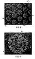
- the specific geometric pattern shown in the photomicrograph of FIGURE 3 e.g., the dot matrix pattern
- the specific geometric pattern shown in the photomicrograph of FIGURE 3 has a density of thermal fuse material regions 12b of about 648 per square inch, a frequency of 25 regions per linear inch, and about 52% open area (i.e., the percentage of the total substrate 12a surface represented by those areas referenced by numeral 12c in FIGURE 3).
- any geometric pattern may be successfully utilized in the practice of this invention.
- the regions 12b of thermal fuse material may themselves be permeable due to the presence of open pores (a representative few of which are identified in FIGURES 4 and 5 by reference numeral 12d). These open pores 12d thereby permit at least some ionic migration to occur through the regions 12b during normal battery operation.
- open pores 12d thereby permit at least some ionic migration to occur through the regions 12b during normal battery operation.
- the thermal fuse material regions 12b are themselves permeable (i.e., due to the presence of pores 12d)
- a lesser impediment to the migration of ions during normal battery operation will ensue as compared to nonpermeable forms of regions 12b.
- the pores 12d may be formed when the carrier liquid is removed and/or when the particulate thermal fuse material coalesces (e.g., upon drying at elevated temperatures near the melting point of the particulate thermal fuse material).
- any suitable porous substrate may advantageously be used in the separators of this invention provided it is (i) sufficiently permeable to migration of positive and negative ions, (ii) compatible with the other battery components, and (iii) provides a suitable surface to which a geometric array of thermal fuse material may be adhered.
- the substrate may be porous film or fabric (e.g., in woven or non-woven form).
- the substrate is an open-celled, microporous polymeric membrane of the type disclosed, for example, in U.S. Patent Nos. 3,558,764 to Isaacson et al issued January 26, 1971; 3,679,538 to Druin et al issued July 25, 1972; and/or 3,843,761 to Biernbaum et al issued on October 22, 1974, the entire content of each of these prior-issued U.S. Patents being expressly incorporated hereinto by reference.
- the preferred microporous film substrates useable in the battery separators of the present invention may be made from a non-porous precursor film, for example, according to the techniques of the U.S. Patents mentioned immediately above.
- microporous membranes will usually be formed from films of olefinic resins, e.g., polypropylene, or polyethylene, but membranes formed from films of other resins may also be employed depending, for example, upon the particular battery components with which the membranes will be used.
- olefinic resins e.g., polypropylene, or polyethylene
- membranes formed from films of other resins may also be employed depending, for example, upon the particular battery components with which the membranes will be used.
- the pores of the preferred microporous film substrates are essentially interconnected through tortuous paths which may extend from one exterior surface or surface region to another, i.e., open-celled. These preferred microporous films will thus exhibit a reduced bulk density as compared with the density of their corresponding precursor film having no open-celled structure.
- the microporous films will preferably have a bulk density of no greater than about 95 percent, and usually between about 50 and 70 percent of the starting non-porous precursor film.
- Gurley Units is the time, in seconds, required for ten cubic centimeters of air to pass through one square inch of membrane in a direction from one of the membrane's exterior surfaces to its other exterior surface under a pressure differential of 12.2 inches of water across the membrane. Since permeability is a measure of the ease of mass transfer across the membrane, lower Gurley Units correspond to lower mass transfer times, and hence correspond to higher permeabilities and a concomitant greater ease of mass transfer across the membrane.
- the pores of the preferred microporous film substrates useable in the separators of the present invention are microscopic, i.e., the details of the pore configuration or arrangement are described only in terms of microscopic dimensions.
- the open cells or pores in the film are smaller than those which can be measured using an ordinary light microscope, because the wavelength of visible light, which is about 5,000 Angstroms, is longer than the longest planar or surface dimension of the open cell or pore.
- the pore size of the microporous films may be defined by using electron microscopy techniques which are capable of resolving details of pore structure below 5,000 Angstroms or by mercury porosimitry techniques.
- the average effective pore size of the microporous films useable as substrates in the practice of this invention is preferably between 50 to 5000 Angstroms, and more typically between 150 to 5000 Angstroms.
- average effective pore size is meant the smallest dimension of a pore which would allow a generally spherical particle of that same dimension to pass therethrough.
- the pores generally have an elongated shape with a width of from 50 to 5000 Angstroms, and a length of from 500 to 10,000 Angstroms.
- the "average effective pore size" of the preferred microporous films will usually be determined by the width dimension of the pores.
- Microporous polymeric films of the type described above are commercially available from Hoechst Celanese Corporation, Separations Products Division, Charlotte, North Carolina under the registered trademark CELGARD®.
- thermal fuse material Any material may be used as the thermal fuse material according to the present invention provided that it melts at or near the "design" elevated internal threshold temperature of the battery in which the separator is to be employed, and exhibits the desired melt flow index so as to spread sufficiently over the normally open areas on the surface of the substrate (thereby providing significantly increased resistance (decreased permeability) to the migration of positive and negative ions through the separator).
- thermal fuse material is meant to refer to any material which melts at or near the predetermined internal elevated threshold temperature of the battery, yet below the melt temperature of the underlying substrate.
- the thermal fuse material preferably has a melting point at least 10°C. less than the melting point of the underlying porous substrate to which it is adhered.
- thermal fuse material in combination with any particular underlying porous substrate is within the skill of those in this art. Suffice it to say here, however, that both the thermal fuse material and the porous substrate on which the material is adhered must be compatible with one another and with the other battery components and must otherwise respond in the desired manner during both normal and abnormal battery operating conditions. However, within these design criteria, a large number of possible thermal fuse material/substrate combinations exist, depending upon the particular electrochemical battery type with which the separator is intended to be used.
- the thermal fuse material will have a melting point of at least about 30° C., and usually between about 50° C. to about 200° C. These melting point temperatures will therefore be at or near the threshold internal elevated temperature of the battery in which thermal protection is desired. That is, for a desired battery threshold temperature (indicative of abnormal battery operating conditions), a thermal fuse material will be selected having a melting point at or near that same threshold temperature. Hence, the thermal fuse material predetermines the threshold temperature of the battery at or above which the electrochemical reaction within the battery is at least significantly minimized to an extent whereby the reaction practically (if not actually) ceases.
- thermal fuse material Another important criterion for any successful thermal fuse material is its ability to "spread" on the surface of the underlying porous substrate when melted so that it effectively covers the normally open areas of the substrate surface.
- the thermal fuse material should exhibit a Melt Flow Index (as quantified, e.g., by ASTM D-1238, condition 190/2.16) of at least about 10 grams per ten minutes, and more preferably, at least about 200 grams per ten minutes or more.
- thermal fuse material may be selected for use in the present invention provided it meets the criteria described above -- that is, has a melting point below the melting point of the substrate on which it is adhered, and exhibits the desired flow characteristics when melted.
- the thermal fuse materials may be those waxes identified in previously mentioned U.S. Patent No. 4,741,979 (the entire content of which is expressly incorporated hereinto by reference), in addition to a number of thermoplastic polymers, such as, for example, polyethylene (Allied Signal, Inc., Grades C-9, C-6 C-5, C-18, or A-617), low-density polyethylene (Plast Labor, SA, CoathyleneTM HA1591, or HX1591), or ethylene-vinyl acetate copolymer (Allied-Signal, Inc., Grades 400, 405, or 430; Plast Labor, SA, CoathyleneTM CB3547).
- the thermoplastic materials will be in the form of finely divided particles (e.g., average particle size of less than about 75 microns), but waxes of such thermoplastic materials may also be used, if desired.
- thermoplastic fuse material be applied to the substrate in the form of a paste which comprises a major amount of the thermal fuse material in particulate form in an inert carrier liquid (e.g., water), and optionally one or more processing and/or property-enhancing aids (e.g., surfactants, thickeners, adhesive agents and the like) in amounts to achieve desired effects for the paste (e.g., less than about 20 weight percent).
- an inert carrier liquid e.g., water
- processing and/or property-enhancing aids e.g., surfactants, thickeners, adhesive agents and the like
- the carrier liquid which may be employed in the thermoplastic paste formulations may be virtually any liquid which is a nonsolvent for the particular thermoplastic material that is used. It is particularly preferred to employ water as the carrier liquid due to its availability, non-toxicity, and cost. Organic liquids may also be employed however, provided that they are nonsolvents for the thermoplastic material. For example, when polyethylene is employed as the thermoplastic material, organic alcohols, such as ethanol, and the like, may satisfactorily be used.
- processing aids and property-enhancing aids may be employed in paste formulations having the thermal fuse material according to this invention.
- processing aids and property-enhancing aids may be employed in paste formulations having the thermal fuse material according to this invention.
- the following preferred processing and/or property-enhancing aids may be employed.
- Preferred surfactants include those characterized by a symmetrically substituted two carbon backbone with a triple bond, two adjacent hydroxyl groups and four symmetrical methyl groups. Included within this definition is acetylenic diol, either alone or in admixture with other organic alcohols, such as, 2-ethylhexanol, ethylene glycol, propylene glycol, 2-butoxyethanol, and isopropyl alcohol. Surfactants of this type are commercially available from Air Products and Chemicals, Inc., under the trademark Surfynol®.
- Another class of surfactants are 1-hydroxyethyl-2-alkylimidazolines. Preferred are those having 7-17 carbon atom alkyl radicals attached to the carbon atom occupying the 2-position in the imidazoline. These surfactants are also commercially available from MONA Industries, Inc. under the tradename MonazolinesTM.
- surfactants include poly(alkaleneoxy) alcohols, with nonylphenoxy poly(ethylenepoxy)ethanol and dodecylphenoxypoly(ethyleneoxy) ethanol being paritucularly preferred. These preferred surfactants are commercially available from GAF Corporation, under the trademark IGEPAL®, with IGEPAL® CO-430 and IGEPAL® RC-630 being particularly preferred.
- Another class of surfactants includes nonioninc block copolymers of propylene oxide and ethylene oxide which are commercially available from BASF Corporation under the trademark Pluronic®. Particularly preferred are block copolymers of propylene oxide and ethylene oxide identified as Pluronic® L-101 and Pluronic® L-62 surfactants.
- thickening agents may be employed so as to ensure that the paste formulations exhibit the desired flow characteristics during their application onto the porous substrate.
- starch and cellulosic-based thickeners e.g., methyl cellulose, carboxymethyl cellulose, and the like
- cellulosic-based thickeners e.g., methyl cellulose, carboxymethyl cellulose, and the like
- Adhesive agents may be employed in the paste formulations to enhance the bonding of the particles of thermoplastic material one to another and to the porous substrate.
- Preferred adhesive agents include emulsions of vinyl acetate copolymers, with emulsions of vinyl acetate-ethylene copolymer and a partially acetylated polyvinyl alcohol being particularly preferred. These preferred adhesive agents are commercially available from Air Products and Chemicals, Inc. under the tradename Airflex®. Of These, Airflex® 400 has been found to be particularly useful as an adhesive agent.
- the carrier liquid is then removed (e.g., by drying at elevated temperatures) so that the particulate thermal fuse material remains as a residue on the surface of the porous substrate, but is retained in the geometric array.
- the elevated temperatures employed during drying and the residence time that the separators of this invention are exposed to such elevated temperatures are dependent upon the particular paste formulation of the thermal fuse material that is used.
- the temperature employed to remove the carrier liquid during the drying step should however be below the melting point temperature of the particular thermoplastic used as the thermal fuse material. Otherwise, the thermal fuse material would melt and spread on the substrate surface during production.
- the elevated temperature at which the thermal fuse material paste is dried should be at least about 2°C (preferably at least about 5°C) below the melting point temperature of the thermoplastic fuse material.
- the residence time during which the thermal fuse material is exposed to the elevated temperature should be sufficiently long so that the carrier liquid is removed from the paste -- i.e., so that the thermoplastic material remains as a dried residue on the surface of the porous substrate.
- the particulate thermoplastic material should not melt and spread on the substrate surface during drying, it is sometimes preferred that the individual thermoplastic particles at least partially melt (i.e., coalesce) so as to fuse one to another and to the substrate's surface.
- paste formulations of the thermal fuse material include an adhesive agent, it is usually unnecessary to coalesce the particulate thermoplastic (i.e., since the adhesive agent serves to bond the particles of thermoplastic material one to another and to the porous substrate's surface). In such situations, the temperatures and residence times may be less as compared to temperatures employed to dry paste formulations in which no adhesive agent is used. In general, therefore, the substrate and thermal fuse material are usually exposed during drying to elevated temperatures for between a few minutes to less than about one hour.
- the thermal fuse material may alternatively be applied onto the surface of the porous substrate in the form of a hot melt.
- the melt is allowed to solidify (e.g., by cooling) on the substrate's surface so as to maintain the established geometric array.
- the thermal fuse material may be applied to one surface, or both surfaces, of the porous substrate in any convenient manner. If applied to one surface only, it is preferred that the surface on which no thermal fuse material is adhered face the cathode in the battery -- i.e., so that the surface on which the thermal fuse material is adhered faces the anode.
- the geometric array of thermal fuse material may, for example, conveniently be applied to the porous substrate via conventional printing techniques, such as screen printing and rotogravure printing techniques.
- screen printing technique involves overlaying an apertured screen which establishes the desired geometric array.
- a paste or melt of the thermal fuse material (e.g., as above described) may then be forced through the screen apertures so as to be deposited onto the substrate surface in a geometric array corresponding to that of the screen apertures.
- the rotogravure printing technique generally involves supplying an unmetered amount of the thermal fuse material in the form of a paste onto the exterior surface of a rotatable patterned gravure cylinder. A doctor blade scrapes excess paste from the gravure cylinder's surface. The porous substrate may then be brought into contact with the cylinder's surface so as to cause the paste thereon to be transferred onto the substrate's surface in same pattern as that on the gravure cylinder's surface.
- the thermal fuse material In use, when the temperature within the battery is at or near the threshold temperature, the thermal fuse material will melt and flow onto the normally open areas of the substrate surface. This melting and flow of thermal fuse material will therefore essentially block the permeability of the normally open areas thereby increasing the overall resistance (decrease the overall permeability) of the separator which, in turn, effectively terminates the electrochemical reaction occurring within the battery.
- the separators of this invention should provide an increase in terms of Gurley Units during a "shutdown" condition (i.e., during a condition whereby the integral thermal fuse is activated) which is at least about 100% greater than the Gurley Units of the separators during normal operating conditions.
- a threshold temperature of about 120°C. the separators should exhibit about a 500% increase in Gurley Units.
- thermoplastic paste formulations in the following Examples are expressed in terms of the components' percent by weight based on the total weight of the formulation.
- the separator samples were subjected to elevated temperature conditions simulating the abnormal internal temperature conditions which would exist within a battery cell, and which would necessitate activation of the integral thermal fuse according to this invention.
- 3 inch by 6 inch samples of the separators were placed between the plates of a commercial hot plate (Black & Decker Grill Wafflebaker, Cat.# Z1G48TD) controlled so that the samples were exposed to increasing temperature from ambient to a set temperature of 70°C. or 150°C. at a rate of 5.4°C. per minute.
- the side of the separator on which the thermal fuse material was adhered was placed on top of a Teflon® coated fabric (in which a thermocouple had been threaded substantially at its midline) so that the thermal fuse material was face up against the lid of the hot plate.
- the bottommost plate of the hot plate was covered with a similar Teflon® coated fabric over which a 0.25 inch thick aluminum plate was placed.
- a layer of poster board having a 0.5 inch slit at approximately its midline was placed between the aluminum plate and the Teflon® coated fabric bearing the separator samples to be tested. The slit in the poster board was provided so that the thermocouple more accurately measured the temperature of the hot plate, and hence provided more accurate control over the temperature to which the separator samples were exposed.
- Adhesion values were determined by applying masking tape to the separator on the side to which the thermal fuse material had been applied and then visually determining the amount of thermal fuse material adhered to the tape when it was removed. Values between 4 (designating no thermal fuse material stuck to the tape) and 0 (designating total removal of the thermal fuse material by the tape) were ascribed to the samples according to this test.
- the paste was applied to a surface of a microporous polypropylene film (Celgard® 2500, Hoechst Celanese Corporation) by screen printing using an 83 mesh screen.
- the thermal fuse material was then dried by placing the screen-printed substrate (taped to a stainless steel plate) in a laboratory oven (Fisher Model 116G) at a temperature of 90-95°C for about 50 minutes.
- the separator had an overall thickness of 7.0 mils after drying.
- the separator exhibited an adhesion value of 3, and a permeability of 13.1 Initial Gurley Units. The separator was then subjected to the battery failure simulation test and exhibited a permeability of greater than 8400 Shutdown Gurley Units at 125°C thereby indicating satisfactory thermal fuse properties.
- Example I was repeated except that the low density polyethylene was present in an amount of 62% and 0.4% surfactant (Igepal® RC630, GAF Corporation) was employed in the thermal fuse material paste.
- the paste was then screen-printed onto a surface of a microporous polypropylene substrate (Celgard® 2500) using a 60 mesh screen and was dried in the manner described in Example I.
- the separator had an overall thickness of 8.0 mils after drying.
- the separator exhibited an adhesion value of 3, and a permeability of 10.4 Initial Gurley Units.
- the separator was then subjected to the battery failure simulation test and exhibited a permeability of greater than 12,000 Shutdown Gurley Units at 125°C thereby indicating satisfactory thermal shutdown properties.
- the paste was applied to a surface of a microporous polypropylene film (Celgard® 2500) by screen printing using an 60 mesh screen and was dried in the manner described in Example 1.
- the separator had an overall thickness of 18.0 mils after drying.
- the separator exhibited an adhesion value of 4, and a permeability of 18.0 Initial Gurley Units.
- the separator was then subjected to the battery failure simulation test and exhibited a permeability of 3,392 Shutdown Gurley Units at 125°C thereby indicating satisfactory thermal fuse properties.
- Example III was repeated except that the paste was screen printed onto the surface of the substrate using an 83 mesh screen.
- the separator had an overall thickness of 5.0 mils after drying and exhibited an adhesion value of 3, and a permeability of 12.3 Initial Gurley Units. The separator was then subjected to the battery failure simulation test and exhibited a permeability of 354 Shutdown Gurley Units at 125°C thereby indicating satisfactory thermal fuse properties.
- a thermal fuse material paste was prepared mixing 45% particulate polyethylene wax (Shamrock S-394, Shamrock Technologies, Inc.), 9.5% of an adhesive agent (Airflex® 400, Air Products and Chemicals, Inc.), 0.6% total surfactant (i.e., 0.2% Igepal® RC630, 0.2% Igepal® C0430, GAF Corporation, and 0.2% Surfynol®, Air Products and Chemicals, Inc.), and the balance water.
- a piece of rubber 6 inches x 12 inches x 1/4 inch was secured to a laboratory bench top, and a similarly sized piece of microporous polypropylene film (Celgard® 2500) was secured over the rubber.
- the paste was applied to the surface of the film by feeding a manual gravure applicator roll with small quantities of the paste while moving the roll across the film's surface.
- the applicator roll contained 18 quadrangular cells per linear inch, each cell being approximately 1mm x 1mm, and spaced apart by 0.1mm.
- the gravure-printed film was then dried in a laboratory oven (Fisher Model 116G) at 80°C for 15 minutes.
- the resulting battery separator had a thickness of 6.5 mils after drying, and exhibited an adhesion value of 3 and a permeability of 8.1 Initial Gurley Units.
- the separator was then subjected to the battery failure simulation test and exhibited permeabilities of 24 Gurley Units at 110°C, 1,000 Gurley Units at 115°C, and greater than 30,000 Gurley Units at 125°C thereby corresponding to an increase over the Initial Gurley Units of 196%, 12,246% and 370,000%, respectively.
- the paste was applied to a surface of a microporous polypropylene film (Celgard® 2500) by screen printing using a 60 mesh screen.
- the sample was then dried in a laboratory oven for 50 minutes at 90-95°C.
- the resulting separator had an overall thickness of 6.3 mils after drying.
- the separator exhibited an adhesion value of 3, and a permeability of 9.7 Initial Gurley Units.
- the separator was then subjected to the battery failure simulation test and exhibited a permeability of greater than 12,000 Gurley Units after heating to 125°C. thereby indicating satisfactory thermal fuse properties.
- Example VI was repeated using a paste formulation comprised of 48% particulate low density polyethylene (Plast-Labor, S.A., CoathyleneTM HA1591), 0.4% surfactant (Pluronic® L-62), and the balance water.
- the separator exhibited an adhesion value of 3, and a permeability of 9.0 Initial Gurley Units. After being subjected to the battery failure simulation test to a temperature of 125°C, the permeability of the separator was greater than 12,000 Gurley Units thereby indicating satisfactory thermal fuse properties.
- the paste was applied to a surface of a microporous polyethylene film (Celgard® K-864) by screen printing using a 60 mesh screen.
- the sample was then dried in a laboratory oven for 50 minutes at 90-95°C.
- the resulting separator had an overall thickness of 7.2 mils after drying.
- the separator exhibited an adhesion value of 3, and a permeability of 5.0 Initial Gurley Units.
- the separator was then subjected to the battery failure simulation test and exhibited a permeability of greater than 23.2 Gurley Units after heating to 100°C., and 488.8 Gurley Units after heating to 110°C, thereby indicating satisfactory thermal fuse properties.
- the separators of the present invention demonstrate the effectiveness of the separators of the present invention to significantly increase in permeability in response to elevated temperatures, while exhibiting satisfactory permeabilities under normal temperatures.
- the separators of this invention are well suited for use in batteries as a means to provide a thermal fuse since such decreased permeabilities at elevated temperatures would significantly reduce the ionic migration between the anode and cathode in the battery, thereby providing a "shutdown" capability to the battery in the event of battery malfunction and/or improper battery use.
Landscapes
- Chemical & Material Sciences (AREA)
- Chemical Kinetics & Catalysis (AREA)
- Electrochemistry (AREA)
- General Chemical & Material Sciences (AREA)
- Engineering & Computer Science (AREA)
- Manufacturing & Machinery (AREA)
- Cell Separators (AREA)
Applications Claiming Priority (2)
| Application Number | Priority Date | Filing Date | Title |
|---|---|---|---|
| US07/333,662 US4973532A (en) | 1989-04-05 | 1989-04-05 | Battery separator with integral thermal fuse |
| US333662 | 1994-11-03 |
Publications (3)
| Publication Number | Publication Date |
|---|---|
| EP0391694A2 true EP0391694A2 (fr) | 1990-10-10 |
| EP0391694A3 EP0391694A3 (fr) | 1991-03-27 |
| EP0391694B1 EP0391694B1 (fr) | 1994-11-17 |
Family
ID=23303739
Family Applications (1)
| Application Number | Title | Priority Date | Filing Date |
|---|---|---|---|
| EP90303626A Expired - Lifetime EP0391694B1 (fr) | 1989-04-05 | 1990-04-04 | Séparateur de batterie à fusible thermique intégré |
Country Status (8)
| Country | Link |
|---|---|
| US (1) | US4973532A (fr) |
| EP (1) | EP0391694B1 (fr) |
| JP (1) | JPH0770309B2 (fr) |
| KR (1) | KR950001254B1 (fr) |
| CA (1) | CA2013202C (fr) |
| DE (1) | DE69014148T2 (fr) |
| ES (1) | ES2064617T3 (fr) |
| IL (1) | IL93987A (fr) |
Cited By (44)
| Publication number | Priority date | Publication date | Assignee | Title |
|---|---|---|---|---|
| EP0550262A1 (fr) * | 1991-12-27 | 1993-07-07 | W.R. Grace & Co.-Conn. | Membrane poreuse à structure monocouche, séparateur de batterie fabriqué de cette membrane, fabrications de ceux-ci et batterie munie de ce séparateur de batterie |
| WO2000044061A1 (fr) * | 1999-01-23 | 2000-07-27 | Fortu Bat Batterien Gmbh | Cellule electrochimique non aqueuse |
| KR100292978B1 (ko) * | 1991-12-27 | 2001-06-15 | 로버트 에이치. 해머3세 | 단층구조의 다공성 막 및 이를 포함하는 전지 격리판과 전지 |
| WO2005048384A3 (fr) * | 2003-11-06 | 2005-07-21 | Tiax Llc | Separateur pour dispositifs electrochimiques et procedes correspondants |
| US8963550B2 (en) | 2004-08-20 | 2015-02-24 | Midtronics, Inc. | System for automatically gathering battery information |
| US9018958B2 (en) | 2003-09-05 | 2015-04-28 | Midtronics, Inc. | Method and apparatus for measuring a parameter of a vehicle electrical system |
| US9201120B2 (en) | 2010-08-12 | 2015-12-01 | Midtronics, Inc. | Electronic battery tester for testing storage battery |
| US9229062B2 (en) | 2010-05-27 | 2016-01-05 | Midtronics, Inc. | Electronic storage battery diagnostic system |
| US9244100B2 (en) | 2013-03-15 | 2016-01-26 | Midtronics, Inc. | Current clamp with jaw closure detection |
| US9255955B2 (en) | 2003-09-05 | 2016-02-09 | Midtronics, Inc. | Method and apparatus for measuring a parameter of a vehicle electrical system |
| US9274157B2 (en) | 2007-07-17 | 2016-03-01 | Midtronics, Inc. | Battery tester for electric vehicle |
| US9312575B2 (en) | 2013-05-16 | 2016-04-12 | Midtronics, Inc. | Battery testing system and method |
| US9335362B2 (en) | 2007-07-17 | 2016-05-10 | Midtronics, Inc. | Battery tester for electric vehicle |
| US9419311B2 (en) | 2010-06-18 | 2016-08-16 | Midtronics, Inc. | Battery maintenance device with thermal buffer |
| US9425487B2 (en) | 2010-03-03 | 2016-08-23 | Midtronics, Inc. | Monitor for front terminal batteries |
| US9496720B2 (en) | 2004-08-20 | 2016-11-15 | Midtronics, Inc. | System for automatically gathering battery information |
| US9588185B2 (en) | 2010-02-25 | 2017-03-07 | Keith S. Champlin | Method and apparatus for detecting cell deterioration in an electrochemical cell or battery |
| US9851411B2 (en) | 2012-06-28 | 2017-12-26 | Keith S. Champlin | Suppressing HF cable oscillations during dynamic measurements of cells and batteries |
| US9923289B2 (en) | 2014-01-16 | 2018-03-20 | Midtronics, Inc. | Battery clamp with endoskeleton design |
| US9966676B2 (en) | 2015-09-28 | 2018-05-08 | Midtronics, Inc. | Kelvin connector adapter for storage battery |
| US10046649B2 (en) | 2012-06-28 | 2018-08-14 | Midtronics, Inc. | Hybrid and electric vehicle battery pack maintenance device |
| US10222397B2 (en) | 2014-09-26 | 2019-03-05 | Midtronics, Inc. | Cable connector for electronic battery tester |
| US10317468B2 (en) | 2015-01-26 | 2019-06-11 | Midtronics, Inc. | Alternator tester |
| US10429449B2 (en) | 2011-11-10 | 2019-10-01 | Midtronics, Inc. | Battery pack tester |
| US10473555B2 (en) | 2014-07-14 | 2019-11-12 | Midtronics, Inc. | Automotive maintenance system |
| US10608353B2 (en) | 2016-06-28 | 2020-03-31 | Midtronics, Inc. | Battery clamp |
| US10843574B2 (en) | 2013-12-12 | 2020-11-24 | Midtronics, Inc. | Calibration and programming of in-vehicle battery sensors |
| US11054480B2 (en) | 2016-10-25 | 2021-07-06 | Midtronics, Inc. | Electrical load for electronic battery tester and electronic battery tester including such electrical load |
| US11325479B2 (en) | 2012-06-28 | 2022-05-10 | Midtronics, Inc. | Hybrid and electric vehicle battery maintenance device |
| US11474153B2 (en) | 2019-11-12 | 2022-10-18 | Midtronics, Inc. | Battery pack maintenance system |
| US11486930B2 (en) | 2020-01-23 | 2022-11-01 | Midtronics, Inc. | Electronic battery tester with battery clamp storage holsters |
| US11513160B2 (en) | 2018-11-29 | 2022-11-29 | Midtronics, Inc. | Vehicle battery maintenance device |
| US11545839B2 (en) | 2019-11-05 | 2023-01-03 | Midtronics, Inc. | System for charging a series of connected batteries |
| US11566972B2 (en) | 2019-07-31 | 2023-01-31 | Midtronics, Inc. | Tire tread gauge using visual indicator |
| US11650259B2 (en) | 2010-06-03 | 2023-05-16 | Midtronics, Inc. | Battery pack maintenance for electric vehicle |
| US11668779B2 (en) | 2019-11-11 | 2023-06-06 | Midtronics, Inc. | Hybrid and electric vehicle battery pack maintenance device |
| US11740294B2 (en) | 2010-06-03 | 2023-08-29 | Midtronics, Inc. | High use battery pack maintenance |
| US11973202B2 (en) | 2019-12-31 | 2024-04-30 | Midtronics, Inc. | Intelligent module interface for battery maintenance device |
| US12237482B2 (en) | 2019-12-31 | 2025-02-25 | Midtronics, Inc. | Intelligent module interface for battery maintenance device |
| US12320857B2 (en) | 2016-10-25 | 2025-06-03 | Midtronics, Inc. | Electrical load for electronic battery tester and electronic battery tester including such electrical load |
| US12330513B2 (en) | 2022-02-14 | 2025-06-17 | Midtronics, Inc. | Battery maintenance device with high voltage connector |
| US12392833B2 (en) | 2022-05-09 | 2025-08-19 | Midtronics, Inc. | Electronic battery tester |
| US12517178B2 (en) | 2021-05-27 | 2026-01-06 | Midtronics, Inc. | Battery monitoring system |
| US12555965B2 (en) | 2021-08-24 | 2026-02-17 | Midtronics, Inc. | Power adapter for automotive vehicle maintenance device |
Families Citing this family (28)
| Publication number | Priority date | Publication date | Assignee | Title |
|---|---|---|---|---|
| US5091272A (en) * | 1990-05-29 | 1992-02-25 | Duracell Inc. | Separator for electrochemical cells |
| USH985H (en) | 1990-09-25 | 1991-11-05 | The United States Of America As Represented By The Secretary Of The Army | Cell compartment for battery matrix |
| EP0503969A1 (fr) * | 1991-03-13 | 1992-09-16 | Wilson Greatbatch Ltd. | Pile à metal alcalin avec un séparateur de protection thermique |
| JPH07106310B2 (ja) * | 1991-12-13 | 1995-11-15 | 株式会社井上製作所 | 媒体分散機 |
| DE69231694T2 (de) * | 1991-12-20 | 2001-08-02 | Celgard Inc., Burlington | Separator für mehrschichtbatterie und herstellungsverfahren |
| US5281491A (en) * | 1991-12-20 | 1994-01-25 | W. R. Grace & Co. | Battery separator |
| US5591542A (en) * | 1993-02-09 | 1997-01-07 | Sumitomo Electric Industries, Ltd. | Battery diaphragm and battery with such a diaphragm |
| JP3352801B2 (ja) * | 1994-01-31 | 2002-12-03 | 日東電工株式会社 | 多孔質フィルム、その製造法およびその用途 |
| US5534365A (en) * | 1994-06-07 | 1996-07-09 | Gee; Michael A. | Battery with fusible solid electrolyte |
| US5527569A (en) * | 1994-08-22 | 1996-06-18 | W. L. Gore & Associates, Inc. | Conductive filter laminate |
| US5891589A (en) * | 1997-05-19 | 1999-04-06 | Aer Energy Resources, Inc. | Method and apparatus for joining metal-air cells |
| US6150051A (en) * | 1998-02-27 | 2000-11-21 | Telcordia Technologies, Inc. | Thermal switch for use in plastic batteries |
| EP1095420A1 (fr) | 1998-06-08 | 2001-05-02 | Moltech Corporation | Monomeres multi-fonctionnels reactifs aux fins de la protection de cellules electrochimiques non aqueuses |
| US6562511B2 (en) * | 1999-12-09 | 2003-05-13 | Ntk Powerdex, Inc. | Battery separator for Li-Ion and/or Li-Ion polymer battery |
| US6531238B1 (en) | 2000-09-26 | 2003-03-11 | Reliant Energy Power Systems, Inc. | Mass transport for ternary reaction optimization in a proton exchange membrane fuel cell assembly and stack assembly |
| JP4748853B2 (ja) * | 2000-12-28 | 2011-08-17 | 株式会社ワコール | 乳房カップを有する衣料 |
| US6881515B2 (en) * | 2001-05-08 | 2005-04-19 | Celgard Inc. | Separator for polymer battery |
| EP1296389A1 (fr) * | 2001-09-19 | 2003-03-26 | Wilson Greatbatch Technologies, Inc. | Oxide d'argent et de vanadium d'une fine granulométrie pour performance améliorée d'une cellule électrochimique |
| RU2293401C2 (ru) * | 2004-04-16 | 2007-02-10 | Сергей Александрович Галкин | Химический источник тока системы диоксид марганца - литий |
| US8945753B2 (en) * | 2005-01-26 | 2015-02-03 | Medtronic, Inc. | Implantable battery having thermal shutdown separator |
| US20070178385A1 (en) * | 2006-01-31 | 2007-08-02 | Kaimin Chen | Electrochemical cells having an electrolyte with swelling reducing additives |
| US8377583B2 (en) * | 2008-01-30 | 2013-02-19 | Lg Chem, Ltd. | Separator for providing a uniting force to electrode and electrochemical cell containing the same |
| DE102009027072A1 (de) | 2009-06-22 | 2010-12-23 | Zf Friedrichshafen Ag | Schaltungsanordnung |
| KR20150057480A (ko) * | 2013-11-19 | 2015-05-28 | 삼성에스디아이 주식회사 | 세퍼레이터, 이를 포함하는 리튬 전지, 상기 세퍼레이터의 제조방법, 및 상기 리튬 전지의 제조방법 |
| KR102246767B1 (ko) | 2014-08-13 | 2021-04-30 | 삼성에스디아이 주식회사 | 리튬이차전지용 세퍼레이터, 이를 채용한 리튬이차전지 및 그 제조방법 |
| CN111180649B (zh) * | 2019-12-30 | 2021-06-11 | 合肥国轩高科动力能源有限公司 | 一体式高温分解接插件及含有该接插件的锂离子电池 |
| JP7431943B2 (ja) * | 2020-03-27 | 2024-02-15 | 三井化学株式会社 | リチウムイオン電池用自己消火性フィルム及びその製造方法、並びに、リチウムイオン電池 |
| EP4681278A1 (fr) * | 2023-03-14 | 2026-01-21 | Polyjoule, Inc. | Électrodes monolithiques à chargement élevé |
Family Cites Families (25)
| Publication number | Priority date | Publication date | Assignee | Title |
|---|---|---|---|---|
| US3228790A (en) * | 1961-05-26 | 1966-01-11 | Johnson & Johnson | Nonwoven fabric containing polyolefin fibers bonded together with a mixture of polyolefin and acrylic resins |
| US3380851A (en) * | 1965-03-31 | 1968-04-30 | Air Reduction | Nonwoven fabric with vinyl acetateethylene-n-methylol acrylamide interpolymer as binder |
| US3558764A (en) * | 1966-09-06 | 1971-01-26 | Celanese Corp | Process for preparing microporous film |
| JPS456657Y1 (fr) * | 1966-12-21 | 1970-04-02 | ||
| US3679538A (en) * | 1970-10-28 | 1972-07-25 | Celanese Corp | Novel open-celled microporous film |
| US3843761A (en) * | 1973-05-30 | 1974-10-22 | Celanese Corp | Process for preparing a thermoplastic microporous film involving a cold stretching step and multiple hot stretching steps |
| US4075400A (en) * | 1977-02-04 | 1978-02-21 | Fritts David H | Over temperature battery deactivation system |
| DE2933217A1 (de) * | 1978-08-30 | 1980-03-13 | Grace W R & Co | Verfahren zur herstellung von batteriescheidern |
| US4407910A (en) * | 1979-04-23 | 1983-10-04 | Catanzarite Vincent Owen | Anode neutralization |
| US4363856A (en) * | 1980-06-30 | 1982-12-14 | Texon Inc. | Battery separator material |
| US4351888A (en) * | 1981-07-30 | 1982-09-28 | Gte Laboratories Incorporated | Electrochemical cell |
| ZA825809B (en) * | 1981-08-12 | 1983-08-31 | Smith & Nephew Ass | Adhesive dressing and components |
| JPS6052A (ja) * | 1983-06-15 | 1985-01-05 | Fuji Elelctrochem Co Ltd | 非水電解液電池 |
| JPS6023954A (ja) * | 1983-07-18 | 1985-02-06 | Sanyo Electric Co Ltd | 非水電解液電池 |
| JPS60136161A (ja) * | 1983-12-26 | 1985-07-19 | Japan Vilene Co Ltd | リチウム電池用セパレ−タ材 |
| JPS61232560A (ja) * | 1985-04-08 | 1986-10-16 | Fuji Elelctrochem Co Ltd | リチウム電池 |
| US4650730A (en) * | 1985-05-16 | 1987-03-17 | W. R. Grace & Co. | Battery separator |
| US4719159A (en) * | 1986-05-19 | 1988-01-12 | Eastman Kodak Company | Sealed lithium battery |
| US4741979A (en) * | 1986-05-19 | 1988-05-03 | Eastman Kodak Company | Battery separator assembly |
| JPH0616418B2 (ja) * | 1986-09-30 | 1994-03-02 | 富士電気化学株式会社 | 非水電解液電池 |
| JPH0610984B2 (ja) * | 1986-09-30 | 1994-02-09 | 富士電気化学株式会社 | 非水電解液電池 |
| US4734324A (en) * | 1987-03-27 | 1988-03-29 | Hercules Incorporated | Heat sealable microporous polypropylene films |
| JPS63279562A (ja) * | 1987-05-11 | 1988-11-16 | Sanyo Electric Co Ltd | 電池 |
| JPH01258358A (ja) * | 1988-04-06 | 1989-10-16 | Japan Vilene Co Ltd | リチウム電池用セパレータ |
| EP0352617A1 (fr) * | 1988-07-25 | 1990-01-31 | Eastman Kodak Company | Séparatus fusibles pour batteries au lithium |
-
1989
- 1989-04-05 US US07/333,662 patent/US4973532A/en not_active Expired - Lifetime
-
1990
- 1990-03-28 CA CA002013202A patent/CA2013202C/fr not_active Expired - Fee Related
- 1990-04-02 IL IL9398790A patent/IL93987A/en not_active IP Right Cessation
- 1990-04-04 DE DE69014148T patent/DE69014148T2/de not_active Expired - Fee Related
- 1990-04-04 EP EP90303626A patent/EP0391694B1/fr not_active Expired - Lifetime
- 1990-04-04 ES ES90303626T patent/ES2064617T3/es not_active Expired - Lifetime
- 1990-04-04 KR KR1019900004657A patent/KR950001254B1/ko not_active Expired - Fee Related
- 1990-04-05 JP JP2091326A patent/JPH0770309B2/ja not_active Expired - Fee Related
Cited By (47)
| Publication number | Priority date | Publication date | Assignee | Title |
|---|---|---|---|---|
| KR100292978B1 (ko) * | 1991-12-27 | 2001-06-15 | 로버트 에이치. 해머3세 | 단층구조의 다공성 막 및 이를 포함하는 전지 격리판과 전지 |
| EP0550262A1 (fr) * | 1991-12-27 | 1993-07-07 | W.R. Grace & Co.-Conn. | Membrane poreuse à structure monocouche, séparateur de batterie fabriqué de cette membrane, fabrications de ceux-ci et batterie munie de ce séparateur de batterie |
| WO2000044061A1 (fr) * | 1999-01-23 | 2000-07-27 | Fortu Bat Batterien Gmbh | Cellule electrochimique non aqueuse |
| US9018958B2 (en) | 2003-09-05 | 2015-04-28 | Midtronics, Inc. | Method and apparatus for measuring a parameter of a vehicle electrical system |
| US9255955B2 (en) | 2003-09-05 | 2016-02-09 | Midtronics, Inc. | Method and apparatus for measuring a parameter of a vehicle electrical system |
| WO2005048384A3 (fr) * | 2003-11-06 | 2005-07-21 | Tiax Llc | Separateur pour dispositifs electrochimiques et procedes correspondants |
| US9496720B2 (en) | 2004-08-20 | 2016-11-15 | Midtronics, Inc. | System for automatically gathering battery information |
| US8963550B2 (en) | 2004-08-20 | 2015-02-24 | Midtronics, Inc. | System for automatically gathering battery information |
| US9274157B2 (en) | 2007-07-17 | 2016-03-01 | Midtronics, Inc. | Battery tester for electric vehicle |
| US9335362B2 (en) | 2007-07-17 | 2016-05-10 | Midtronics, Inc. | Battery tester for electric vehicle |
| US9588185B2 (en) | 2010-02-25 | 2017-03-07 | Keith S. Champlin | Method and apparatus for detecting cell deterioration in an electrochemical cell or battery |
| US9425487B2 (en) | 2010-03-03 | 2016-08-23 | Midtronics, Inc. | Monitor for front terminal batteries |
| US9229062B2 (en) | 2010-05-27 | 2016-01-05 | Midtronics, Inc. | Electronic storage battery diagnostic system |
| US12196813B2 (en) | 2010-06-03 | 2025-01-14 | Midtronics, Inc. | High use battery pack maintenance |
| US11740294B2 (en) | 2010-06-03 | 2023-08-29 | Midtronics, Inc. | High use battery pack maintenance |
| US11650259B2 (en) | 2010-06-03 | 2023-05-16 | Midtronics, Inc. | Battery pack maintenance for electric vehicle |
| US9419311B2 (en) | 2010-06-18 | 2016-08-16 | Midtronics, Inc. | Battery maintenance device with thermal buffer |
| US9201120B2 (en) | 2010-08-12 | 2015-12-01 | Midtronics, Inc. | Electronic battery tester for testing storage battery |
| US10429449B2 (en) | 2011-11-10 | 2019-10-01 | Midtronics, Inc. | Battery pack tester |
| US9851411B2 (en) | 2012-06-28 | 2017-12-26 | Keith S. Champlin | Suppressing HF cable oscillations during dynamic measurements of cells and batteries |
| US11325479B2 (en) | 2012-06-28 | 2022-05-10 | Midtronics, Inc. | Hybrid and electric vehicle battery maintenance device |
| US11926224B2 (en) | 2012-06-28 | 2024-03-12 | Midtronics, Inc. | Hybrid and electric vehicle battery pack maintenance device |
| US10046649B2 (en) | 2012-06-28 | 2018-08-14 | Midtronics, Inc. | Hybrid and electric vehicle battery pack maintenance device |
| US11548404B2 (en) | 2012-06-28 | 2023-01-10 | Midtronics, Inc. | Hybrid and electric vehicle battery pack maintenance device |
| US9244100B2 (en) | 2013-03-15 | 2016-01-26 | Midtronics, Inc. | Current clamp with jaw closure detection |
| US9312575B2 (en) | 2013-05-16 | 2016-04-12 | Midtronics, Inc. | Battery testing system and method |
| US10843574B2 (en) | 2013-12-12 | 2020-11-24 | Midtronics, Inc. | Calibration and programming of in-vehicle battery sensors |
| US9923289B2 (en) | 2014-01-16 | 2018-03-20 | Midtronics, Inc. | Battery clamp with endoskeleton design |
| US10473555B2 (en) | 2014-07-14 | 2019-11-12 | Midtronics, Inc. | Automotive maintenance system |
| US10222397B2 (en) | 2014-09-26 | 2019-03-05 | Midtronics, Inc. | Cable connector for electronic battery tester |
| US10317468B2 (en) | 2015-01-26 | 2019-06-11 | Midtronics, Inc. | Alternator tester |
| US9966676B2 (en) | 2015-09-28 | 2018-05-08 | Midtronics, Inc. | Kelvin connector adapter for storage battery |
| US10608353B2 (en) | 2016-06-28 | 2020-03-31 | Midtronics, Inc. | Battery clamp |
| US11054480B2 (en) | 2016-10-25 | 2021-07-06 | Midtronics, Inc. | Electrical load for electronic battery tester and electronic battery tester including such electrical load |
| US12320857B2 (en) | 2016-10-25 | 2025-06-03 | Midtronics, Inc. | Electrical load for electronic battery tester and electronic battery tester including such electrical load |
| US11513160B2 (en) | 2018-11-29 | 2022-11-29 | Midtronics, Inc. | Vehicle battery maintenance device |
| US11566972B2 (en) | 2019-07-31 | 2023-01-31 | Midtronics, Inc. | Tire tread gauge using visual indicator |
| US11545839B2 (en) | 2019-11-05 | 2023-01-03 | Midtronics, Inc. | System for charging a series of connected batteries |
| US11668779B2 (en) | 2019-11-11 | 2023-06-06 | Midtronics, Inc. | Hybrid and electric vehicle battery pack maintenance device |
| US11474153B2 (en) | 2019-11-12 | 2022-10-18 | Midtronics, Inc. | Battery pack maintenance system |
| US11973202B2 (en) | 2019-12-31 | 2024-04-30 | Midtronics, Inc. | Intelligent module interface for battery maintenance device |
| US12237482B2 (en) | 2019-12-31 | 2025-02-25 | Midtronics, Inc. | Intelligent module interface for battery maintenance device |
| US11486930B2 (en) | 2020-01-23 | 2022-11-01 | Midtronics, Inc. | Electronic battery tester with battery clamp storage holsters |
| US12517178B2 (en) | 2021-05-27 | 2026-01-06 | Midtronics, Inc. | Battery monitoring system |
| US12555965B2 (en) | 2021-08-24 | 2026-02-17 | Midtronics, Inc. | Power adapter for automotive vehicle maintenance device |
| US12330513B2 (en) | 2022-02-14 | 2025-06-17 | Midtronics, Inc. | Battery maintenance device with high voltage connector |
| US12392833B2 (en) | 2022-05-09 | 2025-08-19 | Midtronics, Inc. | Electronic battery tester |
Also Published As
| Publication number | Publication date |
|---|---|
| IL93987A0 (en) | 1991-01-31 |
| CA2013202C (fr) | 1994-12-13 |
| JPH0770309B2 (ja) | 1995-07-31 |
| EP0391694A3 (fr) | 1991-03-27 |
| DE69014148D1 (de) | 1994-12-22 |
| US4973532A (en) | 1990-11-27 |
| ES2064617T3 (es) | 1995-02-01 |
| CA2013202A1 (fr) | 1990-10-05 |
| JPH0362449A (ja) | 1991-03-18 |
| EP0391694B1 (fr) | 1994-11-17 |
| IL93987A (en) | 1994-01-25 |
| KR900017224A (ko) | 1990-11-15 |
| KR950001254B1 (ko) | 1995-02-15 |
| DE69014148T2 (de) | 1995-03-23 |
Similar Documents
| Publication | Publication Date | Title |
|---|---|---|
| EP0391694B1 (fr) | Séparateur de batterie à fusible thermique intégré | |
| US5091272A (en) | Separator for electrochemical cells | |
| EP1530809B1 (fr) | Separateur electrique a mecanisme d'arret, son procede de production et son utilisation dans des batteries au lithium | |
| EP1673823B1 (fr) | Separateur electrique comportant un mecanisme de coupure, procede de fabrication et utilisation dans des piles au lithium | |
| KR101056590B1 (ko) | X-ray에 의해 감지될 수 있는 배터리 세퍼레이터와 배터리 내에서 세퍼레이터의 위치를 감지하는 방법 | |
| KR101446949B1 (ko) | 미다공막 및 그 제조 방법 | |
| US9799869B2 (en) | Microporous polyolefin composite film having excellent heat resistance and thermal stability and method for manufacturing the same | |
| JP5445885B2 (ja) | 電気化学素子用セパレータ及びその製造方法 | |
| US20070243460A1 (en) | Safety shutdown separators | |
| EP3438177A1 (fr) | Membrane microporeuse en polyoléfine, procédé de production pour membrane microporeuse en polyoléfine, séparateur de batterie et batterie | |
| KR101387388B1 (ko) | 미다공막 및 그 제조 방법 | |
| BRPI0617556A2 (pt) | bateria e bateria de lÍtio | |
| US4315062A (en) | Method for the manufacture of a polystyrene separator and cell | |
| JPH06236752A (ja) | 鉛蓄電池用セパレータ並びにその製造法 | |
| JPH08236093A (ja) | バッテリーセパレーター | |
| US4965147A (en) | Separator for an electrochemical cell of the metal-air type and having an alkaline electrolyte | |
| JPH11207888A (ja) | 複合多孔質体 | |
| JP2009501425A (ja) | バッテリーの分離材 | |
| EP4645567A1 (fr) | Séparateur pour dispositif de stockage d'énergie | |
| EP0352617A1 (fr) | Séparatus fusibles pour batteries au lithium | |
| JP2000044722A (ja) | 熱閉塞性多孔質体 | |
| US20180040866A1 (en) | Laminated porous film, non-aqueous electrolyte secondary battery separator, and non-aqueous electrolyte secondary battery | |
| JP2642206B2 (ja) | 防爆型二次電池 | |
| US20120164502A1 (en) | Galvanic element and separator having improved safety properties | |
| EP4553986A1 (fr) | Séparateur pour dispositif de stockage d'énergie |
Legal Events
| Date | Code | Title | Description |
|---|---|---|---|
| PUAI | Public reference made under article 153(3) epc to a published international application that has entered the european phase |
Free format text: ORIGINAL CODE: 0009012 |
|
| AK | Designated contracting states |
Kind code of ref document: A2 Designated state(s): BE CH DE ES FR GB IT LI NL |
|
| RIN1 | Information on inventor provided before grant (corrected) |
Inventor name: FLEMING, ROBERT J. Inventor name: LANGFORD, ELLEN A. Inventor name: MULLINS, STEVEN M. Inventor name: TASKIER, HENRY T. |
|
| PUAL | Search report despatched |
Free format text: ORIGINAL CODE: 0009013 |
|
| AK | Designated contracting states |
Kind code of ref document: A3 Designated state(s): BE CH DE ES FR GB IT LI NL |
|
| 17P | Request for examination filed |
Effective date: 19910903 |
|
| 17Q | First examination report despatched |
Effective date: 19930108 |
|
| GRAA | (expected) grant |
Free format text: ORIGINAL CODE: 0009210 |
|
| AK | Designated contracting states |
Kind code of ref document: B1 Designated state(s): BE CH DE ES FR GB IT LI NL |
|
| REF | Corresponds to: |
Ref document number: 69014148 Country of ref document: DE Date of ref document: 19941222 |
|
| REG | Reference to a national code |
Ref country code: ES Ref legal event code: FG2A Ref document number: 2064617 Country of ref document: ES Kind code of ref document: T3 |
|
| ITF | It: translation for a ep patent filed | ||
| ET | Fr: translation filed | ||
| PLBE | No opposition filed within time limit |
Free format text: ORIGINAL CODE: 0009261 |
|
| STAA | Information on the status of an ep patent application or granted ep patent |
Free format text: STATUS: NO OPPOSITION FILED WITHIN TIME LIMIT |
|
| 26N | No opposition filed | ||
| REG | Reference to a national code |
Ref country code: CH Ref legal event code: PUE Owner name: HOECHST CELANESE CORPORATION TRANSFER- CELGARD LLC |
|
| NLS | Nl: assignments of ep-patents |
Owner name: CELGARD LLC |
|
| REG | Reference to a national code |
Ref country code: GB Ref legal event code: 732E |
|
| REG | Reference to a national code |
Ref country code: ES Ref legal event code: PC2A |
|
| REG | Reference to a national code |
Ref country code: FR Ref legal event code: TP |
|
| BECA | Be: change of holder's address |
Free format text: 19990105 *CELGARD LLC:13800 SOUTH LAKES DRIVE, CHARLOTTE N.C. 28273 |
|
| REG | Reference to a national code |
Ref country code: CH Ref legal event code: PUE Owner name: CELGARD LLC TRANSFER- CELGARD INC. |
|
| REG | Reference to a national code |
Ref country code: GB Ref legal event code: 732E |
|
| NLS | Nl: assignments of ep-patents |
Owner name: CELGARD INC. |
|
| REG | Reference to a national code |
Ref country code: FR Ref legal event code: TP |
|
| PGFP | Annual fee paid to national office [announced via postgrant information from national office to epo] |
Ref country code: ES Payment date: 20010417 Year of fee payment: 12 |
|
| PGFP | Annual fee paid to national office [announced via postgrant information from national office to epo] |
Ref country code: BE Payment date: 20010516 Year of fee payment: 12 |
|
| PGFP | Annual fee paid to national office [announced via postgrant information from national office to epo] |
Ref country code: CH Payment date: 20010627 Year of fee payment: 12 |
|
| REG | Reference to a national code |
Ref country code: GB Ref legal event code: IF02 |
|
| PG25 | Lapsed in a contracting state [announced via postgrant information from national office to epo] |
Ref country code: ES Free format text: LAPSE BECAUSE OF NON-PAYMENT OF DUE FEES Effective date: 20020405 |
|
| PG25 | Lapsed in a contracting state [announced via postgrant information from national office to epo] |
Ref country code: LI Free format text: LAPSE BECAUSE OF NON-PAYMENT OF DUE FEES Effective date: 20020430 Ref country code: CH Free format text: LAPSE BECAUSE OF NON-PAYMENT OF DUE FEES Effective date: 20020430 Ref country code: BE Free format text: LAPSE BECAUSE OF NON-PAYMENT OF DUE FEES Effective date: 20020430 |
|
| REG | Reference to a national code |
Ref country code: CH Ref legal event code: PL |
|
| REG | Reference to a national code |
Ref country code: ES Ref legal event code: FD2A Effective date: 20030514 |
|
| PGFP | Annual fee paid to national office [announced via postgrant information from national office to epo] |
Ref country code: GB Payment date: 20050314 Year of fee payment: 16 |
|
| PGFP | Annual fee paid to national office [announced via postgrant information from national office to epo] |
Ref country code: NL Payment date: 20050316 Year of fee payment: 16 |
|
| PGFP | Annual fee paid to national office [announced via postgrant information from national office to epo] |
Ref country code: FR Payment date: 20050401 Year of fee payment: 16 |
|
| PG25 | Lapsed in a contracting state [announced via postgrant information from national office to epo] |
Ref country code: IT Free format text: LAPSE BECAUSE OF NON-PAYMENT OF DUE FEES;WARNING: LAPSES OF ITALIAN PATENTS WITH EFFECTIVE DATE BEFORE 2007 MAY HAVE OCCURRED AT ANY TIME BEFORE 2007. THE CORRECT EFFECTIVE DATE MAY BE DIFFERENT FROM THE ONE RECORDED. Effective date: 20050404 |
|
| PGFP | Annual fee paid to national office [announced via postgrant information from national office to epo] |
Ref country code: DE Payment date: 20050429 Year of fee payment: 16 |
|
| PG25 | Lapsed in a contracting state [announced via postgrant information from national office to epo] |
Ref country code: GB Free format text: LAPSE BECAUSE OF NON-PAYMENT OF DUE FEES Effective date: 20060404 |
|
| PG25 | Lapsed in a contracting state [announced via postgrant information from national office to epo] |
Ref country code: NL Free format text: LAPSE BECAUSE OF NON-PAYMENT OF DUE FEES Effective date: 20061101 Ref country code: DE Free format text: LAPSE BECAUSE OF NON-PAYMENT OF DUE FEES Effective date: 20061101 |
|
| GBPC | Gb: european patent ceased through non-payment of renewal fee |
Effective date: 20060404 |
|
| NLV4 | Nl: lapsed or anulled due to non-payment of the annual fee |
Effective date: 20061101 |
|
| REG | Reference to a national code |
Ref country code: FR Ref legal event code: ST Effective date: 20061230 |
|
| PG25 | Lapsed in a contracting state [announced via postgrant information from national office to epo] |
Ref country code: FR Free format text: LAPSE BECAUSE OF NON-PAYMENT OF DUE FEES Effective date: 20060502 |