EP0392686A2 - Dispositif et méthode de commande antiblocage - Google Patents
Dispositif et méthode de commande antiblocage Download PDFInfo
- Publication number
- EP0392686A2 EP0392686A2 EP90303094A EP90303094A EP0392686A2 EP 0392686 A2 EP0392686 A2 EP 0392686A2 EP 90303094 A EP90303094 A EP 90303094A EP 90303094 A EP90303094 A EP 90303094A EP 0392686 A2 EP0392686 A2 EP 0392686A2
- Authority
- EP
- European Patent Office
- Prior art keywords
- slip
- wheel
- value
- road surface
- vehicle wheel
- Prior art date
- Legal status (The legal status is an assumption and is not a legal conclusion. Google has not performed a legal analysis and makes no representation as to the accuracy of the status listed.)
- Withdrawn
Links
Images

Classifications
-
- B—PERFORMING OPERATIONS; TRANSPORTING
- B60—VEHICLES IN GENERAL
- B60T—VEHICLE BRAKE CONTROL SYSTEMS OR PARTS THEREOF; BRAKE CONTROL SYSTEMS OR PARTS THEREOF, IN GENERAL; ARRANGEMENT OF BRAKING ELEMENTS ON VEHICLES IN GENERAL; PORTABLE DEVICES FOR PREVENTING UNWANTED MOVEMENT OF VEHICLES; VEHICLE MODIFICATIONS TO FACILITATE COOLING OF BRAKES
- B60T8/00—Arrangements for adjusting wheel-braking force to meet varying vehicular or ground-surface conditions, e.g. limiting or varying distribution of braking force
- B60T8/17—Using electrical or electronic regulation means to control braking
- B60T8/172—Determining control parameters used in the regulation, e.g. by calculations involving measured or detected parameters
-
- B—PERFORMING OPERATIONS; TRANSPORTING
- B60—VEHICLES IN GENERAL
- B60T—VEHICLE BRAKE CONTROL SYSTEMS OR PARTS THEREOF; BRAKE CONTROL SYSTEMS OR PARTS THEREOF, IN GENERAL; ARRANGEMENT OF BRAKING ELEMENTS ON VEHICLES IN GENERAL; PORTABLE DEVICES FOR PREVENTING UNWANTED MOVEMENT OF VEHICLES; VEHICLE MODIFICATIONS TO FACILITATE COOLING OF BRAKES
- B60T8/00—Arrangements for adjusting wheel-braking force to meet varying vehicular or ground-surface conditions, e.g. limiting or varying distribution of braking force
- B60T8/17—Using electrical or electronic regulation means to control braking
- B60T8/176—Brake regulation specially adapted to prevent excessive wheel slip during vehicle deceleration, e.g. ABS
- B60T8/1763—Brake regulation specially adapted to prevent excessive wheel slip during vehicle deceleration, e.g. ABS responsive to the coefficient of friction between the wheels and the ground surface
- B60T8/17636—Microprocessor-based systems
Definitions
- This invention relates to an antilock control apparatus and method for vehicle wheel brakes.
- a braking force between the wheel and the road surface is generated that is dependent upon various parameters which include the road surface conditions and the amount of slip between the wheel and the road surface.
- the braking force increases as slip increases, until a critical value of slip is surpassed. Beyond this critical slip value, the braking force decreases and the wheel rapidly approaches lockup. If the wheel is allowed to lock, unstable braking occurs, and vehicle stopping distance on nondeformable surfaces increases. Thus, stable vehicle braking occurs when wheel slip does not exceed this critical slip value.
- An antilock control apparatus achieves stable braking and minimizes stopping distance by cycling brake pressure such that braking force is maximized. This is accomplished by first detecting an incipient wheel lock condition, which indicates braking force has peaked and is now decreasing.
- the antilock control apparatus Since the brake force is a function of wheel brake pressure and road surface conditions, the critical slip value will change as road surface conditions vary. To optimize vehicle braking during a stop, whether on a changing or uniform road surface, the antilock control apparatus must be able to respond to many road surfaces and cycle brake pressure around the pressure required to produce critical wheel slip for each particular road surface.
- the apparatus will release pressure too soon. This condition is called “under-braked”, so named because the apparatus is controlling wheel pressure so as to cycle about a slip value below the actual critical slip value, resulting in below optimal brake pressure and decreased braking efficiency. Conversely, if the slip threshold is higher than the actual critical slip for the road surface, the apparatus will not release pressure soon enough. This results in an "over-braked" wheel, characterized by longer periods of near-lock wheel instability as the apparatus continuously overshoots the actual critical slip value for the road surface. Over-braking also decreases braking efficiency.
- one known apparatus modifies a deceleration indicator based upon an estimate of surface tractive characteristics.
- This deceleration indicator is used in conjunction with wheel slip to indicate an incipient lock condition, and thereby compensate for the apparatus having a fixed slip threshold which may be either too high or too low in relation to the actual critical slip value for the road surface.
- This apparatus described in US Patent No. 3,717,384 measures the peak reacceleration of the wheel as the wheel recovers from a lock condition.
- a low value ( ⁇ +4 g's) of wheel reacceleration during recovery is classified as indicative of operation on a low coefficient of friction surface.
- the deceleration indicator is subsequently set to a small value (-1 g) which effectively compensates for the apparatus having a fixed slip threshold which is greater than the actual critical slip value for a low coefficient surface. If, on the other hand, the peak reacceleration during recovery is a high value ( ⁇ +4 g's), this known method sets the deceleration indicator to a greater value (-2 g's), effectively compensating for a fixed slip threshold which is below the actual critical slip for the road surface.
- a deceleration indicator is an indirect and often inaccurate means of adjusting the slip threshold so as to detect an incipient lock when the actual critical slip value for the road surface has been exceeded.
- the apparatus To consistently modulate wheel brake pressure such that wheel slip cycles about the actual critical wheel slip, the apparatus must be able to directly modify its wheel slip threshold to accurately mimic the unique critical wheel slip for the particular road surface. In doing so, the apparatus will avoid both the under and over braked conditions inherent in a fixed slip threshold arrangement, while maximizing braking efficiency by cycling wheel slip very closely about the actual critical slip value for the road surface.
- a key element to determining the actual critical slip for the surface lies in the apparatus's ability to determine the coefficient of friction of the operating surface.
- the apparatus's next major task is to determine the correct value for the surface-dependent slip threshold. This value should accurately reflect the actual critical slip value for the road surface.
- an incipient lock slip threshold that mimics the actual critical slip for the road surface, both the under and over braked conditions are avoided, and braking efficiency is maximized. Optimal control is thereby achieved by insuring wheel slip is closely cycled around the actual critical slip value for the road surface.
- An apparatus and method in accordance with the present invention is characterised by the features specified in the characterising portions of Claim 1 and 3 respectively.
- This invention provides a means for modifying the slip threshold to reflect the actual critical wheel slip for the operating surface. By doing so, this invention maximizes vehicle braking efficiency by maximizing the amount of time spent cycling wheel slip substantially at the critical slip value for the road surface.
- the invention calculates the dynamic wheel parameters of wheel slip and acceleration, measures instantaneous wheel brake pressure and determines the coefficient of friction of the operating surface.
- the apparatus then, based upon the detected surface, increases and/or decreases the slip threshold to match the critical slip value of the operating surface.
- the apparatus cycles wheel brake pressure such that wheel slip is substantially at the actual critical slip value for the road surface. This maximizes vehicle braking efficiency.
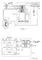
- the vehicle braking apparatus is composed of a hydraulic boost unit 1 and brake lines 2 going to the wheel brake, such as a caliper 3 located at the rotor 4, of a vehicle wheel.
- the total vehicle braking apparatus is comprised of the standard base braking components and a) an electronic controller 16, b) a wheel speed sensor 18 mounted at the wheel near c) an excitor ring 19, and d) a modulator assembly 10 described by the following mechanical relationships: 1) a DC motor 12 drives a gear train 24, turning a ball screw actuator 14, which is composed of a linear ball screw and nut; 2) as the linear ball screw rotates, the nut is moved either forward or backward; 3) when the DC motor drives the linear ball screw in the apply direction, the nut moves forward and a piston 22 is applied toward the top of travel; 4) a check ball 20 is unseated and held open when the piston 22 is at the top of travel; 5) when the DC motor 12 is reversed, the linear
- the antilock control apparatus in this embodiment is operative at all times while the vehicle is in operation.
- the excitor ring 19 rotates, causing the wheel speed sensor 18 to generate a signal proportional to the wheel speed.
- the signal is sent from the wheel speed sensor 18 to the electronic controller 16 for processing.
- the ball screw actuator 14, as shown in FIGURE 1 is in the passive mode with check ball 20 held open by the piston 22 at the top of travel.
- the hydraulic fluid can pass through the brake line 2 past the check ball 20 and through to the (wheel brake) caliper 3.
- the antilock control apparatus is said to be transparent during normal braking.
- the antilock control apparatus detects incipient wheel lockup based upon the dynamic parameters of vehicle wheel slip and wheel deceleration.
- the information from the wheel speed sensor 18 is used by the electronic controller 16 to calculate wheel slip and acceleration.
- the electronic controller 16 Upon detecting an incipient lock condition, indicated by high wheel deceleration and/or more particular to this invention excessive wheel slip, the electronic controller 16 initiates antilock activity.
- the electric controller 16 commands the DC motor 12 to reverse the ball screw actuator 14, causing the piston 22 to retract and the check ball 20 to seat, isolating the hydraulic boost unit 1 of the hydraulics from the wheel brake. As the piston 22 retracts, pressure at the wheel brake is relieved, allowing the wheel to begin to reaccelerate toward recovery.
- the electric controller 16 commands the DC motor 12 to reapply pressure, causing the ball screw actuator 14 to move forward, applying the piston 22 and returning fluid back to the (wheel brake) caliper 3. Wheel brake pressure is then increased toward the optimal pressure for the road surface. When the wheel again begins to approach lock, the wheel cycle process is repeated.
- a wheel cycle is defined as beginning with the detection of incipient lock and the subsequent release of pressure and ending when the pressure has been reapplied to the point just prior to incipient lock.
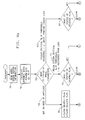
- the electronic controller 16 Based on the stated relationship between motor current, I, and wheel brake pressure, P, the electronic controller 16 implements instructions to achieve the desired wheel brake pressure. As shown in FIGURE 2, the electronic controller 16 consists of a) a common digital computer composed of read-only memory (ROM) 25, random access memory (RAM) 26, a power supply device (PSD) 28, an instruction processing architecture embodied in the central processing unit (CPU) 29, and input/output circuitry (I/O) 30 which interface to the b) motor driver circuit 31 and c) wheel speed sensor buffer circuit 32.
- ROM read-only memory
- RAM random access memory
- PSD power supply device
- I/O input/output circuitry
- the ROM 25 contains the instructions necessary to implement the algorithm diagrammed in FIGURES 3 and 4. It should be noted that in describing the functions of the algorithm encoded in the ROM, references to tasks which have been detailed as flow diagram function blocks will be designated by ⁇ nn ⁇ where nn is the diagram reference number and ⁇ ⁇ indicates that the concept described by the particular flow diagram function block text is being referenced.
- the text in the flow diagram function block is intended to describe the general task or process being executed by the electronic controller 16 at that point. The text does not represent the actual ROM instructions. It is recognized that there are a variety of known information-processing languages available to one skilled in the art to construct the actual instructions necessary to accomplish the tasks described by the text in the flow diagram function blocks.
- the electronic controller 16 When the antilock control apparatus is powered-up, via the vehicle ignition or other means, the electronic controller 16 will begin executing the instructions encoded in ROM 25. As shown in FIGURE 3, the electronic controller 16 will first perform system initialization ⁇ 35 ⁇ , which entails clearing registers, initializing specific RAM variables to calibrated values, stabilizing voltage levels at the I/O 30 and other basic functions of the digital computer.
- the system initialization process also includes insuring the ball screw actuator 14 is in the passive, or as earlier described, the transparent, mode shown in FIGURE 1.
- the ball screw actuator 14 is said to be transparent to the base braking functionality of the vehicle while the check ball 20 is unseated and is held open by the piston 22, allowing hydraulic boost unit 1 to reach the wheel brake.
- the electronic controller 16 will enable the control cycle interrupt ⁇ 36 ⁇ .
- the control cycle interrupt provides a means for accurately calculating the dynamic wheel parameters of wheel slip and acceleration by insuring that the time between calculations is fixed at a value such as 5 msec.
- the electronic controller 16 proceeds through the major loop referred to as the "control cycle".
- the electronic controller 16 performs both brake control processing tasks ⁇ 38 ⁇ and background tasks ⁇ 39 ⁇ .
- the brake control tasks include: reading and processing the wheel speed and DC motor signal information, determining whether antilock control is necessary, and performing antilock control functions as needed. Whether or not antilock control is required, the electronic controller 16 always evaluates wheel speed and calculates the dynamic wheel parameters.
- the electronic controller 16 After executing the brake control tasks, the electronic controller 16 proceeds to the background tasks ⁇ 39 ⁇ .
- the background tasks consist of diagnostic self-check activities and communication with off-board devices such as other vehicle controllers or service tools. All of these control cycle tasks are performed once every control cycle interrupt.
- the electronic controller 16 executes the brake control functions ⁇ 38 ⁇ and background tasks ⁇ 39 ⁇ . Thus, every control cycle, the electronic controller 16 evaluates the need for antilock activities, performs these activities as needed, and carries out diagnostic and off-board communications activities.
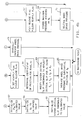
- FIGURE 4 the steps necessary to implement the general brake control functions ⁇ 38 ⁇ are detailed.
- the electronic controller 16 When the driver of the vehicle begins braking, fluid is applied to the wheel brake. As the wheel brake pressure increases, the wheel begins to decelerate.
- the electronic controller 16 is operative at all times, and executes the instructions, encoded in ROM 25, within the confines of the control cycle interrupt.
- the electronic controller 16 upon receiving a control cycle interrupt, proceeds to read the wheel speed sensor information ⁇ 50 ⁇ and calculate the dynamic wheel parameters of wheel slip and acceleration ⁇ 51 ⁇ . While the wheel brake pressure is at a value substantially below the pressure required to produce critical slip for the road surface, the status of the dynamic parameters ⁇ 52 ⁇ will indicate antilock control is not necessary ⁇ 53 ⁇ .
- the electronic controller 16 subsequently clears the release and reapply flags ⁇ 55 ⁇ , initializes the reference pressure value, P m , to a calibrated value ⁇ 57 ⁇ , initializes the detected surface coefficient, r , to a calibrated value ⁇ 59 ⁇ and initializes the system slip threshold to a calibrated value ⁇ 61 ⁇ .
- the system slip threshold is used at step ⁇ 52 ⁇ to determine whether an incipient lock condition exists.
- the electronic controller 16 continues the control cycle, proceeding to the background tasks. Since no antilock activities were initiated, the ball screw actuator 14 remains in the transparent mode. Given that the driver of the vehicle continues to apply the brakes, wheel brake pressure increases toward, and soon surpasses, the ideal pressure for the road surface.
- the electronic controller 16 again reads the wheel speed information ⁇ 50 ⁇ , calculates wheel slip and acceleration ⁇ 51 ⁇ , and evaluates the status of the dynamic parameters ⁇ 52 ⁇ .
- the dynamic parameters indicate an incipient lock condition ⁇ 63 ⁇ . This condition is typified by wheel slip exceeding the system slip threshold.
- the electronic controller 16 first evaluates the status of the release flag ⁇ 65 ⁇ , which, based upon the prior control cycle activity, is clear. Note that whenever the release flag is clear, it is indicating that the system was not performing a release during the prior control cycle.
- the electronic controller 16 stores the most recent commanded pressure, P m , which is the reference pressure ⁇ 69 ⁇ . This reference pressure is the maximum wheel brake pressure achieved during the wheel cycle, and represents the pressure required to produce incipient wheel lock. Due to the mechanical relationships previously related, the wheel brake pressure is proportional to the motor current.
- the motor current draw, I s as sensed by the electronic controller 16 through the motor driver circuit 31, can be considered representative of actual wheel brake pressure, P m , and is stored as such.
- the ball screw actuator 14 is in the transparent mode prior to initiating antilock activities. Due to this feature, a calibrated value has been stored as P m for this first wheel cycle. The calibrated value for P m was established during the previous control cycle when antilock control activity was not required (flow diagram path ⁇ 52 ⁇ - ⁇ 53 ⁇ - ⁇ 55 ⁇ - ⁇ 57 ⁇ - ⁇ 59 ⁇ - ⁇ 61 ⁇ ). Also, a calibrated value for the road surface coefficient, r , has been stored. This is because, in this embodiment, the calculation of r is dependent upon P m , as will be detailed later. Since P m has been set to a default value, it follows that r must also be established at some default value.
- the system slip threshold which is dependent upon r , has also been set to a calibration value.
- the system slip threshold is used at step ⁇ 52 ⁇ to indicate when an incipient wheel lock condition exists.
- the ball screw actuator 14 is no longer transparent.
- the DC motor 12 will now be driving the ball screw actuator 14.
- the actual value of I s rather than a calibrated value, is stored in P m during later wheel cycles.
- the system can calculate road surface coefficient, r , and from this modify the system slip threshold to reflect the actual critical slip for the surface.
- the electronic controller 16 commands the ball screw actuator 14 to release wheel brake pressure ⁇ 71 ⁇ . This is accomplished by rotating the DC motor 12 in the reverse direction, which retracts the piston 22, seats the check ball 20, isolates the wheel brake from the hydraulic boost unit 1 and relieves pressure at the wheel brake.
- the electronic controller 16 completes the control cycle by proceeding to execute the background tasks.
- the electronic controller 16 continues reading wheel speed information ⁇ 50 ⁇ , calculating dynamic wheel parameters ⁇ 51 ⁇ , and evaluating the status of these wheel parameters ⁇ 52 ⁇ every interrupt control cycle. While the wheel is still tending to lock ⁇ 63 ⁇ , the release flag remains set (as it was set during the first time through this path) and the electronic controller 16 proceeds from determining the status of the release flag ⁇ 65 ⁇ directly to relieving wheel brake pressure ⁇ 71 ⁇ , and does not disturb the stored value of P m .
- the electronic controller 16 proceeds, as usual, through steps ⁇ 50 ⁇ , ⁇ 51 ⁇ and ⁇ 52 ⁇ , and determines that the dynamic parameters indicate the wheel is now substantially recovered ⁇ 73 ⁇ . Substantial recovery occurs when wheel slip is below the system slip threshold. Again, recall that until the electronic controller 16 is able to affirmatively establish a system slip threshold value, the default value established during path ⁇ 63 ⁇ - ⁇ 65 ⁇ - ⁇ 67 ⁇ - ⁇ 69 ⁇ - ⁇ 71 ⁇ is used.
- the electronic controller 16 next evaluates the status of the reapply flag ⁇ 75 ⁇ , which, based upon the prior control cycle activity, is clear. Keeping with the purpose of the reapply and release flags, the reapply flag is set and the release flag is cleared ⁇ 77 ⁇ .
- the electronic controller 16 determines the coefficient of friction for the operating surface ⁇ 81 ⁇ , in a manner such as illustrated in Research Disclosure, No. 295100, page 924, November 1988. This is done by first weighting P m , the reference pressure, as being indicative of either a high, medium or low coefficient surface. If P m , the maximum brake pressure achieved during the wheel cycle, is a large value (for example ⁇ 8274 kPa [1200 p.s.i.]), it is considered indicative of operation on a high coefficient of friction surface and is weighted with a value representative of a high mu surface (0.8 - 1.0).
- a moderate (4137 - 8274 kPa [600 - 1200 p.s.i.]) value of P m is considered indicative of a medium coefficient surface and is weighted as such (0.4 - 0.8), while a low value of P m ( ⁇ 4137 kPa [600 p.s.i.]) is indicative of a low coefficient of friction and is weighted with a low mu surface value (0.05 - 0.4).
- the peak wheel reacceleration is likewise weighted.
- a high peak reacceleration ( ⁇ 6 g's where g is the acceleration due to gravity) is considered indicative of a high coefficient of friction and is correspondingly weighted to represent a high mu surface (0.8 - 1.0)
- a moderate (2 - 6 g's) peak reacceleration is indicative of a medium coefficient and is weighted accordingly (0.4 - 0.8)
- a small ( ⁇ 2 g's) peak reacceleration is indicative of a low coefficient surface and is weighted to represent a low mu surface (0.05 - 0.4).
- the surface adjustment factor is a real number which, based on r , is either positive or negative. This allows for a multiple of the measured surface coefficient, r , to be added to or subtracted from s d to arrive at the proper value for s c .
- the system slip threshold is adjusted up or down, depending upon the operating surface, to reflect the actual critical slip value for the road.
- the electronic controller 16 initiates the reapply by commanding the DC motor 12 to produce the torque necessary to achieve a significant fraction of the previously stored reference pressure, P m .
- P m the previously stored reference pressure
- braking efficiency is maximized by striving to brake at or near the pressure required to produce critical wheel slip. Therefore, the initial reapply proceeds rapidly to a significant fraction of P m .
- the electronic controller 16 proceeds along the flow path ⁇ 50 ⁇ - ⁇ 51 ⁇ - ⁇ 52 ⁇ - ⁇ 75 ⁇ directly to ⁇ 79 ⁇ , as the reapply flag has been set.
- the system slip threshold has been modified to mimic the actual critical slip value for the road surface, once wheel brake pressure has been increased to the point that this value of slip is present at the wheel, an incipient lock condition will be detected. Because the system detects an incipient lock when wheel slip has exceeded the system slip threshold, the modification of the slip threshold to mimic the actual critical slip enables the system to detect an incipient lock condition as it is actually occurring. Without such modification, the system risks either over or under braking the wheel depending on if the system slip threshold is higher or lower, respectively, than the actual critical slip value. With the detection of the incipient lock, the electronic controller 16 begins executing path ⁇ 52 ⁇ - ⁇ 63 ⁇ again. Proceeding as described before, the status of the release flag will be clear ⁇ 65 ⁇ .
- the release and reapply flags are updated ⁇ 67 ⁇ and the maximum wheel brake pressure achieved during the completed wheel cycle is stored in P m ⁇ 69 ⁇ .
- Brake pressure is relieved ⁇ 71 ⁇ , and continues to be relieved (path ⁇ 52 ⁇ - ⁇ 63 ⁇ - ⁇ 65 ⁇ - ⁇ 71 ⁇ ) until the incipient lock condition is remedied.
- the electronic controller 16 will again proceed along path ⁇ 52 ⁇ - ⁇ 73 ⁇ - ⁇ 75 ⁇ - ⁇ 77 ⁇ , recalculating the coefficient of friction for the road surface ⁇ 81 ⁇ and modifying the system slip threshold to accurately mimic the actual critical slip value for the road surface ⁇ 83 ⁇ .
- the electronic controller 16 is able to determine the unique critical slip value at which a lock condition will occur on the given operating surface and, by alternately releasing and reapplying wheel brake pressure, based upon the determined critical slip value, maintain wheel slip substantially at the value of slip which produces maximum vehicle brake efficiency.
Landscapes
- Engineering & Computer Science (AREA)
- Transportation (AREA)
- Mechanical Engineering (AREA)
- Microelectronics & Electronic Packaging (AREA)
- Regulating Braking Force (AREA)
Applications Claiming Priority (2)
| Application Number | Priority Date | Filing Date | Title |
|---|---|---|---|
| US337726 | 1989-04-13 | ||
| US07/337,726 US4916619A (en) | 1989-04-13 | 1989-04-13 | Adaptive wheel slip threshold |
Publications (2)
| Publication Number | Publication Date |
|---|---|
| EP0392686A2 true EP0392686A2 (fr) | 1990-10-17 |
| EP0392686A3 EP0392686A3 (fr) | 1992-01-22 |
Family
ID=23321752
Family Applications (1)
| Application Number | Title | Priority Date | Filing Date |
|---|---|---|---|
| EP19900303094 Withdrawn EP0392686A3 (fr) | 1989-04-13 | 1990-03-22 | Dispositif et méthode de commande antiblocage |
Country Status (4)
| Country | Link |
|---|---|
| US (1) | US4916619A (fr) |
| EP (1) | EP0392686A3 (fr) |
| JP (1) | JPH0367766A (fr) |
| CA (1) | CA2010642C (fr) |
Cited By (8)
| Publication number | Priority date | Publication date | Assignee | Title |
|---|---|---|---|---|
| WO1992007741A1 (fr) * | 1990-11-02 | 1992-05-14 | Robert Bosch Gmbh | Systeme d'antiblocage des roues |
| EP0488037A1 (fr) * | 1990-11-27 | 1992-06-03 | Mazda Motor Corporation | Système de freinage anti-patinage pour véhicules |
| EP0533436A3 (en) * | 1991-09-17 | 1993-09-15 | Honda Giken Kogyo Kabushiki Kaisha | Method of and system for controlling brakes |
| EP0537995B1 (fr) * | 1991-10-14 | 1997-01-22 | Honda Giken Kogyo Kabushiki Kaisha | Méthode et système pour commander des freins |
| FR2770188A1 (fr) * | 1997-10-24 | 1999-04-30 | Siemens Ag | Procede de freinage a actionnement electrique d'un vehicule automobile et systeme de freinage a actionnement electrique |
| EP0950591A3 (fr) * | 1991-10-08 | 2000-03-15 | Honda Giken Kogyo Kabushiki Kaisha | Méthode pour le contrôle des freins |
| EP2450247A1 (fr) * | 2010-11-05 | 2012-05-09 | Honda Motor Co., Ltd. | Système de commande de freinage anti-blocage |
| EP2514640A1 (fr) * | 2001-12-21 | 2012-10-24 | Kabushiki Kaisha Bridgestone | Procédé et appareil pour l'estimation de l'état de la route et de l'état de fonctionnement de pneumatiques et de l'abs et de commande de voiture faisant usage de celui-ci |
Families Citing this family (27)
| Publication number | Priority date | Publication date | Assignee | Title |
|---|---|---|---|---|
| DE3938444C2 (de) * | 1989-11-18 | 1998-10-01 | Daimler Benz Ag | Verfahren zur Regelung des Antriebsschlupfes |
| DE4000212A1 (de) * | 1990-01-05 | 1991-07-11 | Lucas Ind Plc | Verfahren zum blockiergeschuetzten bremsen eines motorrades und zum bestimmen des haftbeiwertes |
| US5147115A (en) * | 1990-04-16 | 1992-09-15 | General Motors Corporation | Adaptive release apply algorithm |
| JP2907497B2 (ja) * | 1990-06-21 | 1999-06-21 | マツダ株式会社 | 車両のトラクション制御装置 |
| JPH04110264A (ja) * | 1990-08-30 | 1992-04-10 | Sumitomo Electric Ind Ltd | 学習補正機能を備えたアンチロック制御装置 |
| DE4031707C2 (de) * | 1990-10-06 | 2000-08-03 | Continental Teves Ag & Co Ohg | Schaltungsanordnung für eine Bremsanlage mit Blockierschutz- oder Antriebsschlupfregelung |
| US5259667A (en) * | 1990-11-29 | 1993-11-09 | Mazda Motor Corporation | Anti-skid brake system for an automotive vehicle |
| DE4102301C1 (fr) * | 1991-01-26 | 1992-06-11 | Mercedes-Benz Aktiengesellschaft, 7000 Stuttgart, De | |
| US5173860A (en) * | 1991-01-28 | 1992-12-22 | General Motors Corporation | Reference speed determination for an antilock brake system |
| US5281009A (en) * | 1992-08-19 | 1994-01-25 | General Motors Corporation | Antilock brake system with closed loop control of hold during release |
| US5450324A (en) * | 1993-01-07 | 1995-09-12 | Ford Motor Company | Electric vehicle regenerative antiskid braking and traction control system |
| JP3353846B2 (ja) * | 1993-04-16 | 2002-12-03 | マツダ株式会社 | 車両のアンチスキッドブレーキ装置 |
| US5487594A (en) * | 1994-11-30 | 1996-01-30 | Alliedsignal Inc. | Method for updating a wheel reference value by assessing proximity for the braking power curve peak |
| US5646848A (en) * | 1995-08-09 | 1997-07-08 | General Motors Corporation | Method for proportionally controlling the brakes of a vehicle based on tire deformation |
| US5646849A (en) * | 1995-08-09 | 1997-07-08 | General Motors Corporation | Method for proportionally controlling the brakes of a vehicle based on front and rear wheel speeds |
| US5511859A (en) * | 1995-08-25 | 1996-04-30 | General Motors Corporation | Regenerative and friction brake blend control |
| US5870550A (en) * | 1996-02-26 | 1999-02-09 | Network Engineering Software | Web server employing multi-homed, moldular framework |
| US6513886B1 (en) | 1996-05-07 | 2003-02-04 | General Motors Corporation | Brake system control in which update of wheel speed normalization factors is selectively inhibited |
| WO1999033688A2 (fr) * | 1997-12-30 | 1999-07-08 | Kelsey-Hayes Company | Algorithme pour la prevention de la reduction intempestive de la vitesse de la roue sur une surface a faible coefficient de frottement |
| US6292735B1 (en) | 1998-08-10 | 2001-09-18 | Ford Global Technologies, Inc. | Wheelslip regulating brake control |
| US6370467B1 (en) | 1998-08-10 | 2002-04-09 | Ford Global Technologies, Inc. | Method of calculating optimal wheelslips for brake controller |
| JP3371826B2 (ja) * | 1998-10-22 | 2003-01-27 | トヨタ自動車株式会社 | 制動トルク制御装置 |
| WO2002074595A1 (fr) * | 2001-03-15 | 2002-09-26 | Continental Teves Ag & Co. Ohg | Procede de commande et/ou de regulation de l'etablissement de la puissance de freinage lors d'un freinage total a un coefficient de frottement eleve |
| US7853389B2 (en) * | 2007-10-29 | 2010-12-14 | Ford Global Technologies, Llc | Traction control for performance and demonstration spin |
| JP2008170009A (ja) * | 2008-03-04 | 2008-07-24 | Koyo Sealing Techno Co Ltd | オイルシール |
| US8706378B2 (en) | 2011-11-28 | 2014-04-22 | Toyota Motor Engineering & Manufacturing North America, Inc. | Systems and methods for determining road mu and drive force |
| US9387844B2 (en) * | 2014-11-24 | 2016-07-12 | Toyota Motor Engineering & Manufacturing North America, Inc. | Environment-based anti-lock braking system |
Family Cites Families (15)
| Publication number | Priority date | Publication date | Assignee | Title |
|---|---|---|---|---|
| US3717384A (en) * | 1971-03-15 | 1973-02-20 | Gen Motors Corp | Anti-lock brake control system |
| US4530059A (en) * | 1982-04-30 | 1985-07-16 | Lucas Industries Public Limited Company | Vehicle anti-lock breaking control |
| JPS6035646A (ja) * | 1983-08-09 | 1985-02-23 | Nippon Denso Co Ltd | アンチスキツド制御装置 |
| EP0152602B1 (fr) * | 1983-12-16 | 1987-07-22 | Robert Bosch Gmbh | Procédé pour déterminer une valeur de glissement optimale |
| DE3500745A1 (de) * | 1985-01-11 | 1986-07-17 | Alfred Teves Gmbh, 6000 Frankfurt | Verfahren und schaltungsanordnung zur anpassung der schlupfregelung an den momentanen reibwert |
| JPS6229461A (ja) * | 1985-08-01 | 1987-02-07 | Toyota Motor Corp | 車両の加速スリツプ制御装置 |
| DE3535843A1 (de) * | 1985-10-08 | 1987-04-16 | Bosch Gmbh Robert | Verfahren zur fortlaufenden bestimmung des kraftschlussbeiwerts (my) |
| JPS6285146A (ja) * | 1985-10-11 | 1987-04-18 | Nissan Motor Co Ltd | 車両のトラクシヨンコントロ−ル装置 |
| US4664453A (en) * | 1985-10-21 | 1987-05-12 | General Motors Corporation | Anti-lock brake control system |
| JPH0688532B2 (ja) * | 1985-12-27 | 1994-11-09 | 曙ブレーキ工業株式会社 | アンチスキツド制御方法 |
| DE3717531C2 (de) * | 1986-05-30 | 1993-12-23 | Tokico Ltd | Schaltungsanordnung zum Bestimmen der Referenzgeschwindigkeit in einer blockiergeschützten Fahrzeug-Bremsanlage |
| US4779696A (en) * | 1986-07-24 | 1988-10-25 | Mazda Motor Corporation | Vehicle slip control apparatus |
| JP2638785B2 (ja) * | 1986-09-06 | 1997-08-06 | 日産自動車株式会社 | アンチスキツド制御装置 |
| US4750124A (en) * | 1986-11-19 | 1988-06-07 | General Motors Corporation | Anti-lock brake control system |
| US4818037A (en) * | 1988-05-16 | 1989-04-04 | Hughes Aircraft Company | Method for estimating reference speed and acceleration for traction and anti-skid braking control |
-
1989
- 1989-04-13 US US07/337,726 patent/US4916619A/en not_active Expired - Lifetime
-
1990
- 1990-02-22 CA CA002010642A patent/CA2010642C/fr not_active Expired - Fee Related
- 1990-03-22 EP EP19900303094 patent/EP0392686A3/fr not_active Withdrawn
- 1990-04-13 JP JP2099172A patent/JPH0367766A/ja active Pending
Cited By (10)
| Publication number | Priority date | Publication date | Assignee | Title |
|---|---|---|---|---|
| US5312170A (en) * | 1990-02-11 | 1994-05-17 | Robert Bosch Gmbh | Anti-lock brake system |
| WO1992007741A1 (fr) * | 1990-11-02 | 1992-05-14 | Robert Bosch Gmbh | Systeme d'antiblocage des roues |
| EP0488037A1 (fr) * | 1990-11-27 | 1992-06-03 | Mazda Motor Corporation | Système de freinage anti-patinage pour véhicules |
| EP0533436A3 (en) * | 1991-09-17 | 1993-09-15 | Honda Giken Kogyo Kabushiki Kaisha | Method of and system for controlling brakes |
| EP0656291A1 (fr) * | 1991-09-17 | 1995-06-07 | Honda Giken Kogyo Kabushiki Kaisha | Méthode et système pour commander les freins |
| EP0950591A3 (fr) * | 1991-10-08 | 2000-03-15 | Honda Giken Kogyo Kabushiki Kaisha | Méthode pour le contrôle des freins |
| EP0537995B1 (fr) * | 1991-10-14 | 1997-01-22 | Honda Giken Kogyo Kabushiki Kaisha | Méthode et système pour commander des freins |
| FR2770188A1 (fr) * | 1997-10-24 | 1999-04-30 | Siemens Ag | Procede de freinage a actionnement electrique d'un vehicule automobile et systeme de freinage a actionnement electrique |
| EP2514640A1 (fr) * | 2001-12-21 | 2012-10-24 | Kabushiki Kaisha Bridgestone | Procédé et appareil pour l'estimation de l'état de la route et de l'état de fonctionnement de pneumatiques et de l'abs et de commande de voiture faisant usage de celui-ci |
| EP2450247A1 (fr) * | 2010-11-05 | 2012-05-09 | Honda Motor Co., Ltd. | Système de commande de freinage anti-blocage |
Also Published As
| Publication number | Publication date |
|---|---|
| EP0392686A3 (fr) | 1992-01-22 |
| CA2010642A1 (fr) | 1990-10-13 |
| JPH0367766A (ja) | 1991-03-22 |
| CA2010642C (fr) | 1994-07-26 |
| US4916619A (en) | 1990-04-10 |
Similar Documents
| Publication | Publication Date | Title |
|---|---|---|
| US4916619A (en) | Adaptive wheel slip threshold | |
| US4881784A (en) | ABS pressure apply algorithm | |
| US4917445A (en) | ABS variant nominal hold pressure | |
| CA2039808C (fr) | Limiteur de lacet sur frein antiblocage | |
| EP0397328B1 (fr) | Appareil et procédé de commande d'entraînement de véhicule | |
| US6890041B1 (en) | Antilock brake systems employing a sliding mode observer based estimation of differential wheel torque | |
| US6125318A (en) | Slip ratio antiskid controller using mu/slip ratio generated velocity reference | |
| EP0397330B1 (fr) | Procédé de commande d'entraînement de véhicule | |
| EP0448145A2 (fr) | Méthode pour commander la vitesse d'un moteur | |
| US4828334A (en) | Antilock brake control system | |
| JPH07144630A (ja) | 車両の制動力を最大にするための方法とその装置 | |
| US5315518A (en) | Method and apparatus for initializing antilock brake control on split coefficient surface | |
| US5273349A (en) | Antilock brake system with motor current control | |
| US5071199A (en) | Antilock brake system with motor current control | |
| EP0489451B1 (fr) | Système de réglage antiblocage avec un moyen de commande du courant du moteur | |
| EP0397329B1 (fr) | Appareil de commande d'entraînement de véhicule | |
| US4924394A (en) | Anti-skid braking system for automotive vehicle | |
| US5308153A (en) | Antilock brake system with closed loop apply bump | |
| US4849890A (en) | Anti-skid braking system for automotive vehicle | |
| EP0459548B1 (fr) | Méthode et appareil pour commander la pression de freinage appliquée à un frein de véhicule | |
| JPS62166152A (ja) | 車両用アンチスキツド装置 | |
| CN117698727A (zh) | 一种车辆防滑控制方法、系统、终端及存储介质 | |
| JPH0747383B2 (ja) | アンチスキツド制御装置 | |
| JPH04228351A (ja) | 制動圧力を制限するための方法 | |
| JPH0674545U (ja) | アンチスキッド制御装置 |
Legal Events
| Date | Code | Title | Description |
|---|---|---|---|
| PUAI | Public reference made under article 153(3) epc to a published international application that has entered the european phase |
Free format text: ORIGINAL CODE: 0009012 |
|
| AK | Designated contracting states |
Kind code of ref document: A2 Designated state(s): DE FR GB IT |
|
| PUAL | Search report despatched |
Free format text: ORIGINAL CODE: 0009013 |
|
| AK | Designated contracting states |
Kind code of ref document: A3 Designated state(s): DE FR GB IT |
|
| 17P | Request for examination filed |
Effective date: 19920312 |
|
| 17Q | First examination report despatched |
Effective date: 19930524 |
|
| STAA | Information on the status of an ep patent application or granted ep patent |
Free format text: STATUS: THE APPLICATION IS DEEMED TO BE WITHDRAWN |
|
| 18D | Application deemed to be withdrawn |
Effective date: 19931005 |