EP0399254A2 - Transducteur magnéto-électrique - Google Patents
Transducteur magnéto-électrique Download PDFInfo
- Publication number
- EP0399254A2 EP0399254A2 EP90108295A EP90108295A EP0399254A2 EP 0399254 A2 EP0399254 A2 EP 0399254A2 EP 90108295 A EP90108295 A EP 90108295A EP 90108295 A EP90108295 A EP 90108295A EP 0399254 A2 EP0399254 A2 EP 0399254A2
- Authority
- EP
- European Patent Office
- Prior art keywords
- magneto
- electric transducer
- fingers
- lead frame
- ics
- Prior art date
- Legal status (The legal status is an assumption and is not a legal conclusion. Google has not performed a legal analysis and makes no representation as to the accuracy of the status listed.)
- Withdrawn
Links
Images



Classifications
-
- G—PHYSICS
- G01—MEASURING; TESTING
- G01R—MEASURING ELECTRIC VARIABLES; MEASURING MAGNETIC VARIABLES
- G01R33/00—Arrangements or instruments for measuring magnetic variables
- G01R33/02—Measuring direction or magnitude of magnetic fields or magnetic flux
- G01R33/06—Measuring direction or magnitude of magnetic fields or magnetic flux using galvano-magnetic devices
- G01R33/07—Hall effect devices
Definitions
- the present invention relates to a magneto-electric transducer for detecting N and S poles.
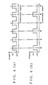
- magneto-electric transducers Conventionally, there have been known as magneto-electric transducers, alternating magnetic field type devices having an operating point near a zero point of the intensity of the magnetic field for detecting the transition of the magnetic field from N to S or from S to N. Also is known a uni-directional magnetic field type magneto-electric transducer which consists of a Hall IC mounted on a major surface of a base member included in a lead frame as illustrated in Figures 5(a) and (b) showing both of its major surfaces, and has an operating point at a certain positive level of the intensity of a magnetic field so as to detect the presence of an N pole as indicated in Figure 4(b).
- a primary object of the present invention is to provide a magneto-electric transducer which can detect the presence of either N or S pole at the same time by using a relatively simple structure.
- a second object of the present invention is to provide a magneto-electric transducer which can detect the presence of either N or S pole by using a relatively compact structure.
- a magneto-electric transducer comprising: a base member; a pair of magneto-electric transducer ICs mounted on the base member adjacent to each other; and lead means for connecting leads of the magneto-electric transducer ICs to an external circuit.
- the base member consists of a planar member, and the magneto-electric transducer ICs are mounted on either major surface of the base member.
- the lead means may consist of a plurality of fingers of a lead frame, and the base member may be formed in an extension of one of the fingers of the lead frame.
- a pair of additional fingers of the lead frame extend in parallel with the first mentioned finger in such a manner that the magneto-electric transducer ICs may be connected to the lead means via these fingers in a mutually parallel relationship.
- N and S poles can be detected with an extremely simple structure. Therefore, the cost can be significantly reduced as compared with designing a special IC, and the size of the transducer can be significantly reduced as compared with forming a bidirectional magnetic field type transducer by using an external circuit or a specialized IC.
- FIGS 1(a) and (b) are perspective views showing a preferred embodiment of the magneto-electric transducer according to the present invention from two different directions.
- This magneto-electric transducer includes three fingers 1 through 3 of a lead frame, and a Hall IC 4 having a structure which is described hereinafter is mounted on a base 1a of one of the fingers 1 of the lead frame with its three terminals connected to the three fingers 1 through 3 of the lead frame, respectively, by wire bonding.
- Another Hall IC 5 having a similar structure is mounted on the reverse surface of the base 1a of the first finger 1 of the lead frame, and its terminals are likewise connected to the three fingers 1 through 3 of the lead frame, respectively, by wire boding.
- a magneto-electric transducer is formed by mounting the Hall ICs 4 and 5 on either major surface of the base 1a of the first finger 1 of the lead frame, and encapsulating them in a resin molding 6 as indicated by the broken lines in Figures 1(a) and 1(b).
- Figure 2 shows a circuit diagram showing the connection between the Hall ICs 4 and 5 and the different fingers 1 through 3 of the lead frame.
- the ICs 4 and 5 are each provided with a Hall device 4b or 5b and a voltage regulating circuit 4a or 5a so that a constant voltage may be applied to each of the Hall devices 4b and 5b.
- the Hall devices 4b and 5b are adapted to detect the intensity of magnetic fields of different polarities, and their outputs are supplied to Schmitt trigger circuits 4d and 5d via amplifiers 4c and 5c, respectively.
- the Schmitt trigger circuits 4d and 5d discriminate the outputs from the amplifiers 4c and 5c according to a certain threshold level, and their outputs are supplied to an external circuit not shown in the drawings via output transistors 4e and 5e, respectively.
- the collectors of the output transistors 4e and 5e are commonly connected to the second finger 2 of the lead frame, and the positive and negative power inputs to the Hall ICs 4 and 5 are also commonly connected to the third and first fingers 3 and 1 of the lead frame, respectively.
Landscapes
- Physics & Mathematics (AREA)
- Condensed Matter Physics & Semiconductors (AREA)
- General Physics & Mathematics (AREA)
- Measuring Magnetic Variables (AREA)
- Hall/Mr Elements (AREA)
- Transmission And Conversion Of Sensor Element Output (AREA)
Applications Claiming Priority (2)
| Application Number | Priority Date | Filing Date | Title |
|---|---|---|---|
| JP61302/89U | 1989-05-26 | ||
| JP6130289U JPH02150585U (fr) | 1989-05-26 | 1989-05-26 |
Publications (2)
| Publication Number | Publication Date |
|---|---|
| EP0399254A2 true EP0399254A2 (fr) | 1990-11-28 |
| EP0399254A3 EP0399254A3 (fr) | 1992-01-15 |
Family
ID=13167255
Family Applications (1)
| Application Number | Title | Priority Date | Filing Date |
|---|---|---|---|
| EP19900108295 Withdrawn EP0399254A3 (fr) | 1989-05-26 | 1990-05-02 | Transducteur magnéto-électrique |
Country Status (2)
| Country | Link |
|---|---|
| EP (1) | EP0399254A3 (fr) |
| JP (1) | JPH02150585U (fr) |
Cited By (2)
| Publication number | Priority date | Publication date | Assignee | Title |
|---|---|---|---|---|
| GB2276246A (en) * | 1990-10-27 | 1994-09-21 | Birt Electronic Systems Limite | Hall effect sensor |
| US6800818B2 (en) | 2000-05-19 | 2004-10-05 | I.M.A. Industria Macchine Automatiche S.P.A. | Distributor unit |
Family Cites Families (3)
| Publication number | Priority date | Publication date | Assignee | Title |
|---|---|---|---|---|
| US3909711A (en) * | 1971-07-28 | 1975-09-30 | Sandco Ltd | Transducer for sensing a variation of a magnetic field on a conveyor belt |
| JPS5679270A (en) * | 1979-11-30 | 1981-06-29 | Toshiba Corp | Magnetic polarity-measuring apparatus |
| DE3435455A1 (de) * | 1984-09-27 | 1986-03-27 | Nukem Gmbh, 6450 Hanau | Vorrichtung mit zwei hallgeneratoren zur messung der gradienten magnetischer felder |
-
1989
- 1989-05-26 JP JP6130289U patent/JPH02150585U/ja active Pending
-
1990
- 1990-05-02 EP EP19900108295 patent/EP0399254A3/fr not_active Withdrawn
Cited By (3)
| Publication number | Priority date | Publication date | Assignee | Title |
|---|---|---|---|---|
| GB2276246A (en) * | 1990-10-27 | 1994-09-21 | Birt Electronic Systems Limite | Hall effect sensor |
| GB2276246B (en) * | 1990-10-27 | 1995-03-15 | Birt Electronic Systems Limite | Hall effect sensors |
| US6800818B2 (en) | 2000-05-19 | 2004-10-05 | I.M.A. Industria Macchine Automatiche S.P.A. | Distributor unit |
Also Published As
| Publication number | Publication date |
|---|---|
| JPH02150585U (fr) | 1990-12-26 |
| EP0399254A3 (fr) | 1992-01-15 |
Similar Documents
| Publication | Publication Date | Title |
|---|---|---|
| US4066962A (en) | Metal detecting device with magnetically influenced Hall effect sensor | |
| US10274507B2 (en) | Stray-field robust, twist-insensitive magnetic speed sensors | |
| JPS63172957A (ja) | 歯車の歯センサー | |
| DE60236662D1 (de) | Inertialsensorvorrichtung mit einer vielzahl von ausgängen | |
| US4873448A (en) | Input circuit having a photo-coupler with bi-directional indicator | |
| JPH0979865A (ja) | 磁気検出センサ | |
| GB1510548A (en) | Positional transducers utilizing magnetic elements | |
| JPH03135722A (ja) | 回転センサ | |
| CN212932760U (zh) | 一种电流传感器 | |
| JPS6079281A (ja) | 磁気センサ | |
| JPH08279326A (ja) | 混成集積回路装置 | |
| JP2001091613A (ja) | 磁気センサ用マルチチップモジュール | |
| JPH08304479A (ja) | 電流スイッチ | |
| EP0399254A3 (fr) | Transducteur magnéto-électrique | |
| JPS62199678U (fr) | ||
| JPS6247730A (ja) | 位置検出装置 | |
| JP3604472B2 (ja) | 多点磁界測定装置 | |
| JPH06160499A (ja) | 磁気検出装置 | |
| JP3179417B2 (ja) | 強磁性物体通過センサ | |
| JPS6191716A (ja) | 座標読取装置 | |
| JPS6135718B2 (fr) | ||
| JPH06174490A (ja) | 磁気検出装置 | |
| JPS58166204A (ja) | 回転位置検出装置 | |
| JPS61108915A (ja) | 磁気センサ− | |
| JPH09230012A (ja) | 磁気センサ |
Legal Events
| Date | Code | Title | Description |
|---|---|---|---|
| PUAI | Public reference made under article 153(3) epc to a published international application that has entered the european phase |
Free format text: ORIGINAL CODE: 0009012 |
|
| 17P | Request for examination filed |
Effective date: 19900528 |
|
| AK | Designated contracting states |
Kind code of ref document: A2 Designated state(s): AT BE CH DE DK ES FR GB GR IT LI NL SE |
|
| PUAL | Search report despatched |
Free format text: ORIGINAL CODE: 0009013 |
|
| AK | Designated contracting states |
Kind code of ref document: A3 Designated state(s): AT BE CH DE DK ES FR GB GR IT LI NL SE |
|
| STAA | Information on the status of an ep patent application or granted ep patent |
Free format text: STATUS: THE APPLICATION HAS BEEN WITHDRAWN |
|
| 18W | Application withdrawn |
Withdrawal date: 19920317 |