EP0399450A2 - Metall-Giessystem - Google Patents
Metall-Giessystem Download PDFInfo
- Publication number
- EP0399450A2 EP0399450A2 EP90109675A EP90109675A EP0399450A2 EP 0399450 A2 EP0399450 A2 EP 0399450A2 EP 90109675 A EP90109675 A EP 90109675A EP 90109675 A EP90109675 A EP 90109675A EP 0399450 A2 EP0399450 A2 EP 0399450A2
- Authority
- EP
- European Patent Office
- Prior art keywords
- metal
- dish
- rate
- intermediate holding
- pouring
- Prior art date
- Legal status (The legal status is an assumption and is not a legal conclusion. Google has not performed a legal analysis and makes no representation as to the accuracy of the status listed.)
- Withdrawn
Links
Images


Classifications
-
- B—PERFORMING OPERATIONS; TRANSPORTING
- B22—CASTING; POWDER METALLURGY
- B22D—CASTING OF METALS; CASTING OF OTHER SUBSTANCES BY THE SAME PROCESSES OR DEVICES
- B22D11/00—Continuous casting of metals, i.e. casting in indefinite lengths
- B22D11/16—Controlling or regulating processes or operations
- B22D11/18—Controlling or regulating processes or operations for pouring
-
- B—PERFORMING OPERATIONS; TRANSPORTING
- B22—CASTING; POWDER METALLURGY
- B22D—CASTING OF METALS; CASTING OF OTHER SUBSTANCES BY THE SAME PROCESSES OR DEVICES
- B22D11/00—Continuous casting of metals, i.e. casting in indefinite lengths
- B22D11/008—Continuous casting of metals, i.e. casting in indefinite lengths of clad ingots, i.e. the molten metal being cast against a continuous strip forming part of the cast product
Definitions
- the present invention relates to a method and apparatus for the control of the rate of pouring of molten metal.
- a method for the control of the rate of flow of molten metal comprises the steps of measuring by first sensor means the thickness of metal poured onto a moving strip, comparing the measured thickness with a desired thickness stored in computer memory and control means, measuring the level of molten metal in intermediate holding dish means by second sensor means which is also linked to computer memory and control means, increasing or decreasing, as appropriate the rate of pour from holding furnace melting means to the intermediate holding dish means by signals from the computer control means to furnace pour rate control means in order to minimise the difference between the actual measured metal thickness of the strip and the desired thickness by adjustment of the molten metal level in the intermediate holding dish relative to pouring means in the holding dish.
- the intermediate holding dish means is maintained stationary and consists of a dish which has a relatively large surface area to volume ratio so that minor, short term fluctuations in metal flow from the holding furnace have a negligible effect on the level of molten metal in the dish.
- the control of metal flow from the intermediate holding dish via the pouring means is effected by varying the head of metal presented to and passing through a generally vertical pouring slot whose width is relatively small compared to its height. This has been found to provide much greater control of the rate of pouring than with known methods of pouring such as, for example, teeming over a relatively wide lip on the edge of a crucible.
- the intermediate holding dish may itself be moveable and used as a rate of pouring control by varying the apparent metal head presented to the pouring slot. This is effected by maintaining a substantially constant metal level and varying the height of the pouring slot in the dish relative to the constant metal level by tilting of the dish. In this way the pouring rate onto the strip, for example, may be increased or decreased.
- the constant metal level is maintained by varying the rate of pour from the holding furnace in response to signals from the second sensor means via the computer control means.
- Both the holding dish and holding furnance may be controlled by servo motors or by hydraulic means, for example.
- the first and second sensor means may be laser gauge probes.
- the parameter being measured is the total thickness of a strip on which metal is being cast, two interconnected probes may be used.
- apparatus for the control of the rate of flow of molten metal onto a moving strip comprises first sensor means for measuring the thickness of metal poured onto the strip, the first sensor means being linked to computer memory and control means for comparing the actual thickness of metal on the strip with a desired thickness stored in the computer memory to be achieved, second sensor means linked to the computer memory and control means to measure the level of molten metal in intermediate holding dish means, furnace melting means having servo control means to vary the rate of pour from the furnace, the rate of pour from the furnace melting means being responsive to signals from the computer control means to adjust the metal level in the intermediate holding dish means relative to pouring means therein.
- a melting and holding furnace 14 containing molten metal 16 is pivoted by a servo motor 18 about an axis 20 adjacent a pouring lip 22.
- the molten metal 16 is poured down a launder 24 into a stationary, intermediate holding dish 26.
- the molten metal flows out of the dish 26 via a slot 28 (see Figures 3 and 4 onto a spreader 30 and finally onto the strip 10 where it rapidly solidifies with the aid of quench sprays 32 as the coating 12.
- the thickness of the coated strip is measured by first sensor means which in this case comprises a pair of interlinked laser gauge probes 34.
- the probes 34 are linked 36 to computer memory and control means 38 which are also adapted to transmit signals 40 to second sensor means, which comprises a laser gauge probe 42, and to receive signals 44 therefrom.
- the computer control means 38 also transmits control signals 46 to a servo motor 18.
- the launder 24, dish 26 and spreader 30 are all enclosed within a heating chamber 48 which maintains a suitable temperature and protective atmosphere to prevent premature solidification and oxidation of the molten metal 16.
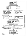
- molten metal is poured onto the strip 10 and soldifies as the coating 12; the thickness of the lining is calculated from the signals 36 produced by the two linked laser probes 34 and transmitted to the computer memory and control means 38. If the coating thickness is correct within preset tolerance limits the molten metal level 50 within the dish 26 is maintained at a constant level by the metal flow from the furnace 14. If, however, the thickness of the coating 12 is too thick as measured by the probes 34, signals 36 are transmitted to the computer memory and control means 38 which then instructs the laser probe 42 via signals 40 to set a new, lower reference level 50 in the dish 26.
- signals 44 are transmitted to the computer control means 38 which then instructs the servo motor 18 via signals 46 to reduce the metal flow from the furnace 14. Metal flow down the launder 24 is reduced and consequently the metal level 50 in the dish 26 falls until it reaches the new level demanded by the sensor 42. At this point signals 44 are sent to the control means 38 which instructs the servo motor 18 to maintain the rate of pour from furnace 14 to maintain the new metal level 50.
- the laser probes 34 continuously measure the strip, and thus the coating thickness 12 and, by the mechanism described above, seek to minimize the difference between the measured thickness of the strip and the desired thickness stored in the computer memory and control means 38.
- the computer memory and control means instructs the laser probe 42 to set a new, higher metal level in the dish 26. Since the instantaneous metal level is now too low, signals 46 are sent to the servo motor 18 to increase the rate of pour from the furnance 14 until the new, higher metal level is achieved.
- FIG. 2 and 3 An alternative control system is shown in Figures 2 and 3 and where the same features have common reference numerals.
- the laser sensor 42 is set to detect a constant metal level, the rate of pouring from the dish 26 being varied by pivoting the dish 26 about an axis 60 by means of a servo controlled height support 62.
- the effect of pivoting the dish is to vary the head of metal presented to the pouring slot 28 (See Figure 3) bearing in mind that the metal level 50 is maintained constant irrespective of the vertical position of the dish 26.
- this system functions as described in the ensuing explanation. If the laser sensors 34 detect that the coating 12 is too thick a signal 64 is sent to the computer memory and control means 38 which then signals 66 the servo controlled support 62 to raise the dish 26 in order to reduce the head of metal presented to the pouring slot 28.
- the laser sensor 42 is pre-set to detect a contant metal level 50, irrespective of the vertical position of the dish 26. As the dish 26 is raised the metal level 50 is also consequently raised; the sensor 42, detecting an increase in metal level 50 signals 68 the computer memory and control means 38 to reduce the rate of pouring from the holding furnace 14 into the dish 26. This is effected by the computer 38 signalling 70 the servo control motor 18 of the pouring furnace to reduce the rate of pour.
- the rate of pour into the dish 26 is reduced until the metal level 50 falls to the pre-set, constant level the sensor 42 is set to detect. At this point the rate of pour from the furnace 14 is maintained.
- the thickness of the strip being measured by the sensors 34 is maintained within pre-set tolerances and the system acts to minimize the difference between the thickness measured by the sensors 34 and the desired thickness stored in the memory of the computer memory and control means 38.
- signals 66 instruct the servo controlled support 62 to lower the dish 26. This causes an increased head of metal to be presented to the pouring slot 28.
- the sensor 42 detects a fall in the metal level and the signal 68 to the computer 38 causes a signal 70 to be sent to the servo control 18 to increase the pouring rate from the furnace 14 into the dish 26 to increase the rate of pour until the desired constant metal level 50 is restored.
- Figure 4 shows a modified pouring slot 28 to that of Figure 3.
- the slot has substantially parallel sides 80. The effect of this is to produce a substantially linear variation in metal flow rate from the holding dish 26 as the metal level 50 is varied with respect to the slot.
- a slot width of 8mm provides a variation in potential flow rate from less than 500 kg/hour to over 1200 kg/hour depending upon the metal head height 50 relative to the bottom lip 82 of the slot
Landscapes
- Engineering & Computer Science (AREA)
- Mechanical Engineering (AREA)
- Coating With Molten Metal (AREA)
Applications Claiming Priority (2)
| Application Number | Priority Date | Filing Date | Title |
|---|---|---|---|
| GB898912081A GB8912081D0 (en) | 1989-05-25 | 1989-05-25 | Metal pouring system |
| GB8912081 | 1989-05-25 |
Publications (2)
| Publication Number | Publication Date |
|---|---|
| EP0399450A2 true EP0399450A2 (de) | 1990-11-28 |
| EP0399450A3 EP0399450A3 (de) | 1992-04-15 |
Family
ID=10657361
Family Applications (1)
| Application Number | Title | Priority Date | Filing Date |
|---|---|---|---|
| EP19900109675 Withdrawn EP0399450A3 (de) | 1989-05-25 | 1990-05-22 | Metall-Giessystem |
Country Status (4)
| Country | Link |
|---|---|
| US (1) | US5090603A (de) |
| EP (1) | EP0399450A3 (de) |
| CA (1) | CA2017434A1 (de) |
| GB (2) | GB8912081D0 (de) |
Cited By (1)
| Publication number | Priority date | Publication date | Assignee | Title |
|---|---|---|---|---|
| EP0672486A3 (de) * | 1994-03-18 | 1997-01-29 | Norsk Hydro As | Niveauregelungssystem für Metalstranggiessanlage oder halbkontinuierliche Giessanlage. |
Families Citing this family (3)
| Publication number | Priority date | Publication date | Assignee | Title |
|---|---|---|---|---|
| FI98345C (fi) * | 1995-05-09 | 1997-06-10 | Wenmec Systems Oy | Menetelmä ja laitteisto sulan materiaalin kaatamiseksi |
| US6440355B1 (en) | 2000-09-06 | 2002-08-27 | Bethlehem Steel Corporation | Apparatus for measuring bath level in a basic oxygen furnace to determine lance height adjustment |
| US20050263260A1 (en) * | 2004-05-27 | 2005-12-01 | Smith Frank B | Apparatus and method for controlling molten metal pouring from a holding vessel |
Family Cites Families (11)
| Publication number | Priority date | Publication date | Assignee | Title |
|---|---|---|---|---|
| IT712916A (de) * | 1962-01-12 | |||
| DE1558162A1 (de) * | 1966-04-07 | 1970-03-19 | Asea Ab | Anordnung zur Regelung der Giessgeschwindigkeit |
| US3842894A (en) * | 1973-01-17 | 1974-10-22 | American Metal Climax Inc | Automatic means for remote sweep-scanning of a liquid level and for controlling flow to maintain such level |
| US3921697A (en) * | 1973-03-22 | 1975-11-25 | Hazelett Strip Casting Corp | Method and apparatus for controlling the operating conditions in continuous metal casting machines having a revolving endless casting belt |
| DE2430835C3 (de) * | 1974-06-27 | 1978-08-03 | Alfelder Maschinen Und Modell-Fabrik Kuenkel, Wagner & Co Kg, 3220 Alfeld | Vorrichtung zum Gießen von Gußwerkstücken |
| CH629130A5 (fr) * | 1979-06-07 | 1982-04-15 | Mezger Ed Maschinenfabrik & Ei | Installation de coulee a commande automatique. |
| JPS6096358A (ja) * | 1983-10-28 | 1985-05-29 | Sumitomo Metal Ind Ltd | 薄鋳片連続鋳造設備の操業方法 |
| US4600047A (en) * | 1984-03-29 | 1986-07-15 | Sumitomo Metal Industries, Ltd. | Process for controlling the molten metal level in continuous thin slab casting |
| DE3532763A1 (de) * | 1984-09-15 | 1986-03-27 | Gebr. Wöhr GmbH und Co KG, 7080 Aalen | Verfahren und vorrichtung zum automatischen vergiessen von fluessigem metall |
| SE460103B (sv) * | 1987-03-26 | 1989-09-11 | Asea Ab | Anordning foer styrning av gjutfoerlopp |
| US4993477A (en) * | 1989-03-06 | 1991-02-19 | The United States Of America As Represented By The United States Department Of Energy | Molten metal feed system controlled with a traveling magnetic field |
-
1989
- 1989-05-25 GB GB898912081A patent/GB8912081D0/en active Pending
-
1990
- 1990-05-22 EP EP19900109675 patent/EP0399450A3/de not_active Withdrawn
- 1990-05-22 GB GB9011398A patent/GB2232104B/en not_active Expired - Lifetime
- 1990-05-23 US US07/527,309 patent/US5090603A/en not_active Expired - Fee Related
- 1990-05-24 CA CA002017434A patent/CA2017434A1/en not_active Abandoned
Cited By (1)
| Publication number | Priority date | Publication date | Assignee | Title |
|---|---|---|---|---|
| EP0672486A3 (de) * | 1994-03-18 | 1997-01-29 | Norsk Hydro As | Niveauregelungssystem für Metalstranggiessanlage oder halbkontinuierliche Giessanlage. |
Also Published As
| Publication number | Publication date |
|---|---|
| GB9011398D0 (en) | 1990-07-11 |
| GB8912081D0 (en) | 1989-07-12 |
| GB2232104B (en) | 1992-12-16 |
| GB2232104A (en) | 1990-12-05 |
| CA2017434A1 (en) | 1990-11-25 |
| US5090603A (en) | 1992-02-25 |
| EP0399450A3 (de) | 1992-04-15 |
Similar Documents
| Publication | Publication Date | Title |
|---|---|---|
| US4000361A (en) | Electroslag remelting furnace with relative displacement of a mould and an ingot being cast | |
| US5105874A (en) | Process for continuously determining the thickness of the liquid slag on the surface of a bath of molten metal in a metallurgical container | |
| US5090603A (en) | Metal pouring system | |
| US5190717A (en) | Metal pouring system | |
| KR100752693B1 (ko) | 고속 연속 주조장치 및 그 작동방법 | |
| US3941281A (en) | Control device for regulating teeming rate | |
| JPH07106429B2 (ja) | 双ロール式連鋳機の板厚制御方法 | |
| JPH0985407A (ja) | 連続鋳造機におけるモールド内溶鋼レベル制御方法 | |
| CA1185064A (en) | Control of liquid-solid interface in electromagnetic casting | |
| JPH06102251B2 (ja) | 薄板鋳造における溶湯流量の制御方法 | |
| JP2963481B2 (ja) | 連続鋳造の方法 | |
| US4091229A (en) | Slag and alloy feeding based on electrode weight | |
| CN1330439C (zh) | 控制系统,计算机程序产品,装置和方法 | |
| WO1996036449A1 (en) | A method of continuously casting a metal | |
| JPH01118343A (ja) | 薄板鋳造における溶湯流量の制御方法 | |
| JP3251415B2 (ja) | 鋳片の請求明細調整方法 | |
| US4725962A (en) | Melt ejection pressure control system for the melt spinning process | |
| JPS5978763A (ja) | 連続鋳造における鋳型内溶鋼湯面レベル制御方法 | |
| JPS6316218B2 (de) | ||
| JPH0620613B2 (ja) | 薄板鋳造における溶湯流量の制御方法 | |
| JPH07227668A (ja) | 自動注湯制御方法 | |
| SU1320010A1 (ru) | Способ автоматического управлени режимом работы кристаллизатора машины непрерывного лить заготовок и устройство дл его осуществлени | |
| JPH06102252B2 (ja) | 薄板鋳造における溶湯流量の制御方法 | |
| EP0451929A3 (en) | Method for determination and regulating the level of a metal melting bath | |
| JPH0377024B2 (de) |
Legal Events
| Date | Code | Title | Description |
|---|---|---|---|
| PUAI | Public reference made under article 153(3) epc to a published international application that has entered the european phase |
Free format text: ORIGINAL CODE: 0009012 |
|
| AK | Designated contracting states |
Kind code of ref document: A2 Designated state(s): DE FR IT |
|
| 17P | Request for examination filed |
Effective date: 19910524 |
|
| PUAL | Search report despatched |
Free format text: ORIGINAL CODE: 0009013 |
|
| AK | Designated contracting states |
Kind code of ref document: A3 Designated state(s): DE FR IT |
|
| 17Q | First examination report despatched |
Effective date: 19930407 |
|
| STAA | Information on the status of an ep patent application or granted ep patent |
Free format text: STATUS: THE APPLICATION HAS BEEN WITHDRAWN |
|
| 18W | Application withdrawn |
Withdrawal date: 19931119 |