EP0399491B1 - Système de transmission multiplex pour utilisation dans un véhicule - Google Patents
Système de transmission multiplex pour utilisation dans un véhicule Download PDFInfo
- Publication number
- EP0399491B1 EP0399491B1 EP90109766A EP90109766A EP0399491B1 EP 0399491 B1 EP0399491 B1 EP 0399491B1 EP 90109766 A EP90109766 A EP 90109766A EP 90109766 A EP90109766 A EP 90109766A EP 0399491 B1 EP0399491 B1 EP 0399491B1
- Authority
- EP
- European Patent Office
- Prior art keywords
- node
- nodes
- communication
- input device
- status
- Prior art date
- Legal status (The legal status is an assumption and is not a legal conclusion. Google has not performed a legal analysis and makes no representation as to the accuracy of the status listed.)
- Expired - Lifetime
Links
- 230000005540 biological transmission Effects 0.000 title claims description 66
- 238000004891 communication Methods 0.000 claims description 81
- 238000001514 detection method Methods 0.000 claims description 9
- 238000000034 method Methods 0.000 description 38
- 230000006870 function Effects 0.000 description 17
- 230000007257 malfunction Effects 0.000 description 16
- 238000010586 diagram Methods 0.000 description 12
- 238000012545 processing Methods 0.000 description 12
- 230000004044 response Effects 0.000 description 10
- 230000008569 process Effects 0.000 description 9
- 101100172132 Mus musculus Eif3a gene Proteins 0.000 description 6
- 238000010276 construction Methods 0.000 description 6
- 230000000694 effects Effects 0.000 description 6
- 230000008859 change Effects 0.000 description 5
- 238000012790 confirmation Methods 0.000 description 4
- 239000007787 solid Substances 0.000 description 3
- 238000006243 chemical reaction Methods 0.000 description 2
- 238000013461 design Methods 0.000 description 2
- 238000012986 modification Methods 0.000 description 2
- 230000004048 modification Effects 0.000 description 2
- 238000012544 monitoring process Methods 0.000 description 2
- 230000009467 reduction Effects 0.000 description 2
- 101100434183 Neurospora crassa (strain ATCC 24698 / 74-OR23-1A / CBS 708.71 / DSM 1257 / FGSC 987) acu-5 gene Proteins 0.000 description 1
- 230000002159 abnormal effect Effects 0.000 description 1
- 230000015556 catabolic process Effects 0.000 description 1
- 230000010485 coping Effects 0.000 description 1
- 238000012937 correction Methods 0.000 description 1
- 238000011161 development Methods 0.000 description 1
- 230000008030 elimination Effects 0.000 description 1
- 238000003379 elimination reaction Methods 0.000 description 1
- 230000001747 exhibiting effect Effects 0.000 description 1
- 230000006872 improvement Effects 0.000 description 1
- 239000000203 mixture Substances 0.000 description 1
- 238000004092 self-diagnosis Methods 0.000 description 1
Images







Classifications
-
- H—ELECTRICITY
- H04—ELECTRIC COMMUNICATION TECHNIQUE
- H04L—TRANSMISSION OF DIGITAL INFORMATION, e.g. TELEGRAPHIC COMMUNICATION
- H04L43/00—Arrangements for monitoring or testing data switching networks
- H04L43/06—Generation of reports
- H04L43/065—Generation of reports related to network devices
-
- H—ELECTRICITY
- H04—ELECTRIC COMMUNICATION TECHNIQUE
- H04L—TRANSMISSION OF DIGITAL INFORMATION, e.g. TELEGRAPHIC COMMUNICATION
- H04L12/00—Data switching networks
- H04L12/28—Data switching networks characterised by path configuration, e.g. LAN [Local Area Networks] or WAN [Wide Area Networks]
- H04L12/40—Bus networks
- H04L12/407—Bus networks with decentralised control
- H04L12/413—Bus networks with decentralised control with random access, e.g. carrier-sense multiple-access with collision detection [CSMA-CD]
- H04L12/4135—Bus networks with decentralised control with random access, e.g. carrier-sense multiple-access with collision detection [CSMA-CD] using bit-wise arbitration
-
- H—ELECTRICITY
- H04—ELECTRIC COMMUNICATION TECHNIQUE
- H04L—TRANSMISSION OF DIGITAL INFORMATION, e.g. TELEGRAPHIC COMMUNICATION
- H04L43/00—Arrangements for monitoring or testing data switching networks
- H04L43/08—Monitoring or testing based on specific metrics, e.g. QoS, energy consumption or environmental parameters
- H04L43/0823—Errors, e.g. transmission errors
- H04L43/0847—Transmission error
-
- H—ELECTRICITY
- H04—ELECTRIC COMMUNICATION TECHNIQUE
- H04L—TRANSMISSION OF DIGITAL INFORMATION, e.g. TELEGRAPHIC COMMUNICATION
- H04L43/00—Arrangements for monitoring or testing data switching networks
- H04L43/16—Threshold monitoring
-
- B—PERFORMING OPERATIONS; TRANSPORTING
- B60—VEHICLES IN GENERAL
- B60R—VEHICLES, VEHICLE FITTINGS, OR VEHICLE PARTS, NOT OTHERWISE PROVIDED FOR
- B60R16/00—Electric or fluid circuits specially adapted for vehicles and not otherwise provided for; Arrangement of elements of electric or fluid circuits specially adapted for vehicles and not otherwise provided for
- B60R16/02—Electric or fluid circuits specially adapted for vehicles and not otherwise provided for; Arrangement of elements of electric or fluid circuits specially adapted for vehicles and not otherwise provided for electric constitutive elements
- B60R16/03—Electric or fluid circuits specially adapted for vehicles and not otherwise provided for; Arrangement of elements of electric or fluid circuits specially adapted for vehicles and not otherwise provided for electric constitutive elements for supply of electrical power to vehicle subsystems or for
- B60R16/0315—Electric or fluid circuits specially adapted for vehicles and not otherwise provided for; Arrangement of elements of electric or fluid circuits specially adapted for vehicles and not otherwise provided for electric constitutive elements for supply of electrical power to vehicle subsystems or for using multiplexing techniques
-
- H—ELECTRICITY
- H04—ELECTRIC COMMUNICATION TECHNIQUE
- H04L—TRANSMISSION OF DIGITAL INFORMATION, e.g. TELEGRAPHIC COMMUNICATION
- H04L12/00—Data switching networks
- H04L12/28—Data switching networks characterised by path configuration, e.g. LAN [Local Area Networks] or WAN [Wide Area Networks]
- H04L12/40—Bus networks
- H04L12/407—Bus networks with decentralised control
- H04L12/413—Bus networks with decentralised control with random access, e.g. carrier-sense multiple-access with collision detection [CSMA-CD]
-
- H—ELECTRICITY
- H04—ELECTRIC COMMUNICATION TECHNIQUE
- H04L—TRANSMISSION OF DIGITAL INFORMATION, e.g. TELEGRAPHIC COMMUNICATION
- H04L12/00—Data switching networks
- H04L12/28—Data switching networks characterised by path configuration, e.g. LAN [Local Area Networks] or WAN [Wide Area Networks]
- H04L12/40—Bus networks
- H04L2012/40267—Bus for use in transportation systems
- H04L2012/40273—Bus for use in transportation systems the transportation system being a vehicle
-
- H—ELECTRICITY
- H04—ELECTRIC COMMUNICATION TECHNIQUE
- H04L—TRANSMISSION OF DIGITAL INFORMATION, e.g. TELEGRAPHIC COMMUNICATION
- H04L43/00—Arrangements for monitoring or testing data switching networks
- H04L43/08—Monitoring or testing based on specific metrics, e.g. QoS, energy consumption or environmental parameters
- H04L43/0805—Monitoring or testing based on specific metrics, e.g. QoS, energy consumption or environmental parameters by checking availability
- H04L43/0817—Monitoring or testing based on specific metrics, e.g. QoS, energy consumption or environmental parameters by checking availability by checking functioning
Definitions
- the present invention refers to a multiplex transmission system according to the preamble of claim 1 or 10.
- WO-A-8 902 141 discloses a multiplex transmission system for use in a vehicle according to the preamble of claim 1 or 10.
- Multiplex communication is noticeable as a means for solving this problem particularly in the field of motor vehicles.
- Multiplex communication system is based on a serial transmission process in which a plurality of groups of data items are sent in a timesharing multiplex manner.
- network forms of this multiplex communication are grouped into a complete multiplex type and partially multiplex type or into a centralized type and a decentralized type.
- the partially multiplex type consists of a mixture of non-multiplex sections and multiplex sections.
- switches and loads distanced from each other are connected by multiplex transmission units. It is said that in this type of network the number of wires is increased although the total length of wires is reduced because separate wirings are required for connections between units, switches and loads.
- a centralized type network a plurality of slave transmission units are connected to one master transmission unit.
- the centralized type enables a reduction in the diameter of wires but is disadvantageous in that breakdown of the master directly results in system down and that the degree of design freedom is low.
- the decentralized type is spotlighted though disadvantageous in terms of cost, because it enables a remarkable reduction in the wire diameter, is improved in reliability with respect to partial system down and has high flexibility with respect to design changes.
- SAE Society of Automotive Engineers
- the applicant of the present invention has also proposed a PALNET (protocol for automobile local area network) system developed from the CSMA/CD system, in Japanese Patent Application Nos. 63-273305, 63-273306, and 63-273307.
- PALNET protocol for automobile local area network
- ACK signals are returned from all active nodes each time of signal reception; if sixteen nodes are connected, sixteen ACK signals are supplied to the transmission path.
- the destination node is discriminated with an identifier (ID).
- ID an identifier
- An ACK table is updated according to consistency/inconsistency between statuses before and after the transmission.
- re-transmission sequence is repeated certain times (e.g., three times). If the number of re-transmission times exceeds the predetermined number, it is determined that the designated node has not existed or the system malfunctions have occurred.
- possible errors are not limited to communication errors.
- an input device element such as a switch and an output device element such as a display lamp
- the switch is turned on, the corresponding lamp is not lighted. It is difficult to detect such an inconsistency as a communication error. It is therefore important to solve the inconsistent state instead of detecting the same.
- an object of the present invention is to provide a multiplex vehicle transmission system in which a transmission control process different from the conventional fixed re-transmission sequence for coping with an instantaneous communication failure is conducted to obtain the newest information on the status of nodes connected to the transmission path and to thereby enable immediate system restoration with respect to the node responsible for the failure.
- each of the first nodes supplies its newest status information to the transmission path in response to the predetermined command, thereby enabling the correct present system status to be restored without failure.
- each of the plurality of first communication nodes comprises: a means for receiving and analyzing status information from the other nodes after receiving the command from the second communication node; and a means for initializing itself according to the results of analysis of the status information.
- an error is recognized when the number of times of re-transmission for restoration from an error on the transmission path exceeds a predetermined number.
- the first communication nodes include an electrical equipment element, e.g., an input device such as a switch or a sensor, and the status information includes information on the status of this input device.
- an electrical equipment element e.g., an input device such as a switch or a sensor
- the status information includes information on the status of this input device.
- the first communication nodes include a node for electrical equipment elements including an input device such as a switch or a sensor, and another node for electrical equipments including an output device such as an actuator corresponding to the input device.
- each of the other of the first communication nodes initializes its output device according to the information on the status of the input device contained in the received status information.
- the status information is prepared in the form of a frame and is supplied to the transmission path, information on a priority order for mediating a collision of data is attached to the frame, and a high priority order is given to the frame of the status information supplied from the node having the input device element.
- Another object of the present invention is to provide a multiplex vehicle transmission system capable of positively solving any inconsistency between the states of nodes.
- a multiplex vehicle transmission system which is solving the above-mentioned object, is characterized by the features in the characterizing portion of claim 10.
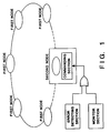
- Fig. 1 schematically shows the construction of this embodiment system.
- the second node includes an error detection section for detecting errors in the transmission path, a monitor section for observation with respect to time, and a commanding section which issues a system refreshment command described later if a certain error occurs in the transmission path or if passage of a certain period of time is detected by the monitor section.
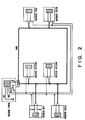
- Fig. 2 shows a more concrete example of the embodiment network system shown in Fig. 1. The present invention will be described below in detail with respect to the system shown in Fig. 2.
- Fig. 2 shows the overall connections of nodes used in the embodiment network system.
- the number of nodes used in this embodiment is limited to seven.
- the nodes are connected by a multiplex transmission path bus MB formed of twisted pair wires or the like.
- These multiplex nodes include a multiplex node CCS provided for a unit for display control of a navigation apparatus, an audio apparatus and so on, a multiplex node MT for meters, a multiplex node TEL for a mobile telephone adapter, a multiplex node ACU for an air conditioner control unit, a multiplex node ACSW for switches of the air control unit, a multiplex node STSW for switches provided around the steering wheel shaft, and a node TWS provided in a connection box for supplying power to each node and for connecting a self-diagnosis tester.
- TWS is an abbreviation of "total wiring system”.
- the switches provided around the steering wheel shaft include, for example, a turning-right switch, a turning-left switch, a small lamp switch, a horn switch, and a head lamp high beam switch.
- the meters include a turning-right indicator, a turning-left indicator and a head lamp high beam indicator.
- a door switch for detecting the open/closed state of a door is connected to the node TWS, as will be described below.
- a front multiplex node and a rear multiplex node may be further provided.
- the front multiplex node may have a front tuning-right signal lamp, a front turning-left signal lamp, front small lamps, a horn and so on
- the rear multiplex node may have a rear tuning-right signal lamp, a rear turning-left signal lamp, tail lamps and so on.
- the connection relationship between the nodes and the power supply is not limited to the relationship shown in Fig. 2, and may be selected as desired in consideration of operability, handling and so on.
- vehicle driving information is transmitted as a sequence of frames F each having a construction such as that shown in Fig. 3.
- the vehicle driving information includes a category of information that a switch is turned on for example.
- Each frame F is constructed to have an SD (start delimiter) code, a priority code, a frame ID code, data length, items of data 1 to N, and a check code.
- SD start delimiter
- SD code is a specific code for indicating the start of the frame F.
- the receiving multiplex node recognizes the start of the frame F when it receives the SD code.
- Primary code is a code for designating a priority order in which frame signals representing groups of data items simultaneously transmitted from a plurality of multiplex nodes and collision with each other are processed. If collision of a plurality of groups of data items takes place, one of the data groups having the highest priority is processed first. For example, "priority code” is used to determine one of the nodes from which a reply frame is received with priority, with respect to a later-mentioned system refreshment command issued from the TWS unit. This priority control will be explained later with reference to Fig. 13.
- “Frame ID code” is a code for identifying data assigned to bits in respective DATA fields. In other words, it is used to designate the node in which the present frame should be used, which operation corresponds to Functional Addressing described in the document “Proposal for a Vehicle Network Protocol Standard” made public in SAE International Congress and Exposition (February 1986).
- "Originator address” is a physical address of the node which transmits the present frame F. If physical addresses "1", “2”, “3”, “4", "5", “6”, and “7” are respectively assigned to the seven nodes CCS, MT, TEL, ACU, ACSW, STSW, and TWS of the system shown in Fig.
- a frame is sent to all the nodes if the corresponding ID is "0". For example, in a case where an "air control on” switch controlled by the node ACSW is turned on, and where it is necessary to light a display lamp “air control on” controlled by the node MT and to turn on the blower motor of the air conditioner controlled by the node ACU, it is necessary, for a frame containing information that the "air control on” switch has been turned on to be sent to the nodes MT, ACU and TWS.
- the ID of the frame for the case is "10" according to the above table. Needless to say, the contents of the above table are only examples and the above relationship can be set in any other way.
- a reception confirmation signal field (ACK field) shown in Fig. 3 will be described below.
- This field consists of a plurality of bits, e.g., 16 bits, and bits in advance determined for the respective multiplex nodes are provided in this field.
- Each node effects normal reception confirmation by using the corresponding bit of the ACK field. That is, the transmitting node sets only one of the bits of the ACK field at the position corresponding to itself to "0" while setting all the other bits to "1", i.e., setting one "0" bit and 15 “1” bits, and supplies these bits to the transmission path subsequently to the transmitted frame while setting a predetermined gap between the transmitted frame and the ACK field.
- Each of the receiving multiplex nodes checks whether or not there is any error in the content of the received frame by using the check code, and, if there is no error, returns to the originator node a reception confirmation signal (ACK signal) based on setting "0" in the corresponding one of the bit regions whose positions are in advance determined for the respective multiplex nodes. That is, it is recognized that the node which transmits ACK field in which the corresponding bit is "0" has received the frame normally.
- ACK signal reception confirmation signal
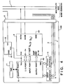
- Fig. 4 schematically shows the construction of a multiplex communication controller used in common for each of the nodes shown in Fig. 2.
- the multiplex communication controller 100 shown in Fig. 4 is connected to a main bus (MB) 1 corresponding to the transmission path MB shown in Fig. 2 through a connector 2.
- the controller 100 has a multiplex interface module 3, and a host CPU 8.
- the multiplex interface module 3 detects carrier/collision on the MB 1 and reads serial data from the MB 1 to convert into parallel data (D7 to D0).
- the interface module 3 sends the read 8 bit parallel data (D7 to D0) to the host CPU 8, and converts parallel data supplied from the CPU 8 into serial data.
- the interface module 3 also calculates the error detection code and effects other operations. That is, the interface module 3 effects a control at the physical level.
- the host CPU 8 switches actually used, loads (not shown) and so on are connected through wires 6 and 7, an input interface circuit 4 and an output interface circuit 5.
- the multiplex communication controller 100 also has a power supply circuit 10 which includes a DC-DC converter for producing Vcc from a 12 V battery voltage.
- the hardware of the multiplex communication LSI module 3 includes a controller (not shown) for effecting transmission control based on a PALNET system developed from the CSMA/CD system, a decoder/encoder (not shown) for effecting logical level signal conversion of data on the MB 1, a transceiver (not shown) directly connected to the MB 1 and serving as a level changer, and a DMA (not shown) for access to a memory of the CPU 8.
- Fig. 5 schematically shows a sequence of frame transmission/reception conducted between the nodes.
- the communication control at the physical level including frame sending control and error detection is effected by the multiplex communication LSI 3, while frame data processing, error re-transmission and so on are effected by the host CPU. Error processing and frame transmission/reception effected between the nodes will be described below with reference to Fig. 5.
- the multiplex communication LSI effects ACK replying, detects CRC errors, and informs the CPU 8 that an error has been detected.
- the kinds of error about which the CPU 8 is to be informed are "multiplex bus errors" and "node malfunction”.
- the following four kinds of error (ER's 1 to 4) are included in multiplex bus errors, and information on such errors is sent as status information from the multiplex communication LSI 3 to the CPU 8 through data lines D7 to D0 when the CPU 8 activates a status read terminal (SRC).
- This error is detected as an abnormal format on the transmission path.
- This error is detected as a passive state when the multiplex bus 1 is occupied.
- This error is detected as the "0" state of a bit TXRDY while a passive state continued for 0.1 ms or more is not found during a period of time of 6.2 ms.
- a node malfunction is such that the ACK is "1" (which indicates nonexistence) while the existence of the corresponding node is marked in "node registration data" controlled by the multiplex module.
- the CPU or the multiplex module of the corresponding node may be malfunctioning or a branch of the bus 1 is open.
- Information on such a node malfunction is sent as predetermined data (ACK data shown in Fig. 5) from the multiplex communication LSI module to the CPU 8.
- the host CPU 8 of the node ACSW which is informed through the input interface circuit 4 that the air conditioner switch has been turned on, prepares a frame, such as that shown in Fig. 3, which is to be transmitted to the multiplex communication controller of the ACU (air conditioner control unit).
- the host CPU 8 supplies this frame to the transmission path MB 1 through the multiplex interface module 3.
- the multiplex interface module 3' of the ACU multiplex communication controller receiving the frame data through the transmission path MB 1 analyzes the received frame data, and drives a compressor or the like of the air conditioner through the output interface circuit 5'.
- the algorithm of re-transmission in frame transmission is as described below.
- the number of re-transmission times is at most three. If one of the nodes returns the ACK at least one time during three times re-transmission, it is recognized that the frame has been normally transmitted to this node.
- 16 bits are provided in the ACK field in consideration of future extension, but there are at most seven active nodes as can be understood from Fig. 2. Accordingly, if there is no ACK bit in the ACK field, it is necessary, for the transmitting node to discriminate whether the ACK bit absence is due to an error or to the absence of the nodes.
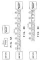
- Figs. 6A to 6C are diagrams relating to the interface between the host CPU 8 of a node and the multiplex communication LSI 3.
- Fig. 6A shows a format for transmission of status information from the LSI 3 to the CPU 8;
- Fig. 6B shows a format for transmission of data received by the LSI 3 to the CPU 8;
- Fig. 6C shows a format of data which is to be transmitted from the host CPU 8 to the LSI 3 when the frame is transmitted to other frames.
- Data ANC shown in Fig. 6B represents information on the ACK field received by the LSI 3.
- Data DID shown in Fig. 6C corresponds to the frame ID shown in Fig. 3.
- Data MP/ID corresponds to the priority code of Fig. 3. Conversion between the data formats shown in Figs. 6B and 6C and the frame format of Fig. 3 is effected by the LSI 3.
- the node TWS has the network control function and also has the functions of the ordinary nodes including that of observing door switches, as shown in Fig. 7.
- the operation of a door switch 20 for detecting the open/closed states of a door is observed by the node TWS (when the door is open, the switch is open), and a lamp 21 for warning that the door is open is controlled by the node MT.
- the switch 20 detects the open state of the door but a frame containing information on this state is not sent from the node TWS to the node MT owing to a communication problem (the above-mentioned error). In this state, the lamp 21 is not lighted although the switch 20 is open; the driver is not warned.
- the communication error is detected by the function F1, and "system refreshment" command is sent from the node TWS to all the nodes, or "system refreshment” command is automatically sent from the node TWS to all the nodes at intervals of 5 seconds by the function F2. Since the node TWS functions as the ordinary node, it sends a frame data indicating the opened state of the door switch to the node MT when informed of this "system refreshment" state. In this frame data, the bit corresponding to the switch 20 is "1". On the other hand, the MT node knows the bit construction of the frame data, i.e., the one-to-one correspondence between the bits and the switch status, and the CPU of the MT node lights the lamp 21 because the bit corresponding to the switch 20 is "1".
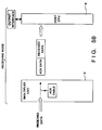
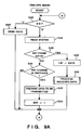
- Fig. 8 shows a control procedure for the LSI module of the node TWS
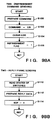
- Figs. 9A to 9D show a control procedure for the host CPU of the node TWS
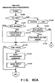
- Figs. 10A to 10C show a control procedure for the host CPU of the node MT.
- the reason for selecting the node TWS for the description of the control procedure is that the node TWS is the subject that supplies "system refreshment" command to the bus 1. All the nodes shown in Fig. 2 including the node TWS are to perform "system refreshment” operations by receiving the "system refreshment" command.
- the control procedure for the respective "system refreshment" operations of the nodes other than the node TWS as shown in Fig. 2 are the same.
- the control procedure for the "system refreshment" operation of the node other than the node TWS will be represented by the control procedure of the node MT.
- the node TWS has the function of observing the door switch.
- the node TWS is identical to each of the other ordinary nodes except that is controls the results of communication for the whole system. For this reason, the operation of the nodes TWS and MT will be described with reference to Figs. 8 to 10 for representation of the generation of "system refreshment" command and the "system refreshment" operation in this system.
- the control of the nodes TWS and MT shown in Figs. 8 to 10 will be first summarized below.
- the node TWS controls the results of communication for the whole system, and sends a frame having "system refreshment” command into the network according to the results. It also sends out "system refreshment” command at intervals of 5 seconds.
- the node TWS sends a "reply frame” into the network after producing "system refreshment” command, and the node MT also sends a "reply frame” into the network after receiving "system refreshment” command. That is, the node TWS sends the reply frame to the node MT. Also, the node MT delivers the reply frame to the other ordinary nodes or the node TWS.
- Each of the nodes TWS and MT corrects the states of its output device elements based on the received reply frame.
- step S18 examination is made as to whether or not data to be transmitted to the bus 1 has been received from the CPU 8. If no data is to be transmitted, the control proceeds to step S20 to wait for the presence of SD code from the nodes other than the node TWS on the bus MB. If SD code is detected, the corresponding frame is detected in step S22 (ACK bits are received in step S34). If at the time of this frame reception there is no error (CRC error, collision), status information indicating that there is no error while the data is supplied is prepared in step S26. In step S30, ACK is supplied to the MB 1 by the ACK timing of the node TWS (refer to Fig. 4).
- the LSI of the node TWS is set in the reception mode as well as in the transmission mode to receive ACK bits from the other nodes along with the ACK bit sent from itself.
- step S34 ACK bits from the other nodes are thereby received. Irrespective of whether or not the destination of the frame is the node TWS, the node TWS sends out the ACK bit (as in the case of the other nodes) provided that it receives the frame normally. The control then proceeds to step S35.
- step S24 If it is determined in step S24 that an error has been detected during frame reception, the control proceeds to step S31 to prepare status information that an error has occurred.
- step S32 the ACK timing for the node TWS is waited.
- step S34 the ACK bit is transmitted to the MB 1, and the control proceeds to step S35.
- the LSI has status information on the existence or non-existence of any error in communication, and information on the data and ACK used when there is no error.
- step S35 the frame reception is interrupted in the CPU 8 of the node TWS.
- step S36 the status data, the transmitted data and the ACK data are sent to the CPU 8 through the buses D7 to D0 (refer to Fig. 6).
- the control then proceeds to step S30. If the destination of the frame is not the node TWS, the control proceeds to step S38 for control of the ACK table controlled by the LSI of the node TWS (each node has the same ACK table).
- step S18 If it is determined in step S18 that there is frame data to be transmitted from the node TWS to some of the other nodes, the control proceeds to step S19 to send out this frame.
- the LSI is set in the reception mode to receive ACK bits from the other nodes while being set in the transmission mode to send the ACK bit for the node to which it belongs.
- the received ACK pattern is sent to the CPU 8 as in the case of frame reception. If collision with frames transmitted from some of the other nodes is detected at the time of frame transmission in step S19, the delay time till the re-transmission effected by this node is determined in consideration of the priority order. The determination of this delay time is based on the CSMA/CD method.
- a transmitted data flag SDF is used to examine whether or not the CPU of the node TWS has data which is to be transmitted to the LSI of this CPU. If transmitted data flag SDF is zero, the status of the TWS-LSI is examined in step S44, and examination is made in step S46 as to whether or not this LSI has frame data received from some of the other nodes. If there is no received data, the control proceeds to step S50 to examine whether or not there is any change in the states of the switches observed by the node TWS (including the door switch 20 shown in Fig. 7). If there is no change in the switches, the control returns to step S40.
- each ordinary node transmits no frame to the bus MB. If there is a change in the switches, data to be transmitted including data representing the states of the switches is prepared in step S52. In step S54, transmitted data flag SDF is set to "1".
- step S40 This setting of the flag to "1" is detected in step S40 and step S42 is then executed.
- step S42 data is sent from the CPU to the LSI. Details of this data sending are shown in Fig. 9B.
- step S46 If it is determined in step S46 that the LSI has received a frame, this data is read in step S60. This reading is as shown in Fig. 6B. In step S62, the received data is processed. Details of this data processing are shown in Fig. 9C.
- step S52 Data for informing the node MT of this change is prepared in step S52 (Fig. 9A). Then, a process of sending the data from the CPU of the node TWS to the LSI of the same node will be described below with reference to Fig. 9B.
- This control procedure includes sending of the data to the LSI and observation of whether or not the data has been correctly sent to the destination node.
- step S70 of the flow shown in Fig. 9B this data is sent to the LSI.
- the data format used at this time is as shown in Fig. 6C.
- step S72 based on LSI status information read in step S71, determination is made as to whether or not the frame transmission through the bus MB 1 has been completed.
- step S74 examination is made as to whether or not any multiplex bus error has occurred during the frame transmission. If an error has occurred, this error is counted and logged as an error in the node TWS in step S84 (refer to Fig. 11). That is, an error detected by the node TWS during the transmission from the same must be identified an error in the operation of the node TWS irrespective of the kind of cause. If no multiplex bus error has occurred, examination is made in step S76 as to whether or not there is an ACK error. If there are some ACK errors, the errors are counted in step S78 with respect to the nodes which have not returned the normal ACK (refer to Fig. ll). The nodes can be discriminated by examining the ACK bits.
- step S82 If neither multiplex bus error nor ACK error are found, the control proceeds to step S82 to reset transmitted data flag SDF. If at least one multiplex bus error or ACK error is found, the flag is not reset and the data which has not been successfully transmitted is sent to the LSI module to be transmitted to the network again.
- An error log such as that shown in Fig. 11 is used to count errors of each node with messages. That is, message numbers are attached to the data items in the frame, and the same message numbers are attached to re-transmitted messages. It is therefore possible for the CPU of the node TWS to discriminate whether the present data is data of received re-transmitted frame or data of a new frame.
- step S90 based on the log shown in Fig. 11, examination is made as to whether or not the limit of the number of re-transmission times is exceeded with respect to each of the nodes.
- the upper limit of the number of re-transmission times is set to three times.
- the ordinary frame is supplied to the bus MB to be transmitted from the node TWS to the node MT.
- Fig. 10A is a flow chart of a main control procedure for the host CPU of the node MT (the same procedure is used for the other nodes except for the node TWS).
- the control procedure for the LSI module of the node MT is substantially the same as that shown in Fig. 9B and therefore will not be described.
- the main routine of the CPU of the node MT shown in Fig. 10A is substantially the same as that of the node TWS (Fig. 9) except for details of data sending processing of step S172 (shown in Fig. 10C) and details of received data processing (shown in Fig. 10B). The description relating to Fig. 10A is omitted.
- step S220 examination is made as to whether or not the destination of the received frame is the node MT.
- step S222 data DID is examined to determine whether the received data is "system refreshment" command. In this situation the data is not "system refreshment” command, and the control proceeds to step S224 to examine a refreshment flag. This refreshment flag is presently zero since it is set in step S230 described later. The control therefore proceeds to step S226.
- step S226 the output device elements connected to the node MT are set according to the received data.
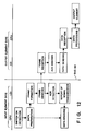
- Fig. 12 schematically shows data flow between nodes relating to operations other than "system refreshment" operations.
- Fig. 14 schematically shows the "system refreshment” operation.
- step S90 This time-over is detected in step S90 by the node TWS. If time-over has occurred with respect to at least one of the nodes, a "system refreshment command sending" subroutine is executed in step S92. Details of this subroutine are shown in Fig. 9BA.
- step S100 of the flow shown in Fig. 9BA data of "system refreshment” command is prepared.
- step S102 this data is sent to the LSI module of the node TWS.
- the format of "system refreshment” command is the one shown in Fig. 6C, in which DID (corresponding to the frame ID shown in Fig. 3) is zero.
- step S104 the log is cleared. This is because the status of the whole system is returned to the initial state by the "system refreshment" operation.
- step S106 a refreshment flag is set. This flag is used in step S134 described below.
- a subroutine for "reply frame sending" with respect to the "system refresment” command to the other nodes is executed in step S94.
- "Reply frame" of the node TWS is characterized as a response to the occurrence of a state necessitating "system refreshment” command rather than a reply to the "system refreshment” command. In this sense, it may be called “response frame” as shown in Fig. 14.
- step S110 the states of the input device elements connected to the node TWS are read.
- step S112 reply data for the node TWS itself is prepared.
- step S114 a sent data flag SDF is set. Then, in steps S40 to S42, sending of this reply data to the LSI is waited.
- the node TWS If the node TWS detects that the number of its errors exceeds the predetermined number or that number of ACK errors of some of the other nodes exceeds the the predetermined number, the node TWS sends "system refreshment" command in the form of a frame to all the nodes and also sends the states of its input device elements in the form of a reply frame to the node which needs to be informed of the states, e.g., the node MT.
- step S228 If YES in step S222 (Fig. 10B) on the node MT side, initialization of the CPU and the LSI of the node MT is effected in step S228.
- the refreshment flag is set in step S230, and the states of all the input device elements connected to the node MT are read in step S232.
- step S234 data for a reply frame sent in response to "system refreshment" command is prepared. This data includes priority data (MP/NID), the above read data and the function address of the destination node.
- sent data flag SDF is set.
- the signals of input device elements such as switches connected to some of the nodes may be sent to other nodes.
- the node MT may be provided with a plurality of switches from which signals must be sent to some of the other nodes, for example, the node CC and the node TWS.
- the function address must be set to "8" in accordance with the table shown above.
- the priority of the sent data is determined as described below. That is, higher priority is given to a reply frame sent from a node having a larger number of input device elements. This is because the states of the output device elements are determined by the signals from the input device elements. In a case where the states of elements, two input device elements I1 and I2 and two output device elements O1 and O2, are determined in the order of, for example, I1 ⁇ O1 ⁇ I2 ⁇ O2, the highest order must be given to the node to which the input device element I1 belongs.
- the process of reply frame reception control effected by the node TWS is shown as steps S132 to S142 in Fig. 9C.
- the corresponding process for the node MT is shown as step S224, steps S240 to S245 in Fig. 10B. These processes are the same and the process for the node MT will be described below.
- step S220 determination is made in step S220 as to whether or not the destination of this frame data is the node MT.
- the form of reply frames is the same as that of the ordinary frame. The control therefore proceeds from step S222 to step S224.
- step S240 examination is made as to whether there is any inconsistency between the data of the reply frame on the states of the input device elements of the destination node and the data on the states of the output device elements of the node MT. If an inconsistency is recognized, data on this inconsistency is logged.
- step S242 the state of the output device element exhibiting the inconsistency is set in accordance with the state of the input device element.
- step S244 examination is made as to whether or not such output device element setting has been effected with respect to all the output device elements of the node MT.
- step S224 If it is determined in step S224 that the setting has been effected with respect to all the elements, a refreshment flag is set in step S245.
- the output device elements of the corresponding nodes are corrected according to the states of the corresponding input device elements.
- system refreshment command is issued at times other than the time when the number of communication errors continuously taking place e>:ceeds the predetermined nurnber. That is, "system refreshment” command is sent from the node TWS to the bus 1 at intervals of 5 seconds, which command has the same format as the "system refreshment” command issued when the number of communication errors continuously taking place exceeds the predetermined number, and to which the same reply is returned from each node. Therefore the process of "system refreshment” command generation will be described below will be described below with reference to Fig. 9D alone.
- the flow chart shown in Fig. 9D represents an interrupt processing routine started by interrupt signals supplied from a timer chip 11 of the node TWS (shown in Fig. 4) at intervals of 5 seconds.
- the refreshment command sending subroutine details of which are shown in Fig. 9BA, is executed in step S160, and a reply frame sending subroutine is executed in step S162.
- step S164 a new period of time of 5 seconds is set in the timer chip 11. System refreshment is thereby effected every 5 seconds.
- the CSMA/CD type bus utilized as a part of the present invention, if collision between low and high levels supplied from two nodes takes place, only the low level is detected on the bus, as is well known.
- the node which sends the high level recognizes the occurrence of collision by detecting the low level.
- the priority code is placed next to SD bits, as shown in Fig. 3.
- a bit representing higher priority is disposed closer to SD bits. If data bits are examined successively starting from SD bits to recognize collision, the LSI module of the node which has sent a frame having the largest priority value must detect the collision first. In other words, a frame sent from the node of higher priority (having a smaller logical value) can be sent completely with a smaller possibility of errors.
- a re-start bit of the node having a priority "0011" is detected as zero, and the frame from this node is re-transmitted.
- the node which has detected the collision re-transmits its frame after a pre-determined time based on the well-known CSMA/CD algorism.
- the present invention can be modified in various ways without departing from its cope, as described below.
Landscapes
- Engineering & Computer Science (AREA)
- Computer Networks & Wireless Communication (AREA)
- Signal Processing (AREA)
- Environmental & Geological Engineering (AREA)
- Small-Scale Networks (AREA)
- Maintenance And Management Of Digital Transmission (AREA)
- Selective Calling Equipment (AREA)
Claims (17)
- Système de transmission multiplex à utiliser dans un véhicule, comprenant une pluralité de noeuds de transmission multiplex mutuellement reliés par un trajet de transmission multiplex commun comportant:une pluralité de premiers noeuds de transmission comportant une unité de commande de transmission pour commander la transmission entre lesdits noeuds fondée sur un protocole multiplex décentralisé, etun deuxième noeud de transmission comportant au moins une unité de commande de transmission pour commander la transmission à travers tout le système,
dans lequel ledit deuxième noeud de transmission comprend des moyens d'instruction pour instruire chacun de ladite pluralité des premiers noeuds de transmission pour fournir l'information sur l'état du noeud correspondant audit trajet de transmission,
caractériséen ce qu'un moyen de détection est prévu pour détecter les erreurs de transmission dans le système,en ce que ledit moyen d'instruction dudit deuxième noeud de transmission instruit chacun des premiers noeuds de transmission lorsque ledit moyen de détection détecte une erreur de transmission dans le système,en ce que chacun de ladite pluralité de premiers noeuds de transmission comprend des moyens pour recevoir et analyser l'information d'état des autres noeuds après réception de l'instruction dudit deuxième noeud de transmission et des moyens d'initialisation pour s'initialiser conformément aux résultats de l'analyse de l'information d'état. - Système selon la revendication 1, caractérisé en ce que ledit moyen de détection comporte des moyens pour observer le nombre de retransmissions des données retransmises fournies audit trajet de transmission multiplex, et reconnaît une erreur si le nombre de retransmissions dépasse un nombre prédéterminé.
- Système selon la revendication 1, caractérisé en ce que les premiers noeuds de transmission sont ceux destinés aux éléments de l'équipement électrique du véhicule, et en ce que l'information d'état comporte l'information sur l'état des éléments d'équipement électrique.
- Système selon la revendication 1, caractérisé en ce que lesdits premiers noeuds de transmission sont des noeuds de transmission pour les éléments d'équipement électrique du véhicule, et en ce que l'information d'état comporte l'information sur l'état des éléments d'équipement électrique.
- Système selon la revendication 4, caractérisé en ce que les éléments d'équipement électrique comportent un dispositif d'entrée tel qu'un commutateur ou un capteur, et en ce que l'information d'état comporte l'information sur l'état du dispositif d'entrée.
- Système selon la revendication 5, caractérisé en ce qu'une partie de ladite pluralité des premiers noeuds de transmission comprend:un noeud destiné aux éléments de l'équipement électrique comportant le dispositif d'entrée; etun autre noeud destiné aux équipements électriques comportant un dispositif de sortie tel qu'un actionneur correspondant au dispositif d'entrée.
- Système selon la revendication 6, caractérisé en ce que les moyens d'initialisation dudit noeud destiné aux équipements électriques comportant le dispositif de sortie initialisent le dispositif de sortie correspondant en correspondance avec l'information sur l'état du dispositif d'entrée contenue dans l'information d'état reçue.
- Système selon la revendication 1, caractérisé en ce que chacun de ladite pluralité de premiers noeuds comprend:un moyen pour transmettre l'information d'état sous la forme d'un bloc contenant l'information sur un ordre de priorité pour arbitrer une collision de données survenant sur ledit trajet de transmission;un moyen pour détecter la collision de données sur ledit trajet de transmission; etun moyen pour retransmettre le bloc contenant l'information d'état conformément à l'ordre de priorité lorsque la collision est détectée.
- Système selon la revendication 8, caractérisé en ce que si une partie de ladite pluralité de premiers noeuds de transmission comporte un noeud destiné aux éléments de l'équipement électrique comportant le dispositif d'entrée, et un autre noeud pour les équipements électriques comportant un dispositif de sortie tel qu'un actionneur correspondant au dispositif d'entrée, un ordre de priorité relativement élevé est donné au noeud destiné aux éléments électriques comportant l'élément du dispositif d'entrée.
- Système de transmission multiplex à utiliser dans un véhicule, comprenant une pluralité de noeuds de transmission multiplex mutuellement reliés par un trajet de transmission multiplex commun comportant:une pluralité de premiers noeuds de transmission comportant une unité de commande de transmission pour commander la transmission entre lesdits noeuds fondée sur un protocole multiplex décentralisé, etun deuxième noeud de transmission comportant au moins une unité de commande de transmission pour commander la transmission à travers tout le système,
dans lequel ledit deuxième noeud de transmission comprend des moyens d'instruction pour instruire chacun de ladite pluralité des premiers noeuds de transmission pour fournir l'information sur l'état du noeud correspondant audit trajet de transmission, caractériséen ce qu'un moyen d'observation est prévu pour observer l'écoulement d'une période de temps prédéterminée eten ce que le moyen d'instruction du deuxième noeud de transmission instruit chacun des premiers noeuds de transmission lorsque ledit moyen d'observation détecte l'écoulement d'une période de temps prédéterminée,en ce que ladite pluralité des premiers noeuds de transmission comprenddes moyens pour recevoir et analyser l'information d'état provenant des autres noeuds après réception de l'instruction provenant dudit deuxième noeud de transmission, et
des moyens pour s'initialiser selon les résultats de l'analyse de l'information d'état. - Système selon la revendication 10, caractérisé en ce que lesdits premiers noeuds de transmission sont ceux destinés aux éléments de l'équipement électrique du véhicule, et en ce que l'information d'état comporte l'information sur l'état des éléments de l'équipement électrique.
- Système selon la revendication 10, caractérisé en ce que lesdits premiers noeuds de transmission sont ceux destinés aux éléments de l'équipement électrique du véhicule, et en ce que l'information d'état présente l'information sur l'état des éléments de l'équipement électrique.
- Système selon la revendication 12, caractérisé en ce que les éléments de l'équipement électrique comportent un dispositif d'entrée tel qu'un commutateur ou un capteur, et en ce que l'information d'état comporte l'information sur l'état du dispositif d'entrée.
- Système selon la revendication 12, caractérisé en ce qu'une partie de ladite pluralité des premiers noeuds de transmission comprend:un noeud pour les éléments de l'équipement électrique comportant le dispositif d'entrée; etun autre noeud pour les équipements électriques comportant un dispositif de sortie tel qu'un actionneur correspondant au dispositif d'entrée.
- Système selon la revendication 14, caractérisé en ce que les moyens d'initialisation dudit noeud destiné aux équipements électriques comportant le dispositif de sortie initialisent le dispositif de sortie correspondant en correspondance avec l'information sur l'état du dispositif d'entrée contenue dans l'information d'état reçue.
- Système selon la revendication 10, caractérisé en ce que chacun de ladite pluralité de premiers noeuds comprend:un moyen pour envoyer l'information d'état sous la forme d'un bloc contenant l'information sur un ordre de priorité pour arbitrer une collision de données survenant sur ledit trajet de transmission;un moyen pour détecter la collision de données sur ledit trajet de transmission; etun moyen pour retransmettre le bloc contenant l'information d'état conformément à l'ordre de priorité lorsque la collision est détectée.
- Système selon la revendication 16, caractérisé en ce que si une partie de ladite pluralité des premiers noeuds de transmission comporte un noeud pour les éléments de l'équipement électrique comportant le dispositif d'entrée, et un autre noeud pour les équipements électriques comportant un dispositif de sortie tel qu'un actionneur correspondant au dispositif d'entrée, un ordre de priorité relativement élevé est donné au noeud destiné aux éléments électriques comportant l'élément du dispositif d'entrée.
Applications Claiming Priority (2)
| Application Number | Priority Date | Filing Date | Title |
|---|---|---|---|
| JP126714/89 | 1989-05-22 | ||
| JP1126714A JP2904283B2 (ja) | 1989-05-22 | 1989-05-22 | 車両用多重伝送装置 |
Publications (3)
| Publication Number | Publication Date |
|---|---|
| EP0399491A2 EP0399491A2 (fr) | 1990-11-28 |
| EP0399491A3 EP0399491A3 (fr) | 1993-05-12 |
| EP0399491B1 true EP0399491B1 (fr) | 1996-01-31 |
Family
ID=14942047
Family Applications (1)
| Application Number | Title | Priority Date | Filing Date |
|---|---|---|---|
| EP90109766A Expired - Lifetime EP0399491B1 (fr) | 1989-05-22 | 1990-05-22 | Système de transmission multiplex pour utilisation dans un véhicule |
Country Status (4)
| Country | Link |
|---|---|
| US (1) | US5090012A (fr) |
| EP (1) | EP0399491B1 (fr) |
| JP (1) | JP2904283B2 (fr) |
| DE (1) | DE69025094T2 (fr) |
Families Citing this family (146)
| Publication number | Priority date | Publication date | Assignee | Title |
|---|---|---|---|---|
| JP2904297B2 (ja) * | 1990-03-30 | 1999-06-14 | マツダ株式会社 | 車両用多重伝送装置 |
| JP2904298B2 (ja) * | 1990-03-30 | 1999-06-14 | マツダ株式会社 | 車両用多重伝送装置 |
| JP2904296B2 (ja) * | 1990-03-30 | 1999-06-14 | マツダ株式会社 | 車両用多重伝送装置 |
| DE69125772T2 (de) * | 1990-09-13 | 1997-07-31 | Mazda Motor | Multiplexübertragungssystem für Fahrzeuge |
| JP2873514B2 (ja) * | 1991-03-27 | 1999-03-24 | マツダ株式会社 | 多重伝送方法 |
| DE4129205A1 (de) * | 1991-03-28 | 1992-10-01 | Bosch Gmbh Robert | Verfahren zum aufbau von botschaften fuer den datenaustausch und/oder fuer die synchronisation von prozessen in datenverarbeitungsanlagen |
| US5357525A (en) * | 1991-04-02 | 1994-10-18 | The Furukawa Electric Co., Ltd. | Multiplex transmission system |
| US5307340A (en) * | 1991-04-02 | 1994-04-26 | The Furukawa Electric Co., Ltd. | Multipath transmission system with a troubleshooting arrangement for detecting failure |
| US5379292A (en) * | 1991-07-08 | 1995-01-03 | Naldec Corporation | Apparatus having priority order storages for recovery from failure of multiplex data transmission |
| KR0124373B1 (ko) * | 1991-08-30 | 1997-12-01 | 와다 요시히로 | 차량용 다중전송장치 |
| DE4238488A1 (fr) * | 1991-11-18 | 1993-06-17 | Furukawa Electric Co Ltd | |
| JP3051533B2 (ja) * | 1991-12-26 | 2000-06-12 | マツダ株式会社 | 多重伝送方法及び多重伝送装置 |
| JPH05276561A (ja) * | 1992-03-30 | 1993-10-22 | Mazda Motor Corp | 多重通信装置 |
| JPH06112962A (ja) * | 1992-09-30 | 1994-04-22 | Naldec Kk | 多重伝送方式 |
| JP2844036B2 (ja) * | 1992-10-20 | 1999-01-06 | 三菱電機株式会社 | 通信制御装置 |
| JPH06169313A (ja) * | 1992-11-30 | 1994-06-14 | Mazda Motor Corp | 多重伝送装置 |
| US5749070A (en) * | 1993-09-09 | 1998-05-05 | Apple Computer, Inc. | Multi-representational data structure for recognition in computer systems |
| US5701418A (en) * | 1994-03-31 | 1997-12-23 | Chrysler Corporation | Intra-vehicular LAN and method of routing messages along it using hash functions |
| EP0812049A4 (fr) * | 1995-02-21 | 2000-06-07 | Hitachi Ltd | Appareil et procede de fourniture d'electricite a un vehicule, dispositif a circuits semiconducteurs a utiliser dans ledit appareil et dispositif de cablage commun pour une automobile ou un autre vehicule |
| US5651009A (en) * | 1995-05-02 | 1997-07-22 | Motorola, Inc. | System and method for hybrid contention/polling protocol collision resolution using a depth first search technique |
| DE19530727B4 (de) * | 1995-08-18 | 2012-09-20 | Kiekert Ag | Verfahren zum Betrieb eines Steuersystems zur Steuerung von Kraftfahrzeugkomponenten |
| JP3438473B2 (ja) * | 1996-06-20 | 2003-08-18 | 矢崎総業株式会社 | 多重伝送システム、およびこれに用いられる異常処理制御方法並びに異常処理装置 |
| DE19754640A1 (de) * | 1997-12-09 | 1999-06-10 | Bosch Gmbh Robert | Verfahren zur Koordination von Netzwerkkomponenten |
| US8645137B2 (en) | 2000-03-16 | 2014-02-04 | Apple Inc. | Fast, language-independent method for user authentication by voice |
| DE10111286B4 (de) * | 2001-03-09 | 2005-04-21 | Audi Ag | Steuerungssystem und Verfahren zur Steuerung von Kraftfahrzeugkomponenten |
| JP4037129B2 (ja) * | 2002-02-27 | 2008-01-23 | カルソニックカンセイ株式会社 | 多重通信装置及びそれを用いた乗員保護装置 |
| US20050005167A1 (en) * | 2003-07-02 | 2005-01-06 | Kelly Thomas J. | Systems and methods for providing security operations in a work machine |
| US7983820B2 (en) * | 2003-07-02 | 2011-07-19 | Caterpillar Inc. | Systems and methods for providing proxy control functions in a work machine |
| US7516244B2 (en) | 2003-07-02 | 2009-04-07 | Caterpillar Inc. | Systems and methods for providing server operations in a work machine |
| US20050002354A1 (en) * | 2003-07-02 | 2005-01-06 | Kelly Thomas J. | Systems and methods for providing network communications between work machines |
| US7532640B2 (en) | 2003-07-02 | 2009-05-12 | Caterpillar Inc. | Systems and methods for performing protocol conversions in a machine |
| US8677377B2 (en) | 2005-09-08 | 2014-03-18 | Apple Inc. | Method and apparatus for building an intelligent automated assistant |
| DE102006009658A1 (de) * | 2006-03-02 | 2007-09-06 | Robert Bosch Gmbh | Steuervorrichtung |
| DE102006013872A1 (de) | 2006-03-23 | 2007-09-27 | Robert Bosch Gmbh | Verfahren und System zum Übertragen von Daten |
| US9318108B2 (en) | 2010-01-18 | 2016-04-19 | Apple Inc. | Intelligent automated assistant |
| DE102007015122A1 (de) * | 2007-03-29 | 2008-10-02 | Bayerische Motoren Werke Aktiengesellschaft | Verfahren zum Transfer von Daten in mehrere Steuergeräte |
| US8977255B2 (en) | 2007-04-03 | 2015-03-10 | Apple Inc. | Method and system for operating a multi-function portable electronic device using voice-activation |
| US9330720B2 (en) | 2008-01-03 | 2016-05-03 | Apple Inc. | Methods and apparatus for altering audio output signals |
| US8996376B2 (en) | 2008-04-05 | 2015-03-31 | Apple Inc. | Intelligent text-to-speech conversion |
| US10496753B2 (en) | 2010-01-18 | 2019-12-03 | Apple Inc. | Automatically adapting user interfaces for hands-free interaction |
| US20100030549A1 (en) | 2008-07-31 | 2010-02-04 | Lee Michael M | Mobile device having human language translation capability with positional feedback |
| WO2010067118A1 (fr) | 2008-12-11 | 2010-06-17 | Novauris Technologies Limited | Reconnaissance de la parole associée à un dispositif mobile |
| EP2359534B1 (fr) * | 2008-12-15 | 2014-05-07 | Hewlett-Packard Development Company, L.P. | Détection d'une liaison non fiable dans un système informatique |
| US10241752B2 (en) | 2011-09-30 | 2019-03-26 | Apple Inc. | Interface for a virtual digital assistant |
| US10241644B2 (en) | 2011-06-03 | 2019-03-26 | Apple Inc. | Actionable reminder entries |
| US9858925B2 (en) | 2009-06-05 | 2018-01-02 | Apple Inc. | Using context information to facilitate processing of commands in a virtual assistant |
| US10706373B2 (en) | 2011-06-03 | 2020-07-07 | Apple Inc. | Performing actions associated with task items that represent tasks to perform |
| US9431006B2 (en) | 2009-07-02 | 2016-08-30 | Apple Inc. | Methods and apparatuses for automatic speech recognition |
| US9007181B2 (en) * | 2010-01-08 | 2015-04-14 | Tyco Fire & Security Gmbh | Method and system for discovery and transparent status reporting for sensor networks |
| US10705794B2 (en) | 2010-01-18 | 2020-07-07 | Apple Inc. | Automatically adapting user interfaces for hands-free interaction |
| US10276170B2 (en) | 2010-01-18 | 2019-04-30 | Apple Inc. | Intelligent automated assistant |
| US10553209B2 (en) | 2010-01-18 | 2020-02-04 | Apple Inc. | Systems and methods for hands-free notification summaries |
| US10679605B2 (en) | 2010-01-18 | 2020-06-09 | Apple Inc. | Hands-free list-reading by intelligent automated assistant |
| US8682667B2 (en) | 2010-02-25 | 2014-03-25 | Apple Inc. | User profiling for selecting user specific voice input processing information |
| US10762293B2 (en) | 2010-12-22 | 2020-09-01 | Apple Inc. | Using parts-of-speech tagging and named entity recognition for spelling correction |
| US9262612B2 (en) | 2011-03-21 | 2016-02-16 | Apple Inc. | Device access using voice authentication |
| US10057736B2 (en) | 2011-06-03 | 2018-08-21 | Apple Inc. | Active transport based notifications |
| US8994660B2 (en) | 2011-08-29 | 2015-03-31 | Apple Inc. | Text correction processing |
| US10134385B2 (en) | 2012-03-02 | 2018-11-20 | Apple Inc. | Systems and methods for name pronunciation |
| US9483461B2 (en) | 2012-03-06 | 2016-11-01 | Apple Inc. | Handling speech synthesis of content for multiple languages |
| US9280610B2 (en) | 2012-05-14 | 2016-03-08 | Apple Inc. | Crowd sourcing information to fulfill user requests |
| US9721563B2 (en) | 2012-06-08 | 2017-08-01 | Apple Inc. | Name recognition system |
| US9495129B2 (en) | 2012-06-29 | 2016-11-15 | Apple Inc. | Device, method, and user interface for voice-activated navigation and browsing of a document |
| US9576574B2 (en) | 2012-09-10 | 2017-02-21 | Apple Inc. | Context-sensitive handling of interruptions by intelligent digital assistant |
| US9547647B2 (en) | 2012-09-19 | 2017-01-17 | Apple Inc. | Voice-based media searching |
| EP4560630A3 (fr) | 2013-02-07 | 2025-08-06 | Apple Inc. | Déclencheur vocal pour assistant numérique |
| US9368114B2 (en) | 2013-03-14 | 2016-06-14 | Apple Inc. | Context-sensitive handling of interruptions |
| CN105027197B (zh) | 2013-03-15 | 2018-12-14 | 苹果公司 | 训练至少部分语音命令系统 |
| WO2014144579A1 (fr) | 2013-03-15 | 2014-09-18 | Apple Inc. | Système et procédé pour mettre à jour un modèle de reconnaissance de parole adaptatif |
| WO2014197334A2 (fr) | 2013-06-07 | 2014-12-11 | Apple Inc. | Système et procédé destinés à une prononciation de mots spécifiée par l'utilisateur dans la synthèse et la reconnaissance de la parole |
| WO2014197336A1 (fr) | 2013-06-07 | 2014-12-11 | Apple Inc. | Système et procédé pour détecter des erreurs dans des interactions avec un assistant numérique utilisant la voix |
| US9582608B2 (en) | 2013-06-07 | 2017-02-28 | Apple Inc. | Unified ranking with entropy-weighted information for phrase-based semantic auto-completion |
| WO2014197335A1 (fr) | 2013-06-08 | 2014-12-11 | Apple Inc. | Interprétation et action sur des commandes qui impliquent un partage d'informations avec des dispositifs distants |
| EP3008641A1 (fr) | 2013-06-09 | 2016-04-20 | Apple Inc. | Dispositif, procédé et interface utilisateur graphique permettant la persistance d'une conversation dans un minimum de deux instances d'un assistant numérique |
| US10176167B2 (en) | 2013-06-09 | 2019-01-08 | Apple Inc. | System and method for inferring user intent from speech inputs |
| HK1220313A1 (zh) | 2013-06-13 | 2017-04-28 | 苹果公司 | 用於由语音命令发起的紧急呼叫的系统和方法 |
| US10791216B2 (en) | 2013-08-06 | 2020-09-29 | Apple Inc. | Auto-activating smart responses based on activities from remote devices |
| US9620105B2 (en) | 2014-05-15 | 2017-04-11 | Apple Inc. | Analyzing audio input for efficient speech and music recognition |
| US10592095B2 (en) | 2014-05-23 | 2020-03-17 | Apple Inc. | Instantaneous speaking of content on touch devices |
| US9502031B2 (en) | 2014-05-27 | 2016-11-22 | Apple Inc. | Method for supporting dynamic grammars in WFST-based ASR |
| US9785630B2 (en) | 2014-05-30 | 2017-10-10 | Apple Inc. | Text prediction using combined word N-gram and unigram language models |
| US9633004B2 (en) | 2014-05-30 | 2017-04-25 | Apple Inc. | Better resolution when referencing to concepts |
| US9734193B2 (en) | 2014-05-30 | 2017-08-15 | Apple Inc. | Determining domain salience ranking from ambiguous words in natural speech |
| US9966065B2 (en) | 2014-05-30 | 2018-05-08 | Apple Inc. | Multi-command single utterance input method |
| US9715875B2 (en) | 2014-05-30 | 2017-07-25 | Apple Inc. | Reducing the need for manual start/end-pointing and trigger phrases |
| US9842101B2 (en) | 2014-05-30 | 2017-12-12 | Apple Inc. | Predictive conversion of language input |
| US9760559B2 (en) | 2014-05-30 | 2017-09-12 | Apple Inc. | Predictive text input |
| US10078631B2 (en) | 2014-05-30 | 2018-09-18 | Apple Inc. | Entropy-guided text prediction using combined word and character n-gram language models |
| US10289433B2 (en) | 2014-05-30 | 2019-05-14 | Apple Inc. | Domain specific language for encoding assistant dialog |
| US10170123B2 (en) | 2014-05-30 | 2019-01-01 | Apple Inc. | Intelligent assistant for home automation |
| US9430463B2 (en) | 2014-05-30 | 2016-08-30 | Apple Inc. | Exemplar-based natural language processing |
| US9338493B2 (en) | 2014-06-30 | 2016-05-10 | Apple Inc. | Intelligent automated assistant for TV user interactions |
| US10659851B2 (en) | 2014-06-30 | 2020-05-19 | Apple Inc. | Real-time digital assistant knowledge updates |
| US10446141B2 (en) | 2014-08-28 | 2019-10-15 | Apple Inc. | Automatic speech recognition based on user feedback |
| US9818400B2 (en) | 2014-09-11 | 2017-11-14 | Apple Inc. | Method and apparatus for discovering trending terms in speech requests |
| US10789041B2 (en) | 2014-09-12 | 2020-09-29 | Apple Inc. | Dynamic thresholds for always listening speech trigger |
| US9606986B2 (en) | 2014-09-29 | 2017-03-28 | Apple Inc. | Integrated word N-gram and class M-gram language models |
| US9886432B2 (en) | 2014-09-30 | 2018-02-06 | Apple Inc. | Parsimonious handling of word inflection via categorical stem + suffix N-gram language models |
| US9646609B2 (en) | 2014-09-30 | 2017-05-09 | Apple Inc. | Caching apparatus for serving phonetic pronunciations |
| US10074360B2 (en) | 2014-09-30 | 2018-09-11 | Apple Inc. | Providing an indication of the suitability of speech recognition |
| US9668121B2 (en) | 2014-09-30 | 2017-05-30 | Apple Inc. | Social reminders |
| US10127911B2 (en) | 2014-09-30 | 2018-11-13 | Apple Inc. | Speaker identification and unsupervised speaker adaptation techniques |
| US10552013B2 (en) | 2014-12-02 | 2020-02-04 | Apple Inc. | Data detection |
| US9711141B2 (en) | 2014-12-09 | 2017-07-18 | Apple Inc. | Disambiguating heteronyms in speech synthesis |
| US9865280B2 (en) | 2015-03-06 | 2018-01-09 | Apple Inc. | Structured dictation using intelligent automated assistants |
| US9886953B2 (en) | 2015-03-08 | 2018-02-06 | Apple Inc. | Virtual assistant activation |
| US10567477B2 (en) | 2015-03-08 | 2020-02-18 | Apple Inc. | Virtual assistant continuity |
| US9721566B2 (en) | 2015-03-08 | 2017-08-01 | Apple Inc. | Competing devices responding to voice triggers |
| US9899019B2 (en) | 2015-03-18 | 2018-02-20 | Apple Inc. | Systems and methods for structured stem and suffix language models |
| US9842105B2 (en) | 2015-04-16 | 2017-12-12 | Apple Inc. | Parsimonious continuous-space phrase representations for natural language processing |
| US10083688B2 (en) | 2015-05-27 | 2018-09-25 | Apple Inc. | Device voice control for selecting a displayed affordance |
| US10127220B2 (en) | 2015-06-04 | 2018-11-13 | Apple Inc. | Language identification from short strings |
| US10101822B2 (en) | 2015-06-05 | 2018-10-16 | Apple Inc. | Language input correction |
| US10186254B2 (en) | 2015-06-07 | 2019-01-22 | Apple Inc. | Context-based endpoint detection |
| US11025565B2 (en) | 2015-06-07 | 2021-06-01 | Apple Inc. | Personalized prediction of responses for instant messaging |
| US10255907B2 (en) | 2015-06-07 | 2019-04-09 | Apple Inc. | Automatic accent detection using acoustic models |
| US10747498B2 (en) | 2015-09-08 | 2020-08-18 | Apple Inc. | Zero latency digital assistant |
| US10671428B2 (en) | 2015-09-08 | 2020-06-02 | Apple Inc. | Distributed personal assistant |
| US9697820B2 (en) | 2015-09-24 | 2017-07-04 | Apple Inc. | Unit-selection text-to-speech synthesis using concatenation-sensitive neural networks |
| US10366158B2 (en) | 2015-09-29 | 2019-07-30 | Apple Inc. | Efficient word encoding for recurrent neural network language models |
| US11010550B2 (en) | 2015-09-29 | 2021-05-18 | Apple Inc. | Unified language modeling framework for word prediction, auto-completion and auto-correction |
| US11587559B2 (en) | 2015-09-30 | 2023-02-21 | Apple Inc. | Intelligent device identification |
| US10691473B2 (en) | 2015-11-06 | 2020-06-23 | Apple Inc. | Intelligent automated assistant in a messaging environment |
| US10049668B2 (en) | 2015-12-02 | 2018-08-14 | Apple Inc. | Applying neural network language models to weighted finite state transducers for automatic speech recognition |
| US10223066B2 (en) | 2015-12-23 | 2019-03-05 | Apple Inc. | Proactive assistance based on dialog communication between devices |
| US10446143B2 (en) | 2016-03-14 | 2019-10-15 | Apple Inc. | Identification of voice inputs providing credentials |
| US9934775B2 (en) | 2016-05-26 | 2018-04-03 | Apple Inc. | Unit-selection text-to-speech synthesis based on predicted concatenation parameters |
| US9972304B2 (en) | 2016-06-03 | 2018-05-15 | Apple Inc. | Privacy preserving distributed evaluation framework for embedded personalized systems |
| US10249300B2 (en) | 2016-06-06 | 2019-04-02 | Apple Inc. | Intelligent list reading |
| US10049663B2 (en) | 2016-06-08 | 2018-08-14 | Apple, Inc. | Intelligent automated assistant for media exploration |
| DK179588B1 (en) | 2016-06-09 | 2019-02-22 | Apple Inc. | INTELLIGENT AUTOMATED ASSISTANT IN A HOME ENVIRONMENT |
| US10586535B2 (en) | 2016-06-10 | 2020-03-10 | Apple Inc. | Intelligent digital assistant in a multi-tasking environment |
| US10509862B2 (en) | 2016-06-10 | 2019-12-17 | Apple Inc. | Dynamic phrase expansion of language input |
| US10490187B2 (en) | 2016-06-10 | 2019-11-26 | Apple Inc. | Digital assistant providing automated status report |
| US10067938B2 (en) | 2016-06-10 | 2018-09-04 | Apple Inc. | Multilingual word prediction |
| US10192552B2 (en) | 2016-06-10 | 2019-01-29 | Apple Inc. | Digital assistant providing whispered speech |
| DK201670540A1 (en) | 2016-06-11 | 2018-01-08 | Apple Inc | Application integration with a digital assistant |
| DK179049B1 (en) | 2016-06-11 | 2017-09-18 | Apple Inc | Data driven natural language event detection and classification |
| DK179415B1 (en) | 2016-06-11 | 2018-06-14 | Apple Inc | Intelligent device arbitration and control |
| DK179343B1 (en) | 2016-06-11 | 2018-05-14 | Apple Inc | Intelligent task discovery |
| US10593346B2 (en) | 2016-12-22 | 2020-03-17 | Apple Inc. | Rank-reduced token representation for automatic speech recognition |
| DK179745B1 (en) | 2017-05-12 | 2019-05-01 | Apple Inc. | SYNCHRONIZATION AND TASK DELEGATION OF A DIGITAL ASSISTANT |
| DK201770431A1 (en) | 2017-05-15 | 2018-12-20 | Apple Inc. | Optimizing dialogue policy decisions for digital assistants using implicit feedback |
| US12229058B2 (en) | 2018-12-17 | 2025-02-18 | Graco Minnesota Inc. | Large packet daisy chain serial bus |
| JP2022514545A (ja) * | 2018-12-17 | 2022-02-14 | グラコ ミネソタ インコーポレーテッド | 大容量デイジーチェーンシリアルバス |
| JP7354600B2 (ja) * | 2019-06-10 | 2023-10-03 | マツダ株式会社 | 車載ネットワークシステム |
Family Cites Families (4)
| Publication number | Priority date | Publication date | Assignee | Title |
|---|---|---|---|---|
| JPS58134554A (ja) * | 1982-02-03 | 1983-08-10 | Nec Corp | 伝送路監視装置 |
| JPS624658A (ja) * | 1985-07-01 | 1987-01-10 | Sumitomo Electric Ind Ltd | 多重通信システム |
| JPH0771088B2 (ja) * | 1987-04-06 | 1995-07-31 | 古河電気工業株式会社 | 多重伝送方式 |
| SE458886B (sv) * | 1987-09-04 | 1989-05-16 | Ericsson Telefon Ab L M | Foerfarande och system foer att oeverfoera information och styra komponenter |
-
1989
- 1989-05-22 JP JP1126714A patent/JP2904283B2/ja not_active Expired - Fee Related
-
1990
- 1990-05-21 US US07/525,840 patent/US5090012A/en not_active Expired - Lifetime
- 1990-05-22 DE DE69025094T patent/DE69025094T2/de not_active Expired - Fee Related
- 1990-05-22 EP EP90109766A patent/EP0399491B1/fr not_active Expired - Lifetime
Also Published As
| Publication number | Publication date |
|---|---|
| DE69025094T2 (de) | 1996-06-13 |
| JP2904283B2 (ja) | 1999-06-14 |
| EP0399491A2 (fr) | 1990-11-28 |
| US5090012A (en) | 1992-02-18 |
| DE69025094D1 (de) | 1996-03-14 |
| EP0399491A3 (fr) | 1993-05-12 |
| JPH02306743A (ja) | 1990-12-20 |
Similar Documents
| Publication | Publication Date | Title |
|---|---|---|
| US5090012A (en) | Multiplex transmission system for use in a vehicle | |
| EP0367177B1 (fr) | Système de transmission par multiplex pour véhicules automobiles | |
| EP0319271B1 (fr) | Système de transmission en multiplex | |
| EP0319270B1 (fr) | Système de transmission en multiplex | |
| EP1839150B1 (fr) | Systeme d'enregistrement de donnees relatives au diagnostic de pannes | |
| EP0449304B1 (fr) | Système de transmission multiplexé pour être utilisé dans des véhicules | |
| US10560282B2 (en) | Control area network (CAN) transceivers with automatic polarity detection | |
| KR102304852B1 (ko) | 차량 제어기 고장 진단 또는 동작 감시 방법 및 장치 | |
| EP0862296A2 (fr) | Système de communication de données et unité de contrÔle électronique utilisée dans celui-ci | |
| KR100362236B1 (ko) | 다중데이타통신시스템 | |
| JP7415364B2 (ja) | 車載中継装置、コンピュータプログラム及び故障判定方法 | |
| MXPA03008466A (es) | Dispositivo para diagnosticos lejanos (rdu). | |
| JP2005145262A (ja) | 車載用lanシステム | |
| JP2925546B2 (ja) | 車両用断芯検出装置 | |
| JP2849402B2 (ja) | 車両用故障診断装置 | |
| JP3383462B2 (ja) | 多重伝送システム | |
| JP3088200B2 (ja) | 多重通信装置 | |
| JP3401361B2 (ja) | 多重伝送システム | |
| JPH01143533A (ja) | 多重伝送方法 | |
| JPH08275269A (ja) | 多重伝送システム | |
| JPH01143535A (ja) | 多重伝送方式 | |
| JPH04160939A (ja) | 車両用多重伝送装置 | |
| JPH04160938A (ja) | 車両用多重伝送装置 | |
| Lupini et al. | Class 2: General Motors' version of SAE J1850 | |
| JPH02121495A (ja) | 車両用多重伝送装置 |
Legal Events
| Date | Code | Title | Description |
|---|---|---|---|
| PUAI | Public reference made under article 153(3) epc to a published international application that has entered the european phase |
Free format text: ORIGINAL CODE: 0009012 |
|
| AK | Designated contracting states |
Kind code of ref document: A2 Designated state(s): DE FR GB |
|
| PUAL | Search report despatched |
Free format text: ORIGINAL CODE: 0009013 |
|
| AK | Designated contracting states |
Kind code of ref document: A3 Designated state(s): DE FR GB |
|
| 17P | Request for examination filed |
Effective date: 19930913 |
|
| 17Q | First examination report despatched |
Effective date: 19940914 |
|
| GRAA | (expected) grant |
Free format text: ORIGINAL CODE: 0009210 |
|
| AK | Designated contracting states |
Kind code of ref document: B1 Designated state(s): DE FR GB |
|
| REF | Corresponds to: |
Ref document number: 69025094 Country of ref document: DE Date of ref document: 19960314 |
|
| ET | Fr: translation filed | ||
| PLBE | No opposition filed within time limit |
Free format text: ORIGINAL CODE: 0009261 |
|
| STAA | Information on the status of an ep patent application or granted ep patent |
Free format text: STATUS: NO OPPOSITION FILED WITHIN TIME LIMIT |
|
| 26N | No opposition filed | ||
| PGFP | Annual fee paid to national office [announced via postgrant information from national office to epo] |
Ref country code: GB Payment date: 19970513 Year of fee payment: 8 Ref country code: FR Payment date: 19970513 Year of fee payment: 8 |
|
| PG25 | Lapsed in a contracting state [announced via postgrant information from national office to epo] |
Ref country code: GB Free format text: LAPSE BECAUSE OF NON-PAYMENT OF DUE FEES Effective date: 19980522 |
|
| PG25 | Lapsed in a contracting state [announced via postgrant information from national office to epo] |
Ref country code: FR Free format text: LAPSE BECAUSE OF NON-PAYMENT OF DUE FEES Effective date: 19980531 |
|
| GBPC | Gb: european patent ceased through non-payment of renewal fee |
Effective date: 19980522 |
|
| REG | Reference to a national code |
Ref country code: FR Ref legal event code: ST |
|
| PGFP | Annual fee paid to national office [announced via postgrant information from national office to epo] |
Ref country code: DE Payment date: 20010514 Year of fee payment: 12 |
|
| PG25 | Lapsed in a contracting state [announced via postgrant information from national office to epo] |
Ref country code: DE Free format text: LAPSE BECAUSE OF NON-PAYMENT OF DUE FEES Effective date: 20021203 |