EP0401026B1 - Bildübertragungsvorrichtung - Google Patents
Bildübertragungsvorrichtung Download PDFInfo
- Publication number
- EP0401026B1 EP0401026B1 EP90305959A EP90305959A EP0401026B1 EP 0401026 B1 EP0401026 B1 EP 0401026B1 EP 90305959 A EP90305959 A EP 90305959A EP 90305959 A EP90305959 A EP 90305959A EP 0401026 B1 EP0401026 B1 EP 0401026B1
- Authority
- EP
- European Patent Office
- Prior art keywords
- recording
- ink
- recovery
- control means
- signal
- Prior art date
- Legal status (The legal status is an assumption and is not a legal conclusion. Google has not performed a legal analysis and makes no representation as to the accuracy of the status listed.)
- Expired - Lifetime
Links
- 238000004891 communication Methods 0.000 title claims description 23
- 238000011084 recovery Methods 0.000 claims description 32
- 230000005540 biological transmission Effects 0.000 claims description 26
- 238000000034 method Methods 0.000 claims description 18
- 238000004321 preservation Methods 0.000 description 13
- 238000001704 evaporation Methods 0.000 description 4
- 230000008020 evaporation Effects 0.000 description 4
- 239000007788 liquid Substances 0.000 description 3
- 230000004044 response Effects 0.000 description 3
- 238000010586 diagram Methods 0.000 description 2
- 238000001444 catalytic combustion detection Methods 0.000 description 1
- 238000006243 chemical reaction Methods 0.000 description 1
- 238000001035 drying Methods 0.000 description 1
- 239000000428 dust Substances 0.000 description 1
- 230000037452 priming Effects 0.000 description 1
- 238000010926 purge Methods 0.000 description 1
- 238000004904 shortening Methods 0.000 description 1
Images


Classifications
-
- B—PERFORMING OPERATIONS; TRANSPORTING
- B41—PRINTING; LINING MACHINES; TYPEWRITERS; STAMPS
- B41J—TYPEWRITERS; SELECTIVE PRINTING MECHANISMS, i.e. MECHANISMS PRINTING OTHERWISE THAN FROM A FORME; CORRECTION OF TYPOGRAPHICAL ERRORS
- B41J2/00—Typewriters or selective printing mechanisms characterised by the printing or marking process for which they are designed
- B41J2/005—Typewriters or selective printing mechanisms characterised by the printing or marking process for which they are designed characterised by bringing liquid or particles selectively into contact with a printing material
- B41J2/01—Ink jet
- B41J2/135—Nozzles
- B41J2/165—Prevention or detection of nozzle clogging, e.g. cleaning, capping or moistening for nozzles
- B41J2/16585—Prevention or detection of nozzle clogging, e.g. cleaning, capping or moistening for nozzles for paper-width or non-reciprocating print heads
Definitions
- the present invention relates to an image communication apparatus for ejecting a liquid droplet onto a recording member to perform image recording.
- ink-jet recording system for ejecting a droplet of a liquid such as an ink onto a record sheet according to recording information to perform image recording is known.
- the ink-jet recording system has the following drawbacks.
- an ink-jet image communication apparatus comprising a recording head having a plurality of nozzles has not been realised yet.
- the present invention has been made in consideration of the above situation, and has as its object to improve an image communication apparatus for ejecting a liquid droplet onto a recording member to record an image.
- the invention aims at achieving one or more of the above objects.
- an image communicating apparatus for recording on a recording medium an image corresponding to received data by using a recording head having a plurality of recording elements for ejecting ink droplets, comprising communication means for communicating with a partner station to send/receive predetermined procedure signals associated with communication and image data, first control means for controlling a communication operation of said communication means, said first control means causing a communication mode to shift to a reception mode upon reception of a procedure signal indicating the presence of an original to be transmitted from the partner station after calling the partner station, recovery means for performing a recovery process for recovering an ink ejection condition of said recording head, and second control means for controlling an operation of said recovery means, characterised in that said second control means includes means for detecting transmission of a predetermined procedure signal in the form of a transmission command signal or for reception of said procedure signal and to initiate operation of said recovery means to execute the recovery process before said communication means receives the image data after reception of said procedure signal.
- a facsimile apparatus exemplified as an embodiment of the present invention has an ink-jet full-line type line head having a length corresponding to a width of a maximum record sheet which can be used in recording, a head preservation means which can prevent evaporation and clogging of an ink by, e.g., capping, a head recovery means for performing idle ejection of all the nozzles of the line head or ink supply to prevent a printing error, and means for shifting a head to one of a preservation position, a recovery position, and a print position for performing recording, so that the recording head is moved from the preservation position to the print position via a predetermined standby operation simultaneously with transmission of a DTC (digital transmission command signal) when reception is successively performed immediately after completion of transmission.
- a DTC digital transmission command signal
- Fig. 1 is a block diagram showing an embodiment of a facsimile apparatus to which the present invention is applied.
- a main controller 1 of the facsimile apparatus controls facsimile operations such as reading, recording, communication, and the like.
- modem controller 2 is connected to a line through an NCU 3.
- a console/display unit 4 comprises LCDs or LEDs and key switches.
- a read controller 5 has CCDs or a contact sensor.
- a record controller 6 performs recording of an image read by the read controller 5 or an image received by the modem controller 2.
- the record controller 6 performs printing of data transferred to a head 6-a by energizing a head driver 6-b.
- a head shift motor 6-c shifts the head to one of the preservation, recovery, and print positions, and a head position sensor 6-d detects the position of the head.
- An ink supply circuit 6-e supplies an ink to the line head. The ink supply circuit 6-e performs an ink supply operation after an ink cartridge is exchanged or during a head recovery operation.
- a recording sheet feed motor 6-f feeds a record sheet for each one line printing operation.
- Fig. 2-1 is a cross-sectional view of an ink-jet recording apparatus mounted on the facsimile apparatus shown in Fig. 1.
- the recording apparatus shown in Fig. 2-1 includes a record sheet 10, a platen roller 20 for feeding the record sheet, an ink-jet head preservation cap 30, and an exhaust ink tray 40.
- the apparatus also includes a head print position sensor 6d-1, a recovery position sensor 6d-2, and a preservation position sensor 6d-3.
- Fig. 2-2 is a view showing a state wherein the head is located at the preservation position. In this state, the nozzle surface is capped by the preservation cap 30.
- Fig. 3 shows the full-multi ink-jet head used in this embodiment.
- nozzles of one line corresponding to the width of a maximum record size are aligned.
- head piping paths behind the nozzle array are not shown.
- the head shown in Fig. 3 has an ink supply pipe 6a-1.
- An ink is supplied from an ink tank by driving a gear pump.
- the ink-jet head of this embodiment is of a bubble-jet type.
- an electric-thermo conversion element such as a heater is driven according to recording information to generate bubbles, thereby ejecting an ink.
- the head When the sensor 6d-1 shown in Fig. 2-1 is turned on, the head is located at the print position, and the head driver 6-b is turned on to perform recording.
- the sensor 6d-2 When the sensor 6d-2 is turned on, the head is located at the recovery position, and causes the ink supply circuit 6-e to perform an ink supply operation to recover a printing error caused by clogging of nozzles or evaporation of an ink or causes the head driver 6-b to perform an idle ejection operation with all black image information.
- an ink is forcibly ejected from ejection ports to remove an ink having increased viscosity in the nozzles.
- the removed ink is received by the exhaust ink tray 40.
- the sensor 6d-3 when the sensor 6d-3 is turned on, the head is located at the preservation position, and capping for preventing evaporation and clogging of an ink in a head non-use state is performed.
- a gear pump 6a-2 shown in Fig. 3 supplies an ink from an ink cartridge 6a-3 to the head.
- the ink supply circuit 6-e shown in Fig. 1 is operated to drive this pump, thereby supplying an ink.
- the recovery operation includes two kinds of operations, i.e., (1) a method of driving the pump to supply an ink, and (2) an idle ejection method of transferring all black data corresponding to one line of the head to the head, and turning on the head driver 6-b (Fig. 1) to perform a normal all black printing operation at the recovery position.
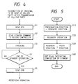
- Fig. 4 is a flow chart showing an operation of the main controller 1
- Fig. 5 is a flow chart showing an operation of the record controller 6.
- Fig. 4 is a flow chart of the main controller when polling is successively started immediately after completion of transmission.
- a DTC digital transmission command signal
- the DTC is a signal for instructing a station on the other end of a line to transmit image data when the own apparatus receives a signal DIS (digital identification signal) for informing functions of the station on the other end of a line and detects the presence of an original after completion of transmission. Thereafter, since the own apparatus becomes a receiving station, the DTC has the same information as the DIS.
- the station on the other end of the line sends a signal DCS for instructing a reception mode, and a signal TCF for checking if there is a transmission error before image data is transmitted.
- step S2 a head standby command is given to the own record controller 6, and training for reception is performed in step S3.
- step S4 head standby end information from the record controller 6 is waited.
- step S5 a CFR (check for reception ready signal) is sent, and an image data reception operation is then started. Note that the CFR is a signal for informing that the receiving station is ready to receive the image data.
- Fig. 5 is a flow chart of the record controller 6 which has received the head standby command output from the main controller 1 in step S2.
- step S10 the head is shifted from the preservation position to the recovery position. After the position of the head is checked by the sensor, an ink supply or ink idle ejection operation is performed in step S20.
- step S30 the head is shifted from the recovery position to the print position. In some cases, a wiping operation for removing an ink attached to nozzle ports is required.
- the print position sensor of the head is turned on, completion of a standby operation is informed to the main controller in Step S40.
- the head standby operation is performed by the record controller 6.
- these control operations may be performed by the main controller.
- the head standby operation is performed simultaneously with transmission of the DTC after completion of transmission thereof.
- the standby operation may be started.
- the standby operation can be similarly performed.
- the head standby operation is started in response to transmission of a digital transmission command signal.
- reception can be efficiently performed even when a preservation or recovery operation is required like in an ink-jet system.
- a recording operation is performed by a bubble-jet system. Any other systems may be employed, as a matter of course.
- the recording head is not limited to a full-multi type recording head.
- a head which serially scans a recording member to perform image recording may be employed.
- the standby operation including the recovery operation is performed in synchronism with transmission of the DTC.
- the present invention is not limited to this.
- the standby operation may be started in synchronism with reception of a DCS or TCF or transmission of a CFR.
Landscapes
- Ink Jet (AREA)
- Fax Reproducing Arrangements (AREA)
- Accessory Devices And Overall Control Thereof (AREA)
- Character Spaces And Line Spaces In Printers (AREA)
- Facsimiles In General (AREA)
Claims (9)
- Bildübertragungsvorrichtung zum Aufzeichnen eines Bildes entsprechend empfangenen Daten auf einem Aufzeichnungsmedium unter Verwendung eines Aufzeichnungskopfes (6-a) mit einer Vielzahl von Aufzeichnungselementen zum Ausstoßen von Tintentröpfchen, mit
einer Übertragungseinrichtung (2, 3) zur Übertragung mit einer Partnerstation zum Senden bzw. Empfangen von vorbestimmten, mit der Übertragung verbundenen Verfahrenssignalen (DIS, DTC, DCS, TCF, CFR) und Bilddaten,
einer ersten Steuereinrichtung (1) zum Steuern eines Übertragungsvorgangs der Übertragungseinrichtung, wobei die erste Steuereinrichtung (1) veranlaßt, daß eine Übertragungsart nach Empfang eines Verfahrenssignals (DCS), das das Vorhandensein einer von der Partnerstation nach Anruf bei der Partnerstation zu übertragenden Vorlage anzeigt, zu einer Empfangsart wechselt,
einer Wiederherstellvorrichtung (6-e) zum Durchführen eines Wiederherstellvorgangs zum Wiederherstellen eines Tintenausstoßzustands des Aufzeichnungskopfes und
einer zweiten Steuereinrichtung (6) zum Steuern einer Arbeitsweise der Wiederherstellvorrichtung,
dadurch gekennzeichnet, daß
die zweite Steuereinrichtung (6) eine Einrichtung zum Erfassen der Übertragung eines vorbestimmten Verfahrenssignals in Form eines Übertragungs-Befehlssignals (DTC) oder zum Empfangen des Verfahrenssignals und zum Auslösen der Arbeitsweise der Wiederherstellvorrichtung zum Ausführen des Wiederherstellvorgangs enthält, bevor die Übertragungseinrichtung nach dem Empfang des Verfahrenssignals (DTC, DCS) die Bilddaten empfängt. - Bildübertragungsvorrichtung nach Anspruch 1, dadurch gekennzeichnet, daß die erste Steuereinrichtung (1) ein vorbestimmtes Signal (1) zu der zweiten Steuereinrichtung (6) nach Übertragung des Verfahrenssignals (DTC) ausgibt und die zweite Steuereinrichtung verursacht, daß die Wiederherstellvorrichtung den Wiederherstellvorgang entsprechend dem vorbestimmten Signal ausführt.
- Bildübertragungsvorrichtung nach Anspruch 2, dadurch gekennzeichnet, daß die erste Steuereinrichtung das vorbestimmte Verfahrenssignal (DTC) nach Empfang eines anderen Verfahrenssignals (DIS), das das Vorhandensein einer Vorlage anzeigt, zu der Partnerstation sendet.
- Bildübertragungsvorrichtung nach Anspruch 3, dadurch gekennzeichnet, daß das vorbestimmte Verfahrenssignal (DTC) ein Signal zum Befehlen der Partnerstation ist, Daten zu übertragen.
- Bildübertragungsvorrichtung nach einem der Ansprüche 1 bis 4, dadurch gekennzeichnet, daß die erste Steuereinrichtung der Partnerstation ein Verfahrenssignal (CFR) sendet, das die Empfangsbereitschaft nach Abschluß des Wiederherstellvorgangs anzeigt.
- Bildübertragungsvorrichtung nach einem der Ansprüche 1 bis 5, dadurch gekennzeichnet, daß die Wiederherstellvorrichtung den Wiederherstellvorgang durch Zuführen von Tinte zu dem Aufzeichnungskopf durchführt.
- Bildübertragungsvorrichtung nach einem der Ansprüche 1 bis 5, dadurch gekennzeichnet, daß die Wiederherstellvorrichtung den Wiederherstellvorgang dadurch durchführt, daß sie den Aufzeichnungskopf veranlaßt, einen Leerlaufausstoß von Tintentröpfchen auszuführen, der nicht zur Aufzeichnung dient.
- Bildübertragungsvorrichtung nach einem der Ansprüche 1 bis 7, dadurch gekennzeichnet, daß der Aufzeichnungskopf mit den Aufzeichnungselementen einer Zeile ausgestattet ist, die einem Aufzeichnungsabschnitt des Aufzeichnungsmediums entspricht.
- Bildübertragungsvorrichtung nach einem der Ansprüche 1 bis 8, dadurch gekennzeichnet, daß der Aufzeichnungskopf durch Verursachen einer Veränderung des Zustands der Tinte unter Verwendung von von den Aufzeichnungselementen abgegebener Wärmeenergie Tintentröpfchen ausstößt.
Applications Claiming Priority (2)
| Application Number | Priority Date | Filing Date | Title |
|---|---|---|---|
| JP139317/89 | 1989-06-02 | ||
| JP1139317A JP2719634B2 (ja) | 1989-06-02 | 1989-06-02 | 画像通信装置 |
Publications (3)
| Publication Number | Publication Date |
|---|---|
| EP0401026A2 EP0401026A2 (de) | 1990-12-05 |
| EP0401026A3 EP0401026A3 (de) | 1991-07-10 |
| EP0401026B1 true EP0401026B1 (de) | 1995-04-12 |
Family
ID=15242493
Family Applications (1)
| Application Number | Title | Priority Date | Filing Date |
|---|---|---|---|
| EP90305959A Expired - Lifetime EP0401026B1 (de) | 1989-06-02 | 1990-05-31 | Bildübertragungsvorrichtung |
Country Status (4)
| Country | Link |
|---|---|
| US (1) | US5229792A (de) |
| EP (1) | EP0401026B1 (de) |
| JP (1) | JP2719634B2 (de) |
| DE (1) | DE69018515T2 (de) |
Families Citing this family (9)
| Publication number | Priority date | Publication date | Assignee | Title |
|---|---|---|---|---|
| JP2786255B2 (ja) * | 1989-06-02 | 1998-08-13 | キヤノン株式会社 | 画像通信装置 |
| EP0610959B1 (de) * | 1989-11-22 | 1997-07-23 | Canon Kabushiki Kaisha | Farbstrahlaufzeichnungsvorrichtung |
| DE69125515T2 (de) * | 1990-02-23 | 1997-09-04 | Canon Kk | Bildübertragungsgerät |
| EP0447262A1 (de) * | 1990-03-16 | 1991-09-18 | Canon Kabushiki Kaisha | Faksimilegerät |
| JP3441767B2 (ja) * | 1992-07-28 | 2003-09-02 | キヤノン株式会社 | 画像記録装置 |
| JPH0698119A (ja) * | 1992-07-28 | 1994-04-08 | Canon Inc | 画像記録装置 |
| US5374709A (en) * | 1992-10-23 | 1994-12-20 | Phillips Petroleum Company | Production of granular poly(arylene sulfide) polymers containing reduced amounts of oligomers |
| JP4233632B2 (ja) | 1997-06-11 | 2009-03-04 | キヤノンファインテック株式会社 | 画像形成方法およびその装置 |
| EP0884185B1 (de) * | 1997-06-11 | 2002-10-16 | Canon Aptex Inc. | Bilderzeugungsverfahren und Bilderzeugungsgerät dafür |
Family Cites Families (14)
| Publication number | Priority date | Publication date | Assignee | Title |
|---|---|---|---|---|
| JPS5932313B2 (ja) * | 1976-06-07 | 1984-08-08 | コニカ株式会社 | インクジエツト記録装置のインク通路洗浄方法 |
| JPS5626254U (de) * | 1979-08-08 | 1981-03-11 | ||
| US4376283A (en) * | 1980-11-03 | 1983-03-08 | Exxon Research And Engineering Co. | Method and apparatus for using a disposable ink jet assembly in a facsimile system and the like |
| US4333088A (en) * | 1980-11-03 | 1982-06-01 | Exxon Research & Engineering Co. | Disposable peristaltic pump assembly for facsimile printer |
| JPS58119867A (ja) * | 1982-01-12 | 1983-07-16 | Canon Inc | インクジェット装置 |
| US4558332A (en) * | 1982-04-02 | 1985-12-10 | Canon Kabushiki Kaisha | Ink jet printer |
| JPS58183265A (ja) * | 1982-04-20 | 1983-10-26 | Fujitsu Ltd | インクジェット・ヘッドの動作確認装置 |
| JPS60219060A (ja) * | 1984-04-17 | 1985-11-01 | Canon Inc | 液体噴射記録装置 |
| JPS6319968A (ja) * | 1986-07-12 | 1988-01-27 | Ricoh Co Ltd | フアクシミリ装置 |
| JPS6348043A (ja) * | 1986-08-15 | 1988-02-29 | Ricoh Co Ltd | デ−タ通信装置 |
| JPS63209364A (ja) * | 1987-02-26 | 1988-08-30 | Canon Inc | 記録装置 |
| US4897831A (en) * | 1987-03-02 | 1990-01-30 | Canon Kabushiki Kaisha | Data transmission/reception apparatus |
| US4931955A (en) * | 1987-04-28 | 1990-06-05 | Juki Corporation | Ink jet printing apparatus with preprinting jet purging mechanism |
| JPS649759A (en) * | 1987-07-03 | 1989-01-13 | Canon Kk | Recorder |
-
1989
- 1989-06-02 JP JP1139317A patent/JP2719634B2/ja not_active Expired - Fee Related
-
1990
- 1990-05-31 EP EP90305959A patent/EP0401026B1/de not_active Expired - Lifetime
- 1990-05-31 DE DE69018515T patent/DE69018515T2/de not_active Expired - Fee Related
- 1990-06-01 US US07/531,590 patent/US5229792A/en not_active Expired - Lifetime
Also Published As
| Publication number | Publication date |
|---|---|
| JP2719634B2 (ja) | 1998-02-25 |
| DE69018515T2 (de) | 1995-09-14 |
| DE69018515D1 (de) | 1995-05-18 |
| EP0401026A2 (de) | 1990-12-05 |
| EP0401026A3 (de) | 1991-07-10 |
| US5229792A (en) | 1993-07-20 |
| JPH036170A (ja) | 1991-01-11 |
Similar Documents
| Publication | Publication Date | Title |
|---|---|---|
| EP0401024B1 (de) | Bildübertragungsvorrichtung | |
| EP1393913B1 (de) | Druckgerät und Steuerungsverfahren zum Vorab-Ausstossen | |
| EP0469619B1 (de) | Wischvorrichtung und Verfahren an einem Aufzeichnungskopf eines Tintenaufzeichnungsgerätes | |
| JP2002225243A (ja) | インクジェット記録装置およびインクジェット記録方法 | |
| EP0401026B1 (de) | Bildübertragungsvorrichtung | |
| JP4363510B2 (ja) | インクジェットプリントシステム | |
| JPH03245667A (ja) | ファクシミリ装置 | |
| US6447096B1 (en) | Ink jet recording apparatus and recovery method therefor | |
| JP2844204B2 (ja) | インクジェット記録装置の回復方法 | |
| US6238034B1 (en) | Ink-jet recording methods and apparatuses | |
| EP0401025B1 (de) | Bildübertragungsvorrichtung | |
| EP0443716B1 (de) | Bildübertragungsgerät | |
| JPH0640027A (ja) | 液体噴射装置 | |
| US5877782A (en) | Image recording apparatus | |
| JP3264594B2 (ja) | 記録装置 | |
| JP2001158153A (ja) | 記録装置 | |
| JPH03234621A (ja) | 記録装置 | |
| JP2001146042A (ja) | 多機能記録装置 | |
| JPH05293967A (ja) | インクジェット記録装置 | |
| JPH03267865A (ja) | カラー画像通信装置及び方法 | |
| JP2007245584A (ja) | インクジェット記録装置およびインクジェット記録方法 | |
| JPH06284238A (ja) | 画像記録装置 | |
| JPH03267868A (ja) | カラーファクシミリ装置 | |
| JPH04147864A (ja) | インクジエツト記録装置 | |
| JPH09123483A (ja) | カラーインクジェット式記録装置 |
Legal Events
| Date | Code | Title | Description |
|---|---|---|---|
| PUAI | Public reference made under article 153(3) epc to a published international application that has entered the european phase |
Free format text: ORIGINAL CODE: 0009012 |
|
| AK | Designated contracting states |
Kind code of ref document: A2 Designated state(s): DE FR GB IT NL |
|
| 17P | Request for examination filed |
Effective date: 19901231 |
|
| PUAL | Search report despatched |
Free format text: ORIGINAL CODE: 0009013 |
|
| AK | Designated contracting states |
Kind code of ref document: A3 Designated state(s): DE FR GB IT NL |
|
| 17Q | First examination report despatched |
Effective date: 19930211 |
|
| GRAA | (expected) grant |
Free format text: ORIGINAL CODE: 0009210 |
|
| AK | Designated contracting states |
Kind code of ref document: B1 Designated state(s): DE FR GB IT NL |
|
| REF | Corresponds to: |
Ref document number: 69018515 Country of ref document: DE Date of ref document: 19950518 |
|
| ET | Fr: translation filed | ||
| ITF | It: translation for a ep patent filed | ||
| PLBE | No opposition filed within time limit |
Free format text: ORIGINAL CODE: 0009261 |
|
| STAA | Information on the status of an ep patent application or granted ep patent |
Free format text: STATUS: NO OPPOSITION FILED WITHIN TIME LIMIT |
|
| 26N | No opposition filed | ||
| REG | Reference to a national code |
Ref country code: GB Ref legal event code: IF02 |
|
| PGFP | Annual fee paid to national office [announced via postgrant information from national office to epo] |
Ref country code: NL Payment date: 20040517 Year of fee payment: 15 |
|
| PG25 | Lapsed in a contracting state [announced via postgrant information from national office to epo] |
Ref country code: NL Free format text: LAPSE BECAUSE OF NON-PAYMENT OF DUE FEES Effective date: 20051201 |
|
| NLV4 | Nl: lapsed or anulled due to non-payment of the annual fee |
Effective date: 20051201 |
|
| PGFP | Annual fee paid to national office [announced via postgrant information from national office to epo] |
Ref country code: DE Payment date: 20080531 Year of fee payment: 19 |
|
| PGFP | Annual fee paid to national office [announced via postgrant information from national office to epo] |
Ref country code: IT Payment date: 20080521 Year of fee payment: 19 |
|
| PGFP | Annual fee paid to national office [announced via postgrant information from national office to epo] |
Ref country code: GB Payment date: 20080520 Year of fee payment: 19 |
|
| GBPC | Gb: european patent ceased through non-payment of renewal fee |
Effective date: 20090531 |
|
| REG | Reference to a national code |
Ref country code: FR Ref legal event code: ST Effective date: 20100129 |
|
| PG25 | Lapsed in a contracting state [announced via postgrant information from national office to epo] |
Ref country code: FR Free format text: LAPSE BECAUSE OF NON-PAYMENT OF DUE FEES Effective date: 20090602 |
|
| PGFP | Annual fee paid to national office [announced via postgrant information from national office to epo] |
Ref country code: FR Payment date: 20080424 Year of fee payment: 19 |
|
| PG25 | Lapsed in a contracting state [announced via postgrant information from national office to epo] |
Ref country code: GB Free format text: LAPSE BECAUSE OF NON-PAYMENT OF DUE FEES Effective date: 20090531 |
|
| PG25 | Lapsed in a contracting state [announced via postgrant information from national office to epo] |
Ref country code: DE Free format text: LAPSE BECAUSE OF NON-PAYMENT OF DUE FEES Effective date: 20091201 |
|
| PG25 | Lapsed in a contracting state [announced via postgrant information from national office to epo] |
Ref country code: IT Free format text: LAPSE BECAUSE OF NON-PAYMENT OF DUE FEES Effective date: 20090531 |