EP0401042B1 - Groupe d'éléments de masquage et méthode pour les fixer - Google Patents
Groupe d'éléments de masquage et méthode pour les fixer Download PDFInfo
- Publication number
- EP0401042B1 EP0401042B1 EP90306013A EP90306013A EP0401042B1 EP 0401042 B1 EP0401042 B1 EP 0401042B1 EP 90306013 A EP90306013 A EP 90306013A EP 90306013 A EP90306013 A EP 90306013A EP 0401042 B1 EP0401042 B1 EP 0401042B1
- Authority
- EP
- European Patent Office
- Prior art keywords
- masking
- group
- cylinder
- members
- outlet
- Prior art date
- Legal status (The legal status is an assumption and is not a legal conclusion. Google has not performed a legal analysis and makes no representation as to the accuracy of the status listed.)
- Expired - Lifetime
Links
Images




Classifications
-
- B—PERFORMING OPERATIONS; TRANSPORTING
- B05—SPRAYING OR ATOMISING IN GENERAL; APPLYING FLUENT MATERIALS TO SURFACES, IN GENERAL
- B05B—SPRAYING APPARATUS; ATOMISING APPARATUS; NOZZLES
- B05B12/00—Arrangements for controlling delivery; Arrangements for controlling the spray area
- B05B12/16—Arrangements for controlling delivery; Arrangements for controlling the spray area for controlling the spray area
- B05B12/20—Masking elements, i.e. elements defining uncoated areas on an object to be coated
Definitions
- the present invention relates to masking members to protect parts of an article such as a car body from surface treatment such as coating, plating, vacuum evaporation, phosphatizing and the like.
- the present invention relates to a method of attaching masking members, and a method of protecting articles using the masking members.
- said parts of said surface of said article may be covered and protected with a masking member.
- said parts may be parts on which brackets, frames and the like are attached, or holes such as water ejecting holes, shaft holes, harness holes and the like.
- a coating agent such as a polyvinylchloride-sol, a tar-urethane mixture and the like
- the surface treatment leaks from said holes to waste said coating agent and further it may be that said coating agent fills in said holes or stains the inside of said holes.
- said masking members must be attached and removed in a short time.
- a panel type masking member having an adhesive layer on one side has been provided (as disclosed in US-A-4,835,026). Said masking member is used to protect a flat surface part of an article and said masking member is attached to said flat surface part by said adhesive layer manually.
- An object of the present invention is to allow saving of labour and time in attaching of said masking member.
- the invention makes attaching of said masking members suitable for automatic operation, in particular.
- a group of masking members consisting of a plural number of generally flat masking members each of which has an adhesive layer on one side, characterised by said masking members being placed one upon another and separately adhered to each other by said adhesive layers, wherein the contact area available to be between a masking member and said part of said article which is to be protected is larger than the contact area between adjacent masking members.
- the invention also provides a method of attaching masking members of such a group of masking members to a part of an article which is to be protected comprising putting said group of masking members in a masking tool which comprises a cylinder having an inlet at one end and an outlet at the other end, and a transporting means for said group wherein said adhesive layer of each masking member faces in the direction of the outlet of said cylinder, successively transporting said group to the outlet of said cylinder by operation of said transporting means to put out that masking member located in the lowest position of said group from the outlet of said cylinder, and attaching said masking member to said part of an article by said adhesive layer thereof.
- the invention provides a method of treating a surface by applying to a part of the surface at least one masking member from such a group of masking members or attaching a masking member using the above method, and applying coating or other treatment to the surface so that the said part is not coated or treated and removing the masking member.
- Fig. 1 to Fig. 7 relate to a first embodiment of the present invention.
- a flat type masking member (111) has a smooth and flat surface of the upper side (113) and an adhesive layer (114) is formed on the lower side (112) and a plural number of said masking members (111) are placed one upon another to form a group of masking members (117) as shown in Fig. 1.
- said masking members (111) are mutually adhered by said adhesive layer (114) thereof.
- a masking tool (120) comprises a cylinder (121) having an inlet (122) at one end and an outlet (123) at the other end, a friction sheet (129) attached to the inside of said cylinder (121), and a piston (124) as a transporting means.
- Said piston (124) is inserted into said cylinder (121) from said inlet (122) thereof and a handle (126) which is rotatably attached on said inlet (122) by an axis (125) is connected to the piston rod (124A) of said piston (124) wherein a pin (128) of said piston rod (124A) is inserted in a groove (127A) of a bracket (127) of said handle (126).
- Said group of masking members (117) is put into said cylinder (121) of said masking tool (120) and said adhesive layer (114) of each masking member (111) faces in a direction to the outlet (123) of said cylinder (121) and said piston (124) of said masking tool (120) contacts with the upper side (113) of one of said masking members (111) which is located in the upper most position of said group of masking members (117) as shown in Fig. 2.
- Said masking members (111) of said group (117) are successively transported from the inlet (122) to the outlet (123) in said cylinder (121) by operation of said piston (124) by said handle (126).
- Said handle may be operated by hand, oil pressure, electromagnetic means, and the like.
- one of said masking members (111) located in the lowest position of said group (117) is pushed out from the outlet (123) of said cylinder (121) by said operation of said piston (124) and attached to a part (131) having a flat surface of an article (130) by said adhesive layer (114) of said masking member (111) as shown in Fig. 2.
- said masking member (111) is separated from said group (115) in said cylinder (121) of said masking tool (120) as shown in Fig. 3. Adhesion between the member and surface to be protected is stronger than that between masking members of the group.
- said masking tool (120) is operated by a robot and in this case, said masking members (111) are automatically attached to said part (131).
- said piston (124) may be directly operated by a pressure oil cylinder, an electromagnetic cylinder, and the like instead of said handle (126).
- Said masking member (111) is made of a material, such as a foam of a plastic or a rubber such as polystyrene, polyethylene, polypropylene, ethylene-propylene copolymer, polyvinyl-chloride, polyvinylidene chloride, polymethacrylate, styrene-butadiene copolymer, acrylonitrile-butadiene copolymer, polybutadine polyisoprene, polyisobutylene, polychloroprene, isopreneisobutylene copolymer, natural rubber, polyurethane, melamine resin, urea resin, phenol resin, epoxy resin and the like; a mixture of said plastic or said rubber with a filler such as calcium carbonate, talc, bentonite, fly ash, blast furnace slag, and the like; or composite material consisting of a plural number of materials selected from the group of said materials.
- a material such as a foam
- the peeling strength between said masking member (111) and said part (131) of said article (13) be made larger than the peeling strength between a pair of said masking members (111), (111) mutually in contact.
- the contact area between said masking member (111) and said part (131) should be larger than the contact area between a pair of said masking members (111), (111) mutually in contact, or the bonding strength between said masking member (111) and said part (131) should be larger than the bonding strength between a pair of said masking members (111), (111) mutually in contact.
- said adhesive layer (114A) is fully formed on the lower side (112A) of said masking member (111A) and a dent (115A) having a smooth and flat surface (116A) in the bottom thereof is formed on the upper side (113A) of said masking member (111A) as shown in Fig.
- said adhesive layer (114B) is partially formed on the circumference of the lower side (112B) of said masking member (111B) and a smooth and flat surface is fully formed on the upper side (113B) wherein four projections (115B) are respectively formed on the four corners of said upper side (113B) as shown in Fig. 4B and Fig. 4C, or said adhesive layer (114C) is fully formed on the lower side (112C) of said masking member (111C) and a projection (115C) having a smooth and flat surface (116C) is formed on the upper side (113C) of said masking member (111C) as shown in Fig. 4D.
- FIG. 5 there is provided another group of masking members (117D) consisting of a plural number of flat type masking members (111D) each of which has an adhesive layer (114D) on the lower side (112D) thereof and a release sheet (115D) on the upper side (113D).
- Said release sheet (115D) may be such as polyethylene sheet, polypropylene sheet and the like.
- said release sheet (115D) is intermediate between a pair of said masking members (111D), (111D) mutually in contact and consequently one masking member (111D) may be easily separated from another masking member (111D).
- a plural number of panels (110) are placed one upon another to form an accumulation of said panels (118) as shown in Fig. 6.
- Each of said panels (110) has an adhesive layer (114A) on the lower side and a plural number of dents (115A) arranged along the length and breadth on the upper side.
- Said group of said panels (118) is then cut along the dotted lines shown as in Fig. 6 by employing a heated wire, a cutter, an ultrasonic wave-cutter, a water-jet and the like to obtain said group of masking members (117).
- said masking members (111D) is respectively made of thermoplastic material
- said masking members (111D) are mutually attached by the melted side surface thereof by contacting with said heated wire besides, said masking member (111D) is mutually adhered by said adhesive layer (114D) thereof.
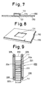
- said masking member (111) is attached to said part (131) of said article (130) by said adhesive layer (114) formed on the lower side (112) of said masking member (111) and after this, a paint such as a polyvinylchloride-sol, a urethane resin, an asphalt, a rubber-asphalt mixture, a tar-urethane mixture and the like is coated on the surface of said article to form a coating layer (150) as shown in Fig. 7. After said coating, said masking member (111) is removed from said part (131) as shown in Fig. 8.
- a paint such as a polyvinylchloride-sol, a urethane resin, an asphalt, a rubber-asphalt mixture, a tar-urethane mixture and the like is coated on the surface of said article to form a coating layer (150) as shown in Fig. 7.
- said masking member (111) is removed from said part (131) as shown in Fig. 8.
- a masking tool (220) of this embodiment comprises a cylinder (221) having an inlet (222) at one end and an outlet (223) at the other end, and a pair of endless belts (224), (224) acting as a transporting means.
- Each of said endless belts (224), (224) is suspended on a pair of rollers (225), (226) wherein one set of said rollers (225) is rotatably attached to the inlet (222) of said cylinder (221) and the other set of said rollers (226) are rotatably attached to the outlet (223) of said cylinder (221).
- Said endless belts (224), (224) are respectively made of a friction material such as a rubber, a cloth having a flocking layer, and the like.
- Said group of said masking members (117) of the first embodiment is put into said cylinder (221) of said masking tool (220) wherein said group of masking members (117) is pressed between a pair of said endless belts (224), (224) in said cylinder (221) of said masking tool (220).
- Said group of masking members (117) are successively transported from the inlet (222) to the outlet (223) in said cylinder (221) by driving said rollers (225), (226) by a driving means such as a motor and the like to attach one of said masking members (111) located in the lowest position of said group (117) to a part of an article as same as the first embodiment.
- Fig. 10 to Fig. 12 relate to a third embodiment of the present invention.
- a sucking tool (140) as shown in Fig. 10 is used.
- Said sucking tool (140) comprises an oil pressure cylinder (141), a pipe (143) attached at the end of the piston rod (142) of said oil pressure cylinder (141), a sucker (144) attached at the end of said pipe (143), and a vacuum tube (145) in which a trap intermediates.
- Said sucker (144) is made of a rubber, a plastics, a metal, and the like.
- Said sucker (144) of said sucking tool (140) is contacted with the upper side (113) of one of said masking members (111) which is located in the uppermost position of said group of masking members (117) in said masking tool (120) turned upside down as shown in Fig. 10.
- Said masking member (111) is sucked by said sucker (144) of said sucking tool (140) and then transported to said part (131) of said article (130) to attach said masking member (111) to said part (131) by said adhesive layer (114) thereof before coating as shown in Fig. 12.
- Said masking member (111) attached to said part (131) is separated from said sucker (144) of said sucking tool (140) by opening said vacuum tube (145) in the atmosphere or by putting the air into said vacuum tube (145).
- said group of masking members (117) is put into said cylinder (121) facing said adhesive layer (114) of each masking member (111) of said group (117) in a direction to the inlet (122) of said cylinder (121).
Landscapes
- Details Or Accessories Of Spraying Plant Or Apparatus (AREA)
Claims (8)
- Groupe d'éléments de masquage (111) consistant en une pluralité d'éléments de masquage plat d'une façon générale, comportant chacun une couche adhésive (114) sur une de ses faces, caractérisé par le fait que lesdits éléments de masquage sont placés les uns sur les autres et sont collés séparément l'un sur l'autre par lesdites couche adhésives (114), la zone de contact disponible pour être placée entre un élément de masquage (111) et une partie (131) d'un article (130) qui doit être protégé étant plus grande que la zone de contact entre les éléments de masquage adjacents (111).
- Procédé de fixation d'éléments de masquage d'un groupe selon la revendication 1 à une partie d'un article qui doit être protégé, ce procédé consistant à placer ledit groupe d'éléments de masquage (111) dans un outil de masquage qui comprend un cylindre (121, 221) comportant un entrée (122, 222) à une de ses extrémités et une sortie (123, 223) à son autre extrémité, et un moyen de transport pour ledit groupe, dans lequel ladite couche adhésive (114) de chaque élément de masquage est orientée en direction de la sortie (123, 223) dudit cylindre (121, 221), à transporter successivement ledit groupe jusqu'à la sortie (123, 223) dudit cylindre (121, 221) par actionnement dudit moyen de transport pour expulser l'élément de masquage (111) situé dans la position la plus basse dudit groupe par la sortie (123, 223) dudit cylindre (121, 221), et à fixer ledit élément de masquage (111) à ladite partie (131) d'un article (130) par ladite couche adhésive (114) de cet élément de masquage.
- Procédé de fixation d'éléments de masquage d'un groupe selon la revendication 1 à une partie d'un article qui doit être protégé, ce procédé consistant à placer ladite accumulation d'éléments de masquage dans un outil de masquage (120, 220) qui comprend un cylindre (121, 221) comportant une entrée (122, 222) à une de ses extrémités et une sortie (123, 223) à son autre extrémité et un moyen de transport pour ledit groupe, dans lequel ladite couche adhésive (114) de chaque élément de masquage (111) est orientée en direction de l'entrée (122, 222) dudit cylindre (121, 221), à transporter successivement ledit groupe jusqu'à la sortie (123, 223) dudit cylindre (121, 221) par actionnement dudit moyen de transport pour pousser l'un desdits éléments de masquage situé à l'extrémité de sortie dudit groupe hors de la sortie (123, 223) dudit cylindre (121, 221), à aspirer vers le haut ledit élément de masquage à l'aide d'un dispositif d'aspiration (144) pour séparer ledit élément de masquage (111) dudit groupe et à transporter ledit élément de masquage (111) jusqu'à une partie (131) d'un article (130) pour fixer ledit élément de masquage (111) à ladite partie à l'aide de ladite couche adhésive (114) de ce dernier.
- Procédé de fixation d'éléments de masquage selon la revendication 2 ou 3, dans lequel ledit moyen de transport est un piston (124) qui porte contre la face supérieure (113) d'un desdits éléments de masquage (111) situé dans la position la plus haute dudit groupe d'éléments de masquage (111) dans ledit cylindre (121) dudit outil de masquage (120).
- Procédé de fixation d'éléments de masquage selon la revendication 2 ou 3, dans lequel ledit moyen de transport est une paire de courroies sans fin (224) exerçant une pression sur ledit groupe d'éléments de masquage (111) dans ledit cylindre (221) dudit outil de masquage (220).
- Combinaison d'un groupe d'éléments de masquage (111) selon la revendication 1 et d'un outil de masquage (120, 220) comprenant un cylindre (121, 122) comportant une entrée (122, 222) à une de ses extrémités et une sortie (123, 223) à son autre extrémité, et un moyen de transport pour ledit groupe dans lequel ladite couche adhésive (114) de chaque élément de masquage (111) est orientée en direction de la sortie (123, 223) dudit cylindre (121, 221).
- Combinaison d'un groupe d'éléments de masquage (111) selon la revendication 1 et d'un outil de masquage (120, 220) qui comprend un cylindre (121, 221) comportant une entrée (122, 222) à une de ses extrémités et une sortie (123, 223) à son autre extrémité et un moyen de transport pour ledit groupe, dans lequel ladite couche adhésive (114) de chaque élément de masquage (111) est orientée en direction de l'entrée dudit cylindre, et un dispositif d'aspiration (144) pour séparer ledit élément de masquage (111) dudit groupe et transporter ledit élément de masquage (111) jusqu'à une partie (131) d'un article (130) pour fixer ledit élément de masquage (111) à ladite partie (131) par ladite couche adhésive (114).
- Procédé pour traiter une surface en appliquant à une partie de la surface au moins un élément de masquage (111) à partir d'un groupe selon la revendication 1 ou en utilisant le procédé selon la revendication 2, 3, 4 ou 5 et en appliquant 'un revêtement ou un autre traitement à la surface de telle sorte que ladite partie ne soit pas revêtue ou traitée et en enlevant ledit élément de masquage (111).
Applications Claiming Priority (4)
| Application Number | Priority Date | Filing Date | Title |
|---|---|---|---|
| JP64970/89U | 1989-06-02 | ||
| JP6497089 | 1989-06-02 | ||
| JP1180105A JPH03143566A (ja) | 1989-06-02 | 1989-07-11 | マスキング材積重ね物およびマスキング材の取付方法 |
| JP180105/89 | 1989-07-11 |
Publications (3)
| Publication Number | Publication Date |
|---|---|
| EP0401042A2 EP0401042A2 (fr) | 1990-12-05 |
| EP0401042A3 EP0401042A3 (fr) | 1991-08-14 |
| EP0401042B1 true EP0401042B1 (fr) | 1994-09-21 |
Family
ID=26406119
Family Applications (1)
| Application Number | Title | Priority Date | Filing Date |
|---|---|---|---|
| EP90306013A Expired - Lifetime EP0401042B1 (fr) | 1989-06-02 | 1990-06-01 | Groupe d'éléments de masquage et méthode pour les fixer |
Country Status (3)
| Country | Link |
|---|---|
| EP (1) | EP0401042B1 (fr) |
| CA (1) | CA2017892A1 (fr) |
| DE (1) | DE69012652T2 (fr) |
Families Citing this family (1)
| Publication number | Priority date | Publication date | Assignee | Title |
|---|---|---|---|---|
| CN107876259B (zh) * | 2017-12-19 | 2023-10-31 | 瑞鼎机电科技(昆山)有限公司 | 工件双面喷涂遮挡装置 |
Family Cites Families (1)
| Publication number | Priority date | Publication date | Assignee | Title |
|---|---|---|---|---|
| GB2189768B (en) * | 1986-05-01 | 1990-07-11 | Avery International Corp | Pressure sensitive labels in block form |
-
1990
- 1990-05-30 CA CA002017892A patent/CA2017892A1/fr not_active Abandoned
- 1990-06-01 EP EP90306013A patent/EP0401042B1/fr not_active Expired - Lifetime
- 1990-06-01 DE DE69012652T patent/DE69012652T2/de not_active Expired - Fee Related
Also Published As
| Publication number | Publication date |
|---|---|
| DE69012652T2 (de) | 1995-01-26 |
| EP0401042A3 (fr) | 1991-08-14 |
| DE69012652D1 (de) | 1994-10-27 |
| EP0401042A2 (fr) | 1990-12-05 |
| CA2017892A1 (fr) | 1990-12-02 |
Similar Documents
| Publication | Publication Date | Title |
|---|---|---|
| US5091220A (en) | Method of surface treatment whereby a mask is attached to the work by an adhesive, the work is surface treated, and the mask is removed by suction | |
| DE69915387D1 (de) | Flexible, thermoplastische hochtemperaturbeständige verbundwerkstoffe für die antriebsflächen eines förderbandes | |
| EP1484173A3 (fr) | Procédé pour la préparation d'un article | |
| EP0713759A3 (fr) | ||
| US5585179A (en) | Working protection cover and parts thereof, and method of manufacturing the working protection cover | |
| JPH06506870A (ja) | 柔軟なストリップを使用するマスキング方法 | |
| US8251010B2 (en) | Masking material for painting | |
| US5193716A (en) | Masking method | |
| CA1038420A (fr) | Garniture interieure collante pour toiture de vehicule automobile | |
| JP4180643B1 (ja) | 廃棄物処理における廃棄物削減方法 | |
| EP0401042A2 (fr) | Groupe d'éléments de masquage et méthode pour les fixer | |
| AU6892487A (en) | Making rubber gloves | |
| CA2062960A1 (fr) | Methode de masquage | |
| EP0400667A2 (fr) | Outil et procédé de masquage | |
| US20080113150A1 (en) | Suction tape | |
| EP0483377A1 (fr) | Materiau de masquage | |
| EP0384695A1 (fr) | Elément de cache | |
| EP0406002A2 (fr) | Procédé de traitement de surface | |
| EP0509100A1 (fr) | Materiau de masquage | |
| JPH0338282A (ja) | 表面処理方法 | |
| JPH03221168A (ja) | 表面処理方法 | |
| EP1190846A3 (fr) | Matière composite à base de caoutchouc et article en caoutchouc utilisant ledit composite | |
| EP0606694A1 (fr) | Masque | |
| WO1991012089A1 (fr) | Procede de pose ou de depose d'une matiere de masquage | |
| JPH03170692A (ja) | 表面処理方法 |
Legal Events
| Date | Code | Title | Description |
|---|---|---|---|
| PUAI | Public reference made under article 153(3) epc to a published international application that has entered the european phase |
Free format text: ORIGINAL CODE: 0009012 |
|
| AK | Designated contracting states |
Kind code of ref document: A2 Designated state(s): DE FR GB IT SE |
|
| PUAL | Search report despatched |
Free format text: ORIGINAL CODE: 0009013 |
|
| AK | Designated contracting states |
Kind code of ref document: A3 Designated state(s): DE FR GB IT SE |
|
| 17P | Request for examination filed |
Effective date: 19911014 |
|
| 17Q | First examination report despatched |
Effective date: 19920902 |
|
| GRAA | (expected) grant |
Free format text: ORIGINAL CODE: 0009210 |
|
| AK | Designated contracting states |
Kind code of ref document: B1 Designated state(s): DE FR GB IT SE |
|
| ET | Fr: translation filed | ||
| REF | Corresponds to: |
Ref document number: 69012652 Country of ref document: DE Date of ref document: 19941027 |
|
| ITF | It: translation for a ep patent filed | ||
| EAL | Se: european patent in force in sweden |
Ref document number: 90306013.5 |
|
| PG25 | Lapsed in a contracting state [announced via postgrant information from national office to epo] |
Ref country code: GB Effective date: 19950601 |
|
| PG25 | Lapsed in a contracting state [announced via postgrant information from national office to epo] |
Ref country code: SE Effective date: 19950602 |
|
| PLBE | No opposition filed within time limit |
Free format text: ORIGINAL CODE: 0009261 |
|
| STAA | Information on the status of an ep patent application or granted ep patent |
Free format text: STATUS: NO OPPOSITION FILED WITHIN TIME LIMIT |
|
| 26N | No opposition filed | ||
| GBPC | Gb: european patent ceased through non-payment of renewal fee |
Effective date: 19950601 |
|
| PG25 | Lapsed in a contracting state [announced via postgrant information from national office to epo] |
Ref country code: FR Effective date: 19960229 |
|
| PG25 | Lapsed in a contracting state [announced via postgrant information from national office to epo] |
Ref country code: DE Effective date: 19960301 |
|
| EUG | Se: european patent has lapsed |
Ref document number: 90306013.5 |
|
| REG | Reference to a national code |
Ref country code: FR Ref legal event code: ST |
|
| PG25 | Lapsed in a contracting state [announced via postgrant information from national office to epo] |
Ref country code: IT Free format text: LAPSE BECAUSE OF NON-PAYMENT OF DUE FEES;WARNING: LAPSES OF ITALIAN PATENTS WITH EFFECTIVE DATE BEFORE 2007 MAY HAVE OCCURRED AT ANY TIME BEFORE 2007. THE CORRECT EFFECTIVE DATE MAY BE DIFFERENT FROM THE ONE RECORDED. Effective date: 20050601 |