EP0401741A1 - Zweistufige Trockenprimärpumpe - Google Patents
Zweistufige Trockenprimärpumpe Download PDFInfo
- Publication number
- EP0401741A1 EP0401741A1 EP90110602A EP90110602A EP0401741A1 EP 0401741 A1 EP0401741 A1 EP 0401741A1 EP 90110602 A EP90110602 A EP 90110602A EP 90110602 A EP90110602 A EP 90110602A EP 0401741 A1 EP0401741 A1 EP 0401741A1
- Authority
- EP
- European Patent Office
- Prior art keywords
- pump
- screw
- drive
- stage
- screw pump
- Prior art date
- Legal status (The legal status is an assumption and is not a legal conclusion. Google has not performed a legal analysis and makes no representation as to the accuracy of the status listed.)
- Granted
Links
- 238000001816 cooling Methods 0.000 claims description 2
- 230000006835 compression Effects 0.000 description 2
- 238000007906 compression Methods 0.000 description 2
- 230000000694 effects Effects 0.000 description 2
- 239000012530 fluid Substances 0.000 description 2
- 238000010438 heat treatment Methods 0.000 description 2
- 238000005086 pumping Methods 0.000 description 2
- 230000006978 adaptation Effects 0.000 description 1
- 230000033228 biological regulation Effects 0.000 description 1
- 230000015556 catabolic process Effects 0.000 description 1
- 238000006731 degradation reaction Methods 0.000 description 1
- 239000007788 liquid Substances 0.000 description 1
- 230000005012 migration Effects 0.000 description 1
- 238000013508 migration Methods 0.000 description 1
- 230000006641 stabilisation Effects 0.000 description 1
- 238000011105 stabilization Methods 0.000 description 1
- 230000001360 synchronised effect Effects 0.000 description 1
- 230000001052 transient effect Effects 0.000 description 1
- XLYOFNOQVPJJNP-UHFFFAOYSA-N water Substances O XLYOFNOQVPJJNP-UHFFFAOYSA-N 0.000 description 1
Images

Classifications
-
- F—MECHANICAL ENGINEERING; LIGHTING; HEATING; WEAPONS; BLASTING
- F04—POSITIVE - DISPLACEMENT MACHINES FOR LIQUIDS; PUMPS FOR LIQUIDS OR ELASTIC FLUIDS
- F04C—ROTARY-PISTON, OR OSCILLATING-PISTON, POSITIVE-DISPLACEMENT MACHINES FOR LIQUIDS; ROTARY-PISTON, OR OSCILLATING-PISTON, POSITIVE-DISPLACEMENT PUMPS
- F04C28/00—Control of, monitoring of, or safety arrangements for, pumps or pumping installations specially adapted for elastic fluids
- F04C28/02—Control of, monitoring of, or safety arrangements for, pumps or pumping installations specially adapted for elastic fluids specially adapted for several pumps connected in series or in parallel
-
- F—MECHANICAL ENGINEERING; LIGHTING; HEATING; WEAPONS; BLASTING
- F04—POSITIVE - DISPLACEMENT MACHINES FOR LIQUIDS; PUMPS FOR LIQUIDS OR ELASTIC FLUIDS
- F04C—ROTARY-PISTON, OR OSCILLATING-PISTON, POSITIVE-DISPLACEMENT MACHINES FOR LIQUIDS; ROTARY-PISTON, OR OSCILLATING-PISTON, POSITIVE-DISPLACEMENT PUMPS
- F04C23/00—Combinations of two or more pumps, each being of rotary-piston or oscillating-piston type, specially adapted for elastic fluids; Pumping installations specially adapted for elastic fluids; Multi-stage pumps specially adapted for elastic fluids
- F04C23/005—Combinations of two or more pumps, each being of rotary-piston or oscillating-piston type, specially adapted for elastic fluids; Pumping installations specially adapted for elastic fluids; Multi-stage pumps specially adapted for elastic fluids of dissimilar working principle
-
- F—MECHANICAL ENGINEERING; LIGHTING; HEATING; WEAPONS; BLASTING
- F04—POSITIVE - DISPLACEMENT MACHINES FOR LIQUIDS; PUMPS FOR LIQUIDS OR ELASTIC FLUIDS
- F04D—NON-POSITIVE-DISPLACEMENT PUMPS
- F04D17/00—Radial-flow pumps, e.g. centrifugal pumps; Helico-centrifugal pumps
- F04D17/08—Centrifugal pumps
- F04D17/16—Centrifugal pumps for displacing without appreciable compression
- F04D17/168—Pumps specially adapted to produce a vacuum
-
- F—MECHANICAL ENGINEERING; LIGHTING; HEATING; WEAPONS; BLASTING
- F04—POSITIVE - DISPLACEMENT MACHINES FOR LIQUIDS; PUMPS FOR LIQUIDS OR ELASTIC FLUIDS
- F04D—NON-POSITIVE-DISPLACEMENT PUMPS
- F04D19/00—Axial-flow pumps
- F04D19/02—Multi-stage pumps
- F04D19/04—Multi-stage pumps specially adapted to the production of a high vacuum, e.g. molecular pumps
- F04D19/046—Combinations of two or more different types of pumps
-
- F—MECHANICAL ENGINEERING; LIGHTING; HEATING; WEAPONS; BLASTING
- F04—POSITIVE - DISPLACEMENT MACHINES FOR LIQUIDS; PUMPS FOR LIQUIDS OR ELASTIC FLUIDS
- F04C—ROTARY-PISTON, OR OSCILLATING-PISTON, POSITIVE-DISPLACEMENT MACHINES FOR LIQUIDS; ROTARY-PISTON, OR OSCILLATING-PISTON, POSITIVE-DISPLACEMENT PUMPS
- F04C2220/00—Application
- F04C2220/10—Vacuum
- F04C2220/12—Dry running
Definitions
- the present invention relates to a two-stage dry primary pump.
- a dry vane pump avoids, compared to an oil lubricated vane pump, the migration of oil vapor in the enclosure to be pumped, but the main drawback lies in the existence of a high dry friction causing rapid wear and accelerated degradation of pump performance.
- dry primary screw pumps consisting of a single stage. These pumps are capable, under steady conditions, of sucking a fluid from a limit pressure of the order of 10 ⁇ 2 mbar to atmospheric pressure. Their advantage is the absence of contact between the screws, therefore absence of friction, which makes them very reliable. But in the pump area where the pressure is higher than 10 mbar, they absorb a high power which is mainly dissipated in heat. The part of the screws working in this zone at high pressures (greater than 10 mbar) is then subjected to a significant heating which causes strong asymmetric expansions and incompatible with internal clearances. Increasing the clearance between the two screws would not constitute a satisfactory solution because, under these conditions, the performance would no longer be ensured, in particular the suction flow and the limit pressure.
- the present invention aims to provide a solution to this problem, therefore to obtain a dry primary pump capable of sucking, in steady state, a fluid from a limit pressure of the order of 10 ⁇ 2 mbar, or even lower. , up to atmospheric pressure, and with a wide range of aspirated flow rates, from 50 m3 / h to several thousand m3 / h.
- the invention consists in limiting the discharge pressure of the screw pump, in order to limit its heating, and in adding a second stage constituted by a viscous and / or turbulent drive pump, making it possible to transfer the energy to the second stage. of compression degraded in heat.
- the screw pump no longer has a screw part working at high pressures and undergoing large expansions.
- the average free path of the molecules is relatively high, and this pump can then operate with greater internal clearances.
- the present invention thus relates to a two-stage dry primary pump, characterized in that it comprises, in a single common stator, on the low pressure side, a screw pump, and, on the high pressure side, a drive pump, a conduit. connection ensuring communication between the screw pump and the drive pump.
- the connecting duct is in communication with the suction side of the screw pump, therefore the suction side of the primary pump, by means of a by-pass provided with a relief valve.
- the connecting duct is in communication with the discharge side of the drive pump, therefore the discharge side of the primary pump, by means of a bypass provided with a relief valve.
- the primary pump comprises these two embodiments.
- the speed of rotation of each stage may be different.
- a single motor can run the screw pump and the drive pump simultaneously, or two motors can independently drive the screw pump and the drive pump. The latter solution makes it possible in particular to independently vary the rotation speeds, therefore the pumping speeds, in applications where pressure regulation is necessary.
- the motor or motors can be conventional motors or vacuum rotors.
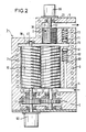
- the primary pump comprises a frame 1 constituting a stator, a suction inlet 4, a discharge outlet 5, a low pressure stage constituted by a dry screw pump 10, and a high pressure stage constituted by a drive pump 20.
- the frame 1 may include cooling channels 2, which allow, by circulation of a liquid (water, oil, ...) to ensure thermal stabilization of the assembly. The heat exchange with the ambient environment takes place by natural or forced convection.
- the pump 10 comprises two conjugated screws 11, 12, mounted respectively on two shafts 13, 14 and synchronized in drive by two pinions 41, 44, the pinion 41 being driven by an electric motor 50.
- the two pinions 41, 44 are installed in an oil box 3 secured to the chassis 1 and sealed against the suction inlet 4 by two seals 48, 49.
- the two shafts 13, 14 rotate in two bearings respectively 42, 43 and 45, 46.
- L 'shaft 13 rotates in another bearing 47 located at the other end, at the connection conduit.
- the pump 20 is a viscous and / or turbulent drive pump, that is to say a pump in which the pumping effect is obtained by friction from a rotor / stator assembly 21 comprising one or more helical grooves variable pitch, whose profile varies between suction and discharge, and rotating at high speed.
- the pump 20 shown is cylindrical but, of course, it can be in the form of a disc or a cone for example.
- the shaft 22 of the pump 20 is mechanically linked to the shaft 14 of the screw 12, so that the motor 50 alone drives the pumps 10 and 20.
- the shaft 22 rotates in a level 23.
- the primary pump comprises two by-passes 60, 70 each equipped with a relief valve 61, 71 to ensure the distribution of the flow in the transient phases.
- the bypass 60 allows the excess gas pumped by the low pressure stage to be recirculated to the suction side 4, and the bypass 70 allows recirculation of excess gas to the discharge side 5.
- valves 61 and 71 can be controlled or automatic, and close under the action of a spring 62, 72 (as shown) or close under the effect of their own weight. But they are, in all cases, closed when there is compatibility between the flow discharged by the low pressure stage and the flow sucked by the high pressure stage.
- the pump 20 is driven separately by an electric motor 80, and, in this case, the shaft 22 of this pump 20 is no longer linked to the shaft 14 of the screw 12, but to the electric motor 80.
- FIG. 2 makes it possible to have a speed of rotation of the pump 20 different from that of the screw pump 10.
- the speed of rotation of the pump 20 can then be easily adapted to the flow rate and to the discharge pressure of the pump 10.
- the volume flow treated is low, as a consequence of the high compression rate obtained in the first stage.
- the overpressure created on the discharge of the low-pressure stage causes the valves 61, 71 to open.
- valve 71 closes, the valve 61 remaining open.
- valve 61 closes and the primary pump operates in steady state.
Landscapes
- Engineering & Computer Science (AREA)
- Mechanical Engineering (AREA)
- General Engineering & Computer Science (AREA)
- Applications Or Details Of Rotary Compressors (AREA)
- Non-Positive Displacement Air Blowers (AREA)
- Compressors, Vaccum Pumps And Other Relevant Systems (AREA)
- Rotary Pumps (AREA)
- Details And Applications Of Rotary Liquid Pumps (AREA)
- Details Of Reciprocating Pumps (AREA)
Priority Applications (1)
| Application Number | Priority Date | Filing Date | Title |
|---|---|---|---|
| AT90110602T ATE86364T1 (de) | 1989-06-05 | 1990-06-05 | Zweistufige trockenprimaerpumpe. |
Applications Claiming Priority (2)
| Application Number | Priority Date | Filing Date | Title |
|---|---|---|---|
| FR8907392A FR2647853A1 (fr) | 1989-06-05 | 1989-06-05 | Pompe primaire seche a deux etages |
| FR8907392 | 1989-06-05 |
Publications (2)
| Publication Number | Publication Date |
|---|---|
| EP0401741A1 true EP0401741A1 (de) | 1990-12-12 |
| EP0401741B1 EP0401741B1 (de) | 1993-03-03 |
Family
ID=9382363
Family Applications (1)
| Application Number | Title | Priority Date | Filing Date |
|---|---|---|---|
| EP90110602A Expired - Lifetime EP0401741B1 (de) | 1989-06-05 | 1990-06-05 | Zweistufige Trockenprimärpumpe |
Country Status (8)
| Country | Link |
|---|---|
| US (1) | US5040949A (de) |
| EP (1) | EP0401741B1 (de) |
| JP (1) | JPH0333492A (de) |
| AT (1) | ATE86364T1 (de) |
| DE (1) | DE69000990T2 (de) |
| ES (1) | ES2039997T3 (de) |
| FR (1) | FR2647853A1 (de) |
| RU (1) | RU1771514C (de) |
Cited By (13)
| Publication number | Priority date | Publication date | Assignee | Title |
|---|---|---|---|---|
| EP0585911A1 (de) * | 1992-09-03 | 1994-03-09 | Matsushita Electric Industrial Co., Ltd. | Zweistufige Trockenprimärpumpe |
| US5445502A (en) * | 1992-01-23 | 1995-08-29 | Matsushita Electric Industrial Co., Ltd. | Vacuum pump having parallel kinetic pump inlet section |
| EP0730093A1 (de) * | 1995-02-28 | 1996-09-04 | Iwata Air Compressor Mfg. Co.,Ltd. | Kontrollsystem für zweistufige Vakuumpumpe |
| EP0798463A3 (de) * | 1996-03-29 | 1998-02-25 | Anest Iwata Corporation | Ölfreie Spiralvakuumpumpe |
| EP0898083A3 (de) * | 1997-08-15 | 1999-07-07 | The BOC Group plc | Vakuum-Pumpsystem |
| EP0857876A3 (de) * | 1997-02-05 | 1999-07-07 | Pfeiffer Vacuum GmbH | Verfahren und Vorrichtung zur Regelung des Saugvermögens von Vakuumpumpen |
| WO2005033028A1 (en) | 2003-10-08 | 2005-04-14 | Draka Fibre Technology B.V. | Method for manufacturing optical fibres and their preforms |
| WO2014001090A1 (de) * | 2012-06-28 | 2014-01-03 | Sterling Industry Consult Gmbh | Verfahren und pumpenanordnung zum evakuieren einer kammer |
| CN103867436A (zh) * | 2008-07-22 | 2014-06-18 | 厄利孔莱博尔德真空技术有限责任公司 | 真空泵、特别是罗茨泵 |
| AU2014407987B2 (en) * | 2014-10-02 | 2019-10-31 | Ateliers Busch Sa | Pumping system for generating a vacuum and method for pumping by means of this pumping system |
| EP3198148B1 (de) * | 2014-09-26 | 2020-02-26 | Ateliers Busch S.A. | Vakuumerzeugendes pumpsystem und pumpverfahren mit diesem pumpsystem |
| IT201800009944A1 (it) | 2018-10-31 | 2020-05-01 | Nova Rotors Srl | "pompa volumetrica" |
| GB2583949A (en) * | 2019-05-15 | 2020-11-18 | Edwards Ltd | A vacuum pump comprising a relief valve and a method of assembly of the relief valve |
Families Citing this family (22)
| Publication number | Priority date | Publication date | Assignee | Title |
|---|---|---|---|---|
| WO1989012751A1 (fr) * | 1988-06-24 | 1989-12-28 | Siemens Aktiengesellschaft | Agregat de pompe a vide a plusieurs etages |
| JPH05272478A (ja) * | 1992-01-31 | 1993-10-19 | Matsushita Electric Ind Co Ltd | 真空ポンプ |
| JPH05209589A (ja) * | 1992-01-31 | 1993-08-20 | Matsushita Electric Ind Co Ltd | 流体回転装置 |
| US5888053A (en) * | 1995-02-10 | 1999-03-30 | Ebara Corporation | Pump having first and second outer casing members |
| DE59909182D1 (de) * | 1999-07-19 | 2004-05-19 | Sterling Fluid Sys Gmbh | Verdrängermaschine für kompressible Medien |
| DE10114585A1 (de) * | 2001-03-24 | 2002-09-26 | Pfeiffer Vacuum Gmbh | Vakuumpumpe |
| DE20110360U1 (de) * | 2001-06-22 | 2002-10-31 | GHH-RAND Schraubenkompressoren GmbH, 46145 Oberhausen | Zweistufiger Schraubenkompressor |
| DE10142567A1 (de) * | 2001-08-30 | 2003-03-20 | Pfeiffer Vacuum Gmbh | Turbomolekularpumpe |
| US6589023B2 (en) | 2001-10-09 | 2003-07-08 | Applied Materials, Inc. | Device and method for reducing vacuum pump energy consumption |
| ITMI20020263A1 (it) * | 2002-02-12 | 2003-08-12 | Alfatech Srl | Pompa per il trasporto di masse fuse di polimeri ed elastomeri |
| JP2003343469A (ja) * | 2002-03-20 | 2003-12-03 | Toyota Industries Corp | 真空ポンプ |
| GB0223769D0 (en) * | 2002-10-14 | 2002-11-20 | Boc Group Plc | A pump |
| GB0416385D0 (en) * | 2004-07-22 | 2004-08-25 | Boc Group Plc | Gas abatement |
| DE102010019402A1 (de) * | 2010-05-04 | 2011-11-10 | Oerlikon Leybold Vacuum Gmbh | Schrauben-Vakuumpumpe |
| US20150078927A1 (en) * | 2013-09-13 | 2015-03-19 | Agilent Technologies, Inc. | Multi-Stage Pump Having Reverse Bypass Circuit |
| DE202014005279U1 (de) | 2014-06-26 | 2015-10-05 | Oerlikon Leybold Vacuum Gmbh | Vakuumpumpen-System |
| DE102016100957A1 (de) * | 2016-01-20 | 2017-07-20 | FRISTAM Pumpen Schaumburg GmbH | Verdrängerpumpe |
| GB201700998D0 (en) * | 2017-01-20 | 2017-03-08 | Edwards Ltd | Multi-stage vacuum booster pump coupling |
| GB201701000D0 (en) | 2017-01-20 | 2017-03-08 | Edwards Ltd | Multi-stage vacuum booster pump coupling |
| WO2021161067A1 (en) | 2020-02-12 | 2021-08-19 | Nova Rotors Srl | Positive displacement pump |
| CN111520321B (zh) * | 2020-05-15 | 2022-09-13 | 大连宏亚泵业有限公司 | 一种机械密封化工泵及其使用方法 |
| GB2606224B (en) | 2021-04-30 | 2024-01-31 | Edwards Ltd | Stator for a vacuum pump |
Citations (4)
| Publication number | Priority date | Publication date | Assignee | Title |
|---|---|---|---|---|
| US3642384A (en) * | 1969-11-19 | 1972-02-15 | Henry Huse | Multistage vacuum pumping system |
| US4090815A (en) * | 1975-12-03 | 1978-05-23 | Aisin Seiki Kabushiki Kaisha | High vacuum pump |
| DE3711143A1 (de) * | 1986-04-14 | 1987-10-15 | Hitachi Ltd | Zweistufige vakuumpumpenvorrichtung |
| EP0256234A2 (de) * | 1986-06-12 | 1988-02-24 | Hitachi, Ltd. | Vakuumerzeugungssystem |
Family Cites Families (3)
| Publication number | Priority date | Publication date | Assignee | Title |
|---|---|---|---|---|
| US2903248A (en) * | 1956-12-10 | 1959-09-08 | Leander H Walker | System of mixing liquiform ingredients |
| GB1517156A (en) * | 1974-06-21 | 1978-07-12 | Svenska Rotor Maskiner Ab | Screw compressor including means for varying the capacity thereof |
| US4781553A (en) * | 1987-07-24 | 1988-11-01 | Kabushiki Kaisha Kobe Seiko Sho | Screw vacuum pump with lubricated bearings and a plurality of shaft sealing means |
-
1989
- 1989-06-05 FR FR8907392A patent/FR2647853A1/fr active Pending
-
1990
- 1990-06-01 US US07/531,726 patent/US5040949A/en not_active Expired - Fee Related
- 1990-06-04 JP JP2146044A patent/JPH0333492A/ja active Pending
- 1990-06-04 RU SU904830083A patent/RU1771514C/ru active
- 1990-06-05 DE DE9090110602T patent/DE69000990T2/de not_active Expired - Fee Related
- 1990-06-05 AT AT90110602T patent/ATE86364T1/de not_active IP Right Cessation
- 1990-06-05 ES ES199090110602T patent/ES2039997T3/es not_active Expired - Lifetime
- 1990-06-05 EP EP90110602A patent/EP0401741B1/de not_active Expired - Lifetime
Patent Citations (4)
| Publication number | Priority date | Publication date | Assignee | Title |
|---|---|---|---|---|
| US3642384A (en) * | 1969-11-19 | 1972-02-15 | Henry Huse | Multistage vacuum pumping system |
| US4090815A (en) * | 1975-12-03 | 1978-05-23 | Aisin Seiki Kabushiki Kaisha | High vacuum pump |
| DE3711143A1 (de) * | 1986-04-14 | 1987-10-15 | Hitachi Ltd | Zweistufige vakuumpumpenvorrichtung |
| EP0256234A2 (de) * | 1986-06-12 | 1988-02-24 | Hitachi, Ltd. | Vakuumerzeugungssystem |
Cited By (21)
| Publication number | Priority date | Publication date | Assignee | Title |
|---|---|---|---|---|
| US5445502A (en) * | 1992-01-23 | 1995-08-29 | Matsushita Electric Industrial Co., Ltd. | Vacuum pump having parallel kinetic pump inlet section |
| US5564907A (en) * | 1992-09-03 | 1996-10-15 | Matsushita Electric Industrial Co., Ltd. | Evacuating apparatus |
| US5709537A (en) * | 1992-09-03 | 1998-01-20 | Matsushita Electric Industrial Co., Ltd. | Evacuating apparatus |
| EP0585911A1 (de) * | 1992-09-03 | 1994-03-09 | Matsushita Electric Industrial Co., Ltd. | Zweistufige Trockenprimärpumpe |
| US5951266A (en) * | 1992-09-03 | 1999-09-14 | Matsushita Electric Industrial Co., Ltd. | Evacuating apparatus having interengaging rotors with threads having a decreasing pitch at the exhaust side |
| US5961297A (en) * | 1995-02-28 | 1999-10-05 | Iwata Air Compressor Mfg. Co., Ltd. | Oil-free two stage scroll vacuum pump and method for controlling the same pump |
| EP0730093A1 (de) * | 1995-02-28 | 1996-09-04 | Iwata Air Compressor Mfg. Co.,Ltd. | Kontrollsystem für zweistufige Vakuumpumpe |
| EP1101943A3 (de) * | 1995-02-28 | 2001-07-25 | Anest Iwata Corporation | Kontrollsystem für zweistufige Vakuumpumpe |
| EP0798463A3 (de) * | 1996-03-29 | 1998-02-25 | Anest Iwata Corporation | Ölfreie Spiralvakuumpumpe |
| US6030181A (en) * | 1997-02-05 | 2000-02-29 | Pfeiffer Vacuum Gmbh | Vacuum apparatus and a method of controlling a suction speed thereof |
| EP0857876A3 (de) * | 1997-02-05 | 1999-07-07 | Pfeiffer Vacuum GmbH | Verfahren und Vorrichtung zur Regelung des Saugvermögens von Vakuumpumpen |
| EP0898083A3 (de) * | 1997-08-15 | 1999-07-07 | The BOC Group plc | Vakuum-Pumpsystem |
| WO2005033028A1 (en) | 2003-10-08 | 2005-04-14 | Draka Fibre Technology B.V. | Method for manufacturing optical fibres and their preforms |
| CN103867436A (zh) * | 2008-07-22 | 2014-06-18 | 厄利孔莱博尔德真空技术有限责任公司 | 真空泵、特别是罗茨泵 |
| WO2014001090A1 (de) * | 2012-06-28 | 2014-01-03 | Sterling Industry Consult Gmbh | Verfahren und pumpenanordnung zum evakuieren einer kammer |
| EP3198148B1 (de) * | 2014-09-26 | 2020-02-26 | Ateliers Busch S.A. | Vakuumerzeugendes pumpsystem und pumpverfahren mit diesem pumpsystem |
| AU2014407987B2 (en) * | 2014-10-02 | 2019-10-31 | Ateliers Busch Sa | Pumping system for generating a vacuum and method for pumping by means of this pumping system |
| EP3201469B1 (de) * | 2014-10-02 | 2020-03-25 | Ateliers Busch S.A. | Pumpsystem zur vakuumerzeugung und verfahren zum pumpen mit diesem pumpsystem |
| IT201800009944A1 (it) | 2018-10-31 | 2020-05-01 | Nova Rotors Srl | "pompa volumetrica" |
| GB2583949A (en) * | 2019-05-15 | 2020-11-18 | Edwards Ltd | A vacuum pump comprising a relief valve and a method of assembly of the relief valve |
| US12031542B2 (en) | 2019-05-15 | 2024-07-09 | Edwards Limited | Vacuum pump comprising a relief valve and a method of assembly of the relief valve |
Also Published As
| Publication number | Publication date |
|---|---|
| ATE86364T1 (de) | 1993-03-15 |
| RU1771514C (ru) | 1992-10-23 |
| DE69000990D1 (de) | 1993-04-08 |
| US5040949A (en) | 1991-08-20 |
| FR2647853A1 (fr) | 1990-12-07 |
| JPH0333492A (ja) | 1991-02-13 |
| DE69000990T2 (de) | 1993-06-09 |
| ES2039997T3 (es) | 1993-10-01 |
| EP0401741B1 (de) | 1993-03-03 |
Similar Documents
| Publication | Publication Date | Title |
|---|---|---|
| EP0401741B1 (de) | Zweistufige Trockenprimärpumpe | |
| BE1014892A5 (fr) | Compresseur a vis sans huile. | |
| EP0002157B1 (de) | Pumpe | |
| EP0000131B1 (de) | Verfahren und Vorrichtung zur Schmierung von Kompressoren | |
| CA2283875A1 (fr) | Machine electrique asynchrone refroidie par liquide | |
| EP1510697B1 (de) | Vakuumpumpe | |
| FR2559848A1 (fr) | Machine a volutes pour comprimer un fluide | |
| EP0368122A1 (de) | Mehrstufige Roots-Vakuumpumpe | |
| FR2675213A1 (fr) | Systeme formant barriere pour l'huile de lubrification des paliers d'un compresseur centrifuge muni de joints d'etancheite a labyrinthe installe dans un environnement confine. | |
| EP0097549B1 (de) | Anordnung um die Abdichtung eines Tauchmotors zu realisieren und sich darauf beziehender Motor | |
| FR2487446A1 (fr) | Groupe de pompage electrique a palette, a joint d'huile, d'encombrement reduit | |
| FR2962173A1 (fr) | Pompe a vide de type seche | |
| FR2565295A1 (fr) | Pompe a vide rotative etanchee dans l'huile | |
| FR2569780A1 (fr) | Procede et dispositif d'etancheite et de pressurisation pour sorties d'arbres de compresseur d'air exempt d'huile | |
| FR3120661A1 (fr) | Compresseur à spirales ayant une pompe à huile centrifuge | |
| EP0143684B1 (de) | Mehrstufiger Serienverdichter | |
| WO2006008232A1 (fr) | Dispositif d'etancheite d'une machine tournante | |
| FR2567208A1 (fr) | Pompe rotative a vide eleve | |
| FR2540190A1 (fr) | Dispositif de graissage a huile sous pression pour pompes a vide rotatives | |
| FR2504989A1 (fr) | Groupe moto-compresseur comportant un circuit de lubrification perfectionne | |
| EP2472126B1 (de) | Verdichter mit Antrieb und verstellbarer, aerodynamischer Geometrie | |
| EP1473462B1 (de) | Patrone zum Zusammenbau eines Verdichters | |
| FR3152168A1 (fr) | Pompe à huile électronique | |
| FR2983539A1 (fr) | Pompe et turbine a palettes | |
| FR2497882A1 (fr) | Perfectionnements apportes aux pompes rotatives |
Legal Events
| Date | Code | Title | Description |
|---|---|---|---|
| PUAI | Public reference made under article 153(3) epc to a published international application that has entered the european phase |
Free format text: ORIGINAL CODE: 0009012 |
|
| AK | Designated contracting states |
Kind code of ref document: A1 Designated state(s): AT BE CH DE DK ES FR GB GR IT LI LU NL SE |
|
| 17P | Request for examination filed |
Effective date: 19910603 |
|
| 17Q | First examination report despatched |
Effective date: 19920522 |
|
| GRAA | (expected) grant |
Free format text: ORIGINAL CODE: 0009210 |
|
| AK | Designated contracting states |
Kind code of ref document: B1 Designated state(s): AT BE CH DE DK ES FR GB GR IT LI LU NL SE |
|
| PG25 | Lapsed in a contracting state [announced via postgrant information from national office to epo] |
Ref country code: SE Effective date: 19930303 Ref country code: GR Free format text: LAPSE BECAUSE OF FAILURE TO SUBMIT A TRANSLATION OF THE DESCRIPTION OR TO PAY THE FEE WITHIN THE PRESCRIBED TIME-LIMIT Effective date: 19930303 Ref country code: DK Effective date: 19930303 Ref country code: AT Effective date: 19930303 |
|
| REF | Corresponds to: |
Ref document number: 86364 Country of ref document: AT Date of ref document: 19930315 Kind code of ref document: T |
|
| GBT | Gb: translation of ep patent filed (gb section 77(6)(a)/1977) |
Effective date: 19930301 |
|
| REF | Corresponds to: |
Ref document number: 69000990 Country of ref document: DE Date of ref document: 19930408 |
|
| PGFP | Annual fee paid to national office [announced via postgrant information from national office to epo] |
Ref country code: ES Payment date: 19930518 Year of fee payment: 4 |
|
| PGFP | Annual fee paid to national office [announced via postgrant information from national office to epo] |
Ref country code: DE Payment date: 19930519 Year of fee payment: 4 Ref country code: CH Payment date: 19930519 Year of fee payment: 4 |
|
| ITF | It: translation for a ep patent filed | ||
| PGFP | Annual fee paid to national office [announced via postgrant information from national office to epo] |
Ref country code: FR Payment date: 19930527 Year of fee payment: 4 |
|
| PG25 | Lapsed in a contracting state [announced via postgrant information from national office to epo] |
Ref country code: LU Free format text: LAPSE BECAUSE OF NON-PAYMENT OF DUE FEES Effective date: 19930630 Ref country code: BE Effective date: 19930630 |
|
| PGFP | Annual fee paid to national office [announced via postgrant information from national office to epo] |
Ref country code: NL Payment date: 19930630 Year of fee payment: 4 |
|
| REG | Reference to a national code |
Ref country code: ES Ref legal event code: FG2A Ref document number: 2039997 Country of ref document: ES Kind code of ref document: T3 |
|
| BERE | Be: lapsed |
Owner name: ALCATEL CIT Effective date: 19930630 |
|
| PLBE | No opposition filed within time limit |
Free format text: ORIGINAL CODE: 0009261 |
|
| STAA | Information on the status of an ep patent application or granted ep patent |
Free format text: STATUS: NO OPPOSITION FILED WITHIN TIME LIMIT |
|
| 26N | No opposition filed | ||
| PG25 | Lapsed in a contracting state [announced via postgrant information from national office to epo] |
Ref country code: GB Effective date: 19940605 |
|
| PG25 | Lapsed in a contracting state [announced via postgrant information from national office to epo] |
Ref country code: ES Free format text: LAPSE BECAUSE OF THE APPLICANT RENOUNCES Effective date: 19940606 |
|
| PG25 | Lapsed in a contracting state [announced via postgrant information from national office to epo] |
Ref country code: LI Effective date: 19940630 Ref country code: CH Effective date: 19940630 |
|
| PG25 | Lapsed in a contracting state [announced via postgrant information from national office to epo] |
Ref country code: NL Effective date: 19950101 |
|
| GBPC | Gb: european patent ceased through non-payment of renewal fee |
Effective date: 19940605 |
|
| NLV4 | Nl: lapsed or anulled due to non-payment of the annual fee | ||
| PG25 | Lapsed in a contracting state [announced via postgrant information from national office to epo] |
Ref country code: FR Effective date: 19950228 |
|
| REG | Reference to a national code |
Ref country code: CH Ref legal event code: PL |
|
| PG25 | Lapsed in a contracting state [announced via postgrant information from national office to epo] |
Ref country code: DE Effective date: 19950301 |
|
| REG | Reference to a national code |
Ref country code: FR Ref legal event code: ST |
|
| REG | Reference to a national code |
Ref country code: ES Ref legal event code: FD2A Effective date: 19991007 |
|
| PG25 | Lapsed in a contracting state [announced via postgrant information from national office to epo] |
Ref country code: IT Free format text: LAPSE BECAUSE OF NON-PAYMENT OF DUE FEES;WARNING: LAPSES OF ITALIAN PATENTS WITH EFFECTIVE DATE BEFORE 2007 MAY HAVE OCCURRED AT ANY TIME BEFORE 2007. THE CORRECT EFFECTIVE DATE MAY BE DIFFERENT FROM THE ONE RECORDED. Effective date: 20050605 |