EP0403115A2 - Automatisches Gerät zum Pressverbinden und Auslegen eines Kabelbaums - Google Patents
Automatisches Gerät zum Pressverbinden und Auslegen eines Kabelbaums Download PDFInfo
- Publication number
- EP0403115A2 EP0403115A2 EP90305931A EP90305931A EP0403115A2 EP 0403115 A2 EP0403115 A2 EP 0403115A2 EP 90305931 A EP90305931 A EP 90305931A EP 90305931 A EP90305931 A EP 90305931A EP 0403115 A2 EP0403115 A2 EP 0403115A2
- Authority
- EP
- European Patent Office
- Prior art keywords
- wire
- wires
- press
- lay
- individually
- Prior art date
- Legal status (The legal status is an assumption and is not a legal conclusion. Google has not performed a legal analysis and makes no representation as to the accuracy of the status listed.)
- Granted
Links
Images


Classifications
-
- H—ELECTRICITY
- H01—ELECTRIC ELEMENTS
- H01R—ELECTRICALLY-CONDUCTIVE CONNECTIONS; STRUCTURAL ASSOCIATIONS OF A PLURALITY OF MUTUALLY-INSULATED ELECTRICAL CONNECTING ELEMENTS; COUPLING DEVICES; CURRENT COLLECTORS
- H01R43/00—Apparatus or processes specially adapted for manufacturing, assembling, maintaining, or repairing of line connectors or current collectors or for joining electric conductors
- H01R43/01—Apparatus or processes specially adapted for manufacturing, assembling, maintaining, or repairing of line connectors or current collectors or for joining electric conductors for connecting unstripped conductors to contact members having insulation cutting edges
-
- H—ELECTRICITY
- H01—ELECTRIC ELEMENTS
- H01R—ELECTRICALLY-CONDUCTIVE CONNECTIONS; STRUCTURAL ASSOCIATIONS OF A PLURALITY OF MUTUALLY-INSULATED ELECTRICAL CONNECTING ELEMENTS; COUPLING DEVICES; CURRENT COLLECTORS
- H01R43/00—Apparatus or processes specially adapted for manufacturing, assembling, maintaining, or repairing of line connectors or current collectors or for joining electric conductors
- H01R43/04—Apparatus or processes specially adapted for manufacturing, assembling, maintaining, or repairing of line connectors or current collectors or for joining electric conductors for forming connections by deformation, e.g. crimping tool
- H01R43/048—Crimping apparatus or processes
- H01R43/052—Crimping apparatus or processes with wire-feeding mechanism
-
- Y—GENERAL TAGGING OF NEW TECHNOLOGICAL DEVELOPMENTS; GENERAL TAGGING OF CROSS-SECTIONAL TECHNOLOGIES SPANNING OVER SEVERAL SECTIONS OF THE IPC; TECHNICAL SUBJECTS COVERED BY FORMER USPC CROSS-REFERENCE ART COLLECTIONS [XRACs] AND DIGESTS
- Y10—TECHNICAL SUBJECTS COVERED BY FORMER USPC
- Y10T—TECHNICAL SUBJECTS COVERED BY FORMER US CLASSIFICATION
- Y10T29/00—Metal working
- Y10T29/53—Means to assemble or disassemble
- Y10T29/5313—Means to assemble electrical device
- Y10T29/532—Conductor
- Y10T29/53243—Multiple, independent conductors
Definitions
- the present invention relates to an automatic wire press-connecting and laying out apparatus for use in making a wire harness in which a group of required wires are press-connected and laid out in a required configuration.
- wire end holders are arranged at predetermined positions on a lay-out board in the actual dimensions of a wire harness to be made, and a wire dispensing head adapted to move in two dimensions along X and Y axes is provided above the lay-out board.
- This wire dispensing head clamps a wire fed from a wire feed portion and distributes it to predetermined wire end holders on the lay-out board, where the ends of the wire are set to be retained, and the wire is then cut, the wire being thereby laid out in a predetermined configuration. This operation is repeated until a required configuration for the wire harness being made is completed.
- individual wires so set in wire end holders are press-connected to terminals in a sequential manner.
- a group of wires required to make a wire harness are automatically press-connected and laid out in a predetermined configuration.
- the main part of the apparatus comprises a connector feed path for forward feeding a pair of connectors, a plurality of groups of work heads disposed along the length of the connector feed path at suitable intervals, and wire feed portions provided for each of the plurality of work head groups.
- a connector feed path for forward feeding a pair of connectors
- a plurality of groups of work heads disposed along the length of the connector feed path at suitable intervals
- wire feed portions provided for each of the plurality of work head groups.
- the former apparatus has the following drawbacks due to the basic construction thereof in which a lay-out board in the actual dimension of a wire harness to be made is employed and in which wires are press-connected and laid out one by one after they have been cut to predetermined dimensions.
- the latter automatic apparatus for forming wires having solderless terminals has the following drawbacks due to the construction thereof in which wires are press-connected to a pair of connectors one by one by work heads arranged linearly.
- An object of the present invention is to provide a novel automatic wire press-connecting and laying out apparatus for a wire harness that can eliminate the above-mentioned drawbacks inherent in the prior art.
- the main portion of the first embodiment comprises: a wire feed portion for feeding out a group of wires that has a mechanism for individually feeding out wires and a mechanism for individually severing wires; separate cassette lay-out boards detachably and horizontally disposed on a frame table in such a manner as to be opposite to each other via a depression and each having a group of connectors detachably disposed at predetermined positions thereon; and a head portion disposed so as to vertically suspend over the cassette lay-out boards and having a transfer means for enabling transfer to a relative position defined by two dimensions along X and Y axes, and a drawing mechanism for individually drawing wires and a wire press-connecting mechanism comprising a plurality of wire press-connecting portions disposed in parallel, these two mechanisms being made to face downwardly.
- a mechanism for individually adjusting the dimension of wires is provided either on the mechanism for individually feeding out wires or on the mechanism for individually drawing wires.
- the ends of a group of wires projecting from the wire feed portion are clamped by the head portion, which distributes the wires to connectors disposed at M end (corresponding to the leading ends of the wires) in a sequential manner with the wires being individually severed to a predetermined dimension.
- the wires so severed are press-connected to the connectors at M end with the intermediate portions thereof being allowed to suspend into the depression so as to be received therein.
- the drawing mechanism draws out the intermediate portions of the respective wires from the depression until the other ends of the wires come to the head portion with the intermediate portions thereof again being allowed to suspend in the depression so as to be received therein, and then the head portion transfers and distributes the wires to connectors at N end (corresponding to the rear ends of the wires), where the wires are press-connected to the connectors at the other end thereof, thereby making it possible to lay out a group of wires in predetermined configuration with both ends thereof being press-connected to the connectors.
- the main portion of the automatic wire press-connecting and laying out apparatus comprises: a wire feed portion for feeding out a group of wires that has a mechanism not only for individually adjusting the dimension of wires but also for individually feeding out wires and a mechanism for individually severing wires; separate cassette lay-out boards detachably and horizontally disposed on a frame table in such a manner as to be opposite to each other via a depression, each having a group of connectors detachably disposed at predetermined positions thereon, and having a transfer means for enabling the transfer thereof in a dimension along the X axis; a head portion disposed so as to vertically suspend over the cassette lay-out boards and having a transfer means for enabling transfer thereof in a dimension along the Y axis and a drawing mechanism for individually drawing wires at the lower portion thereof; and wire press-connecting presses disposed on the frame table at positions adjacent to the outer edges of the cassette lay-out boards disposed opposite to each other.
- the connectors are detachably mounted on a connector fixing jig having a wire holder for temporarily holding a wire.
- the ends of a group of wires projecting from the wire feed portion are clamped by the head portion, which distributes the wires to the wire holders of the connectors disposed at M end (corresponding to the leading ends of the wires) in a sequential manner with the wires being individually severed to a predetermined dimension.
- the wires so severed are press-connected to the connectors at M end by means of the wire press-connecting press with the intermediate portions thereof being allowed to suspend into the depression so as to be received therein.
- the drawing mechanism draws out the intermediate portions of the respective wires from the depression until the other ends of the wires come to the head portion with the intermediate portions thereof again being allowed to suspend in the depression so as to be received therein, and then the head portion transfers and distributes the wires to the wire holders of the connectors at N end (corresponding to the rear ends of the wires) in a sequential manner, where the wires are press-connected to the connectors at the other end thereof by means of the wire press-connecting press, thereby making it possible to lay out a group of wires in predetermined configuration with both ends thereof being press-connected to the connectors.
- a plurality of wires are distributed to the groups of connectors arranged on the separate cassette lay-out boards disposed opposite to each other via the depression every travel of the head portion, and the wires so laid out are then press-connected to the associated connectors with the intermediate portions thereof being allowed to suspend into the depression so as to be received therein.
- the total travelling distance of the head portion can be remarkably reduced to "one-twentieth or thirtieth" of the total length of the wires used, and the number of travelling strokes of the head portion can also be reduced to "one half or third" of the number of wires used, the efficiency of wire press-connecting and layrng out operations for the formation of a wire harness being thereby improved remarkably.
- the press-connecting and laying out of wires are performed on the cassette lay-out boards disposed close to each other. This severs to make the apparatus smaller in size, and the necessity for enormous space for the laying out of wires can be obviated.
- the cassette lay-out boards on which wires have been properly press-connected and laid out only have to be transferred to a wire harness forming conveyor or the like, where the cassette lay-out boards are properly spaced at a predetermined span of wires, and final work such as completing the configurations of the laid out wires, mounting accessory parts and so forth can be carried out, the efficiency of the total wire harness forming operation being thereby improved remarkably.
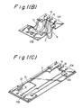
- the main portion of the apparatus comprises a wire feed portion 1 for adjusting the dimension of a group of wires 2 and feeding out the same and a wire press-connecting and laying out portion 3 for press-connecting the group of wires 2 so fed to connectors 16.
- the wire feed portion 1 in turn comprises a wire supply 4 from which various types of wires 2 are drawn out to be supplied in a sequential manner, a mechanism 7 for adjusting the dimension of wires and feeding out the same (hereinafter referred to as "wire dimension adjusting and feeding out mechanism) and a severing mechanism 9. These two mechanisms are provided as a unit on a table 6 of a frame 5.
- the wire press-connecting and laying out portion 3 comprises a pair of separate cassette lay-out boards 10A, 10B disposed horizontally on the table 6 on the frame 5 in such a manner as to be opposite to each other via a depression 15 and each having connectors 16 arranged at predetermined positions thereon, and a head portion 14 vertically suspending from a travelling portal frame 11 provided on the frame 5 in such a manner as to travel over the cassette lay-out boards 10A, 10B in orthogonal dimensions along the X and Y axes, and having a wire drawing mechanism 12 for drawing wires 2 and a wire press-connecting mechanism 13 comprising a plurality of press-connecting portions.
- the head portion 14 clamps the leading ends of a group of wires 12 that protrude from the distal end of the wire feed portion 1 in an laterally parallel fashion and moves to distribute them to the connectors 16 arranged at predetermined positions in a sequential manner, and the intermediate portions of the wires 2 are, as shown in Figs. 1(B), (D), allowed to suspend into the depression 15 so as to be received therein during the movement of the head portion 14.
- the wires 2 are laid out in a predetermined configuration for a wire harness being made, and the wires 2 so laid out are press-connected to the connectors 16 at the ends thereof, thereby making it possible to form a wire harness forming unit A in which the wires having solderless connectors are laid out in a required configuration.
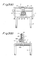
- the wire feed portion 1 has downstream of the wire supply 4 in which wires in various sizes are stored in the form of reels or in buckets the wire dimension adjusting and feeding out mechanism 7 for adjusting the dimension of wires 2 aligned in parallel and individually feeding out the same and the severing mechanism 9 for individually severing the wires 2 the dimension of which has been adjusted accordingly.
- the leading ends of the wires 2 drawn out of the wire supply 4 are caused to protrude from the severing mechanism 9 for transfer to the connectors, and when the leading ends of the wires 2 are fed into the head portion 14, the wire dimension adjusting and feeding out mechanism 7 starts to individually feed out the wires 2 while individually adjusting the dimension thereof, subsequent to which the wires 2 so fed out are individually severed to a predetermined dimension by means of the severing mechanism 9. Afterwards, the wires so severed are fed to the wire press-connecting and laying out portion 3.
- the wire dimension adjusting and feeding out mechanism 7 employed in this embodiment comprises, as shown in Fig. 2(B), a rotatable laterally elongate main roller 18 and sub-rollers 19 disposed above the main roller 18 so as to individually clamp and/or unclamp the wires 2 in cooperation with the former, and in this construction when the wires 2 are individually clamped between the main and respective sub-rollers, the wires 2 are individually fed out while the dimension of the wires 2 are being individually adjusted.
- the severing mechanism 9 has severing blades for individual wires and is mechanically interlocked with the wire dimension adjusting and feeding out mechanism 7 so as to sever the wires 2 when the dimension thereof has been adjusted.
- reference numeral 8 denotes a marking portion for applying a numeral or identification color to wires to be fed out with the dimension thereof being adjusted if such is required
- reference numeral 17 denotes a wire clamp for applying a low tension to wires 2 fed through the wire dimension adjusting and feeding out mechanism 7 with a view to improving the dimension adjusting accuracy of the same mechanism.
- the cassette lay-out boards 10A, 10B of the wire press-connecting and laying out portion 3 are detachably fixed onto the table 6 via the depression 15 that is deep enough to accommodate the longest wire required for a wire harness to be made when it is allowed to suspend thereinto, and the group of connectors 16 to which M ends (the leading ends) of the wires 2 are press-connected are arranged in a required configuration for a wire harness being made mainly on the lay-out board 10A, while the group of connectors 16 to which N ends (the rear ends) of the wires 2 are press-connected are arranged in a required configuration for a wire harness being made mainly on the lay-out board 10B.
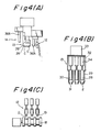
- These groups of connectors are, as shown in Fig.
- connector fixing jigs 24 having a one-touch attaching and/or detaching construction in which when an operation piece 23 is pressed down, a locking pawl 22b is biased forward by the action of a spring, thereby holding the connector 16 so as to be fix in position, while when the locking pawl 22b is allowed to withdraw, the connector 16 is then released.
- the head portion 14 of the wire press-connecting and laying out portion 3 is provided in such a manner as to vertically suspend from a vertical suspending frame 26 mounted on a travelling table 25 adapted to travel in the X axis dimension of the cassette lay-out boards 10A, 10B along an upper beam 11A of the portal frame 11 that is adapted to travel in the Y axis dimension of the cassette lay-out boards 10A, 10B along the sides of the frame 5.
- this vertical suspending frame 26 has a rotation mechanism for allowing itself to rotate through 180° about a vertical suspending shaft 27.
- the head portion 14 is constructed such that it can freely travel in the X and Y axes over the cassette laying boards 10A, 10B, while it can also freely rotate about the axis of the vertical suspending shaft.
- the head portion 14 has the wire press-connecting mechanism 13 and wire drawing mechanism 12, and these mechanisms will be described in detail below.
- the wire press-connecting mechanism 13 comprises a wire press-connecting portion 30 comprising in turn a plurality (three in the drawing) of receiving cases 29 arranged in parallel.
- This receiving case 29 comprises a pair of nail pieces and receives therein a known wire press-connecting blade 28 in such a manner that the blade 28 faces downwardly.
- the receiving case 29 is provided with a slit-like resilient opening 31 at the bottom end thereof.
- a press-connecting blade selection member 34 is provided in a housing 32 above the wire press-connecting portion 30 comprising a plurality of receiving houses 29 arranged in parallel, and an actuator portion 33 is provided above the press-connecting blade selection member 34 to vertically move the same member.
- the wire press-connecting mechanism 13 incorporates a press-connecting blade selection mechanism in which of the press-connecting blades 28 installed only selected one or ones is caused to operate.
- the press-connecting blade selection member 34 is, as shown in Fig. 4(F), caused to selectively operate in the direction as shown by reference arrow B in the housing 32, and a losing notch 35 is formed in the press-connecting blade selection member 34 in such a manner as to extend from the vertically intermediate portion to the bottom portion thereof.
- the press-connecting blades 28 needing to operate are forcibly pressed down so as to operate by the actuator portion 33 via the press-connecting blade selection member 34, while an operation pin 36 provided on the top end of the press-connecting blade 28 that does not need to operate is caused to loosely fit in the losing notch 35 formed in the press-connecting blade selection member 34, the downward force that would be otherwise applied to the relevant press-connecting blade 28 by the actuator portion 33 being thereby lost, and the press-connecting blade 28 is thus prevented from being lowered.
- a sensor C is provided in each receiving case 29 so as to detect whether or not the wire 2 is received therein, as well as the end of the wire 2 so received.
- the opening 31 is caused to resiliently open so as to allow the wire 2 and press-connecting blade 28 to pass therethrough further downwardly, and the wire 2 is press-connected to the connector 16 positioned below the opening 31.
- the press-connecting blade 28 that has been lowered to complete the press-connecting operation is then restored to its original position by the resilient action of a spring.
- the wire drawing mechanism 12 comprises, as shown in Figs. 4(A), (C), the single laterally elongate main roller 18 and the sub-rollers 19 for individually clamping and/or unclamping the wires 2 on the main roller 18 in cooperation of the main roller 18.
- These sub-rollers 19 are adapted to individually clamp the wires 2 needing to be fed out so as to feed out the same toward the side of the press-connecting mechanism 13.
- wire pressing mechanisms 36A and 36B are provided, respectively, between the wire drawing mechanism 12 and press-connecting mechanism 13, and behind the press-connecting mechanism 13.
- the wire pressing mechanism 36A comprises, as shown in Fig. 4(D), a wire holding member 37 and pressing members 38 provided above the wire holding member 37 for individually clamping the wires 2, and this mechanism functions to individually clamp the wires 2 fed out of the wire feed portion 1 and hold them while the head portion 14 travels over the cassette lay-out boards 10A, 10B.
- the other wire pressing mechanism 36B is, as shown in Fig.
- a known peeling machine 40 for press-mounting operations and a terminal press-mounting machine 41 are provided in a corner of the table 6, and terminals may be press-mounted on wires, if such is required.
- the wire press-connecting and laying out apparatus the main portion of which comprises the above-described wire feed portion 1 and wire press-connecting and laying out portion 3 incorporates automatic control circuits each programmed to carry out a series of operations required to form a specific wire harness.
- an automatic control circuit storing a particular program designed to form a wire harness of a particular construction controls a series of required operations; wires 2 needed are selectively fed out to the head portion 14 while the dimension thereof being adjusted, the head portion 14 then selects connectors to which the wires are press-connected and distributes them to the connectors so selected, and the wires are press-connected to the connectors.
- the automatic control circuits also control operations of the individual constituent elements, cooperations therebetween, operations selectively performed by particular constituent elements and so forth during a series of required operations.
- a wire harness is automatically formed by the action of the automatic control circuits as will be described below.
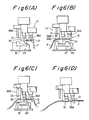
- the wire drawing mechanisms 12 of the head portion 14 selectively draws wires 2 needed, and the wires 2 so selected are, as shown in Fig. 4(A), clamped by means of the wire clamping mechanism 36A, and the leading ends of the wires are thus transferred to the head portion 14.
- the wires 2 are fed out by means of the wire dimension adjusting and feeding out mechanism 7.
- the wire drawing mechanism 12 is, as shown in Fig. 6(A), caused to operate so as to insert the leading end of the selected wire 2 into the wire press-connecting portion 30, subsequent to which the press-connecting blade 28 is selectively lowered so that only the wire needing to be press-connected are press-connected to the connector 16′ at M end thereof.
- the head portion 14 then moves to another connector 16, to which the remaining clamped wire is press-connected at M end thereof in the same manner.
- the head portion 14 When the wires clamped by the head portion 14 have been press-connected to the predetermined connectors at M ends thereof, the head portion 14 lays out the clamped wires in required configurations while feeding them oat rearwardly with the intermediate portions thereof being allowed to suspend into the depression 15 so as to be received therein, and the head portion 14 then moves toward the cassette lay-out board 10B.
- the wires clamped by the head portion 14 are fed out by means of the wire dimension adjusting and feeding out mechanism 7 while the dimension thereof being adjusted by the same mechanism 7, and when the wires are fed out to a predetermined dimension, they are individually severed by the severing mechanism 9.
- the head portion 14 moves and stops over a predetermined connector 16 ⁇ on which a wire press-connecting operation is to be first carried out with N ends of the wires being held thereon by means of the wire pressing mechanism 36A, and the wire pressing mechanism 37B is actuated so as to selectively fix only the wire to be press-connected to the connector 16 ⁇ to the upper end of the connector fixing jig 24 for the stabilization of the posture thereof, subsequent to which as soon as the wire pressing mechanism 36A is released, the wire press-connecting portion is caused to selectively press-connect only the wire needed to the connector 16 ⁇ at N end thereof.
- the head portion 14 then moves to another connector to which the remaining clamped wire is to be press-connected at N end thereof, and the relevant wire is then press-connected to the connector accordingly.
- the wire harness forming unit A completed as described above is then placed on a forming conveyor 20, and the cassette lay-out boards 10A, 10B are spaced at the normal span thereof, the wire harness forming unit A being thereby laid out properly on the conveyor as shown in Fig. 1(C).
- the bundle of wires are then set on lay-out branching jigs 21 provided on the conveyor 20 so that a required lay-out configuration for a wire harness being made is completed, and bundling taping, grommets and other accessory parts are mounted on the wires.
- the connectors 16 are dismounted from the cassette lay-out boards 10A, 10B, thus making it possible to form a desired wire harness.
- the head portion 14 moves to a predetermined intermediate connector 16 after the press-connecting of wires has been completed at M ends thereof, as shown in Fig. 6(C), the relevant intermediate portion of the wire is press-connected to the intermediate connector 16 by the wire press-connecting portion 30.
- the head portion 14 is then caused to rotate so as to adjust the direction of the wire, and the wire is properly press-connected to the predetermined connector 16.
- the head portion 14 moves to the peeling machine 40 and press-mounting machine 41, and the terminal is then press-mounted to the end of the wire held by the wire pressing mechanism 36A and protruding from the head portion 14.
- the solderless terminal so press-mounted on the wire is inserted into a predetermined connector during the wire harness forming operation that is carried out on the forming conveyor 20.
- the wires are transferred from the wire feed portion 1 to the head portion 14 having the wire press-connecting mechanism comprising a plurality of wire press-connecting portions, and the head portion 14 holding the wires sequentially moves to the connectors provided on the cassette lay-out boards 10A, 10B that are disposed within a short distance in such a manner as to be opposite to each other via the depression 15, and the wires are laid out in a predetermined configuration with the intermediate portions of the wires being allowed to suspend into the depression 15 so as to be received therein.
- the wires so distributed are press-connected to the connectors in a sequential fashion, thereby making it possible to automatically form a wire harness forming unit A in which the wires having the press-connected connectors are laid out in a required configuration for a wire harness being made.
- the whole travelling distance and the number of travelling strokes of the head portion 14 can remarkably be reduced, respectively.
- cassette lay-out boards 10A, 10B are disposed with in a short distance in such a manner as to be opposite to each other via the depression 15, and this construction requires less space to form a wire harness compared with the prior art lay-out boards which are formed into an actual dimensions of a wire harness to be made, thereby making it possible to make the size of the apparatus smaller.
- the dimension adjusting mechanism of the wire dimension adjusting and feeding out mechanism 7 of the wire feed portion 1 is transferred to the wire drawing mechanism 12 of the head portion 14 so that the dimension of the wires may be adjusted while they are being drawn during the transfer of the head portion 14, and the severing mechanism 9 of the wire feed portion 1 may be mechanically interlocked with the adjustment of the dimension of the wires performed in the head portion 14.
- the direction in which the connectors are disposed on the cassette lay-out boards 10A, 10B may be restricted in such a manner that the direction in which the wires are press-connected to the connectors 16 becomes parallel to the Y axis along which the head portion 14 is transferred, and the rotation mechanism of the head portion 14 may be omitted.
- a transfer mechanism for enabling transfer in the X axis dimension may be provided on the table 6, and alternately the X axis dimension transfer mechanism of the head portion 14 may be omitted.
- the relative position between the head portion 14 and the two dimensions of the cassette lay-out boards 10A, 10B may be freely taken by allowing the table 6 to travel along the X axis, while the head portion 14 is allowed to travel along the Y axis.
- the wire clamping function of the wire drawing mechanism 12 may be utilized instead of the wire pressing mechanism 36A, and thus the latter may be omitted.
- a cassette lay-out board 10C on which intermediate connectors 16 to which the intermediate portions of the wires are press-connected are arranged may be provided between the cassette lay-out boards 10A, 10B, and depressions 15 may be provided, respectively, between the cassette lay-out boards 10A and 10C and between the cassette lay-out boards 10C and 10B.
- the construction in which the three cassette lay-out boards are used may be adopted.
- non-symmetrical cassette lay-out boards 10A, 10B may be utilized.
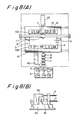
- the wire press-connecting mechanism 13 of the head portion 14 utilized in the first embodiment is omitted.
- independent press-connecting presses 43 are provided at positions adjacent to the outer edges of the cassette lay-out boards 10A, 10B, and a transfer mechanism for enabling transfer along the X axis is provided on the table 6.
- the head portion 14 is provided at the laterally central position of the travelling portal frame 11 adapted to travel along the sides of the frame 5 in such a manner as to vertically suspend therefrom, and the direction in which it is disposed is fixed.
- a slide mechanism for enabling transfer along the Y axis is provided on the press-connecting press 43 so as to allow the press to move towards and/or away from the cassette lay-out boards 10A, 10B, and a wire holder 42 is provided on the connector fixing jig 24.
- This wire holder 42 may be formed, for instance as shown in Fig. 8(B), such that the wire is temporarily held in the slot portion formed therein.
- the wire feed portion 1, cassette lay-out boards 10A, 10B, and the depression 15 are the same as those utilized in the first embodiment, and the head portion 14 is also provided with the same wire drawing mechanism 12 and wire pressing mechanism 36A as those utilized in the first embodiment.
- the wires 2 fed from the wire feed portion 1 are sequentially distributed to the wire holders 42 on the connectors 16 arranged on the cassette lay-out boards 10A, 10B so as to be temporarily held in position, and the wires are thus laid out.
- the connectors 16 to which the wires are so held are then sequentially brought in front of the press-connecting press 43 by moving the table 6 along the X axis, and the wires 2 temporarily held on the wire holders 42 are then sequentially press-connected to the connectors 16 by the press-connecting press 43 when it is moved forward.
- the wire press-connecting and laying out apparatus which is shown in Fig. 8, has also the connectors 16 on the cassette lay-out boards 10A, 10B that are disposed within a short distance in such a manner as to be opposite to each other via the depression 15, the cassette lay-out boards and the wire dispensing head portion 14 that can freely take any relative position along the two dimensions.
- a function similar to that of the first embodiment shown in Fig. 1 can also be expected.
- the efficiency of the press-connecting and laying out wires can remarkably be improved, and moreover, it is possible to obviate the necessity of enormous space for the laying out of wires. Consequently, the present invention is advantageous in that the productivity of wire harnesses can remarkably be improved.
Landscapes
- Engineering & Computer Science (AREA)
- Manufacturing & Machinery (AREA)
- Supply And Installment Of Electrical Components (AREA)
- Manufacturing Of Electrical Connectors (AREA)
Applications Claiming Priority (2)
| Application Number | Priority Date | Filing Date | Title |
|---|---|---|---|
| JP148797/89 | 1989-06-12 | ||
| JP1148797A JPH06105565B2 (ja) | 1989-06-12 | 1989-06-12 | ワイヤハーネス用自動圧接布線装置 |
Publications (3)
| Publication Number | Publication Date |
|---|---|
| EP0403115A2 true EP0403115A2 (de) | 1990-12-19 |
| EP0403115A3 EP0403115A3 (de) | 1992-05-06 |
| EP0403115B1 EP0403115B1 (de) | 1996-05-15 |
Family
ID=15460923
Family Applications (1)
| Application Number | Title | Priority Date | Filing Date |
|---|---|---|---|
| EP90305931A Expired - Lifetime EP0403115B1 (de) | 1989-06-12 | 1990-05-31 | Automatisches Gerät zum Pressverbinden und Auslegen eines Kabelbaums |
Country Status (4)
| Country | Link |
|---|---|
| US (1) | US5052449A (de) |
| EP (1) | EP0403115B1 (de) |
| JP (1) | JPH06105565B2 (de) |
| DE (1) | DE69026977T2 (de) |
Cited By (8)
| Publication number | Priority date | Publication date | Assignee | Title |
|---|---|---|---|---|
| EP0496294A3 (en) * | 1991-01-17 | 1993-01-27 | Japan Aviation Electronics Industry, Limited | Cable guide block for use in a cable connection processing apparatus |
| EP0862251A1 (de) * | 1997-02-26 | 1998-09-02 | Harness System Technologies Research, Ltd. | Verfahren zur Herstellung eines Kabelbaumes für den Automobilbau |
| US5913553A (en) * | 1996-05-20 | 1999-06-22 | Yazaki Corporation | Method of manufacturing a wiring harness |
| EP0967122A3 (de) * | 1998-06-22 | 2002-04-10 | Sumitomo Wiring Systems, Ltd. | Verfahren zur elektrischen Kabellängenfeststellung, verwendbar in einer Kabelbaumherstellung, und Kabelbaumherstellungsverfahren |
| WO2003019580A1 (en) * | 2001-08-27 | 2003-03-06 | Yazaki Corporation | Method and device for manufacturing wire harness |
| CN102291978A (zh) * | 2011-08-26 | 2011-12-21 | 东莞市新泽谷机械有限公司 | 可调节送线规格的送跳线机构 |
| CN106448934A (zh) * | 2013-10-04 | 2017-02-22 | 矢崎总业株式会社 | 线束生产系统和线束生产方法 |
| CN107123482A (zh) * | 2017-06-20 | 2017-09-01 | 上海应用技术大学 | 一种全自动线束缠绕机 |
Families Citing this family (19)
| Publication number | Priority date | Publication date | Assignee | Title |
|---|---|---|---|---|
| CH684374A5 (de) * | 1992-11-17 | 1994-08-31 | Komax Holding Ag | Kabelzuführungs- und -wechseleinrichtung für eine Kabelverarbeitungsmaschine. |
| JP2902938B2 (ja) * | 1994-03-29 | 1999-06-07 | ヒロセ電機株式会社 | 自動結線装置用ケーブル端部屈曲成形装置 |
| US6230404B1 (en) * | 1996-05-09 | 2001-05-15 | Sumitomo Wiring Systems, Ltd. | Method and apparatus for producing a wiring harness |
| JPH10203271A (ja) * | 1997-01-28 | 1998-08-04 | Harness Sogo Gijutsu Kenkyusho:Kk | 自動車用ワイヤーハーネスの製造 |
| JP3889846B2 (ja) * | 1997-03-19 | 2007-03-07 | 矢崎総業株式会社 | 圧接布線装置及びハーネス製造方法 |
| JP3358154B2 (ja) * | 1997-08-27 | 2002-12-16 | 矢崎総業株式会社 | ワイヤハーネス、その製造方法および装置 |
| US6306781B1 (en) | 1999-07-21 | 2001-10-23 | Senior Investments Ag | Expansion joint patch apparatus |
| JP2005285343A (ja) * | 2004-03-26 | 2005-10-13 | Jst Mfg Co Ltd | 端子付き電線製造装置および端子付き電線の製造方法 |
| US7454829B2 (en) * | 2004-10-22 | 2008-11-25 | Bruce Anderson | Cable sorting threader and labeling tool |
| JP5993685B2 (ja) * | 2012-09-26 | 2016-09-14 | 矢崎総業株式会社 | 電線圧接装置 |
| JP5950305B2 (ja) * | 2012-09-26 | 2016-07-13 | 矢崎総業株式会社 | 電線圧接装置 |
| CN103441403B (zh) * | 2013-09-03 | 2015-07-29 | 傅国钢 | 一种排插座电源线束绕线机及绕制电源线束的方法 |
| CN103682944A (zh) * | 2014-01-10 | 2014-03-26 | 江苏华凯线束有限公司 | 一种线束端子压接机整形机构 |
| CN104942183B (zh) * | 2015-06-15 | 2017-05-24 | 中山市亚泰机械实业有限公司 | 送线机构的前置检测校直装置 |
| CN106025757B (zh) * | 2016-07-04 | 2018-05-25 | 鹤壁海昌专用设备有限公司 | 一种带自动换线和自动换模装置的全自动下线压接机 |
| US10374400B2 (en) * | 2017-09-18 | 2019-08-06 | John D Tillotson, JR. | Discrete wire harness single or dual operator work center |
| DE102019206243A1 (de) * | 2019-04-30 | 2020-11-05 | Leoni Bordnetz-Systeme Gmbh | Ablängstation sowie Verfahren zum automatischen Ablängen von Leitungselementen |
| CN112951515B (zh) * | 2021-02-03 | 2022-05-20 | 百事联电子(厦门)有限公司 | 一种汽车线束智能加工工艺 |
| JP7351866B2 (ja) | 2021-03-17 | 2023-09-27 | 矢崎総業株式会社 | ワイヤハーネスの配索治具および部品製造システム |
Family Cites Families (16)
| Publication number | Priority date | Publication date | Assignee | Title |
|---|---|---|---|---|
| US3693228A (en) | 1970-11-12 | 1972-09-26 | Gerber Scientific Instr Co | Machine for assembling wire harness |
| US3844462A (en) * | 1970-12-31 | 1974-10-29 | Hughes Aircraft Co | Dispensing head for strand material |
| US3804130A (en) * | 1970-12-31 | 1974-04-16 | Hughes Aircraft Co | Form board for receiving and removably retaining strand material |
| JPS5022270A (de) * | 1973-06-30 | 1975-03-10 | ||
| JPS5422822B2 (de) * | 1973-06-30 | 1979-08-09 | ||
| US3907007A (en) * | 1974-01-23 | 1975-09-23 | Western Electric Co | Apparatus and method for forming wires on a wire-receiving member |
| US3930524A (en) * | 1974-10-17 | 1976-01-06 | Tarbox John W | Harness making apparatus |
| US4033386A (en) * | 1975-12-18 | 1977-07-05 | Western Electric Company, Inc. | Wiring head with resiliently locked and resettable guide tube mounting assembly |
| DE2702188C2 (de) * | 1977-01-20 | 1985-03-14 | Grote & Hartmann Gmbh & Co Kg, 5600 Wuppertal | Verfahren und Vorrichtung zum Herstellen von Teilkabelbäumen |
| CA1176436A (en) * | 1980-10-07 | 1984-10-23 | Vladimiro Teagno | Method and apparatus for making modular electrical harnesses including wire holding head |
| US4380117A (en) | 1981-05-26 | 1983-04-19 | Amp Incorporated | Electrical harness fabricating apparatus |
| JPS59178000A (ja) * | 1983-03-28 | 1984-10-08 | 三菱電機株式会社 | 自動配線装置 |
| GB8429512D0 (en) * | 1984-11-22 | 1985-01-03 | Molex Inc | Assembling electrical harnesses |
| US4593452A (en) | 1985-02-26 | 1986-06-10 | Amp Incorporated | Robotic harness maker |
| JPH0793060B2 (ja) * | 1986-08-29 | 1995-10-09 | 株式会社日立製作所 | 自動布線装置 |
| JPH01102813A (ja) * | 1987-10-15 | 1989-04-20 | Niigata Eng Co Ltd | 配線束の端部処理方法及び装置 |
-
1989
- 1989-06-12 JP JP1148797A patent/JPH06105565B2/ja not_active Expired - Fee Related
-
1990
- 1990-05-25 US US07/528,940 patent/US5052449A/en not_active Expired - Lifetime
- 1990-05-31 DE DE69026977T patent/DE69026977T2/de not_active Expired - Fee Related
- 1990-05-31 EP EP90305931A patent/EP0403115B1/de not_active Expired - Lifetime
Cited By (16)
| Publication number | Priority date | Publication date | Assignee | Title |
|---|---|---|---|---|
| EP0496294A3 (en) * | 1991-01-17 | 1993-01-27 | Japan Aviation Electronics Industry, Limited | Cable guide block for use in a cable connection processing apparatus |
| US6722021B2 (en) | 1996-05-20 | 2004-04-20 | Yazaki Corporation | Crimping apparatus |
| US5913553A (en) * | 1996-05-20 | 1999-06-22 | Yazaki Corporation | Method of manufacturing a wiring harness |
| US6269538B1 (en) | 1996-05-20 | 2001-08-07 | Yazaki Corporation | Press fitting apparatus for manufacturing a wiring harness |
| US6662444B2 (en) | 1996-05-20 | 2003-12-16 | Yazaki Corporation | Method and apparatus of manufacturing wiring harness |
| US5970609A (en) * | 1997-02-26 | 1999-10-26 | Harness System Technologies Research, Ltd. | Method of manufacturing wire harness for automobile use |
| EP0862251A1 (de) * | 1997-02-26 | 1998-09-02 | Harness System Technologies Research, Ltd. | Verfahren zur Herstellung eines Kabelbaumes für den Automobilbau |
| EP0967122A3 (de) * | 1998-06-22 | 2002-04-10 | Sumitomo Wiring Systems, Ltd. | Verfahren zur elektrischen Kabellängenfeststellung, verwendbar in einer Kabelbaumherstellung, und Kabelbaumherstellungsverfahren |
| WO2003019580A1 (en) * | 2001-08-27 | 2003-03-06 | Yazaki Corporation | Method and device for manufacturing wire harness |
| US7296334B2 (en) | 2001-08-27 | 2007-11-20 | Yazaki Corporation | Method and device for manufacturing wire harness |
| CN102291978B (zh) * | 2011-08-26 | 2014-07-30 | 东莞市新泽谷机械制造股份有限公司 | 可调节送线规格的送跳线机构 |
| CN102291978A (zh) * | 2011-08-26 | 2011-12-21 | 东莞市新泽谷机械有限公司 | 可调节送线规格的送跳线机构 |
| CN106448934A (zh) * | 2013-10-04 | 2017-02-22 | 矢崎总业株式会社 | 线束生产系统和线束生产方法 |
| CN106448934B (zh) * | 2013-10-04 | 2018-12-21 | 矢崎总业株式会社 | 线束生产系统和线束生产方法 |
| CN107123482A (zh) * | 2017-06-20 | 2017-09-01 | 上海应用技术大学 | 一种全自动线束缠绕机 |
| CN107123482B (zh) * | 2017-06-20 | 2023-01-20 | 上海应用技术大学 | 一种全自动线束缠绕机 |
Also Published As
| Publication number | Publication date |
|---|---|
| DE69026977D1 (de) | 1996-06-20 |
| US5052449A (en) | 1991-10-01 |
| DE69026977T2 (de) | 1996-10-02 |
| EP0403115B1 (de) | 1996-05-15 |
| JPH0315118A (ja) | 1991-01-23 |
| EP0403115A3 (de) | 1992-05-06 |
| JPH06105565B2 (ja) | 1994-12-21 |
Similar Documents
| Publication | Publication Date | Title |
|---|---|---|
| EP0403115B1 (de) | Automatisches Gerät zum Pressverbinden und Auslegen eines Kabelbaums | |
| US8528199B2 (en) | Manufacturing apparatus for wiring harnesses and a manufacturing method for wiring harnesses | |
| US4087908A (en) | Connector harness assembly machine | |
| US4360962A (en) | Wire harness | |
| US4593452A (en) | Robotic harness maker | |
| US4126935A (en) | Method and apparatus for manufacturing wiring harnesses | |
| EP0778587A2 (de) | Elektrischer Flachdraht für Drahtbündel und dessen Herstellungsverfahren und -apparat | |
| EP0657355A1 (de) | Verfahren und Vorrichtung zum Binden eines Kabelbaums mittels Klebeband | |
| US4290179A (en) | Cable harness assembly machine | |
| GB2024052A (en) | Method and apparatus for wiring loom production | |
| EP0001891B1 (de) | Vorrichtung zum Einführen von Drähten in elektrische Anschlussklemmen | |
| US4403407A (en) | Multiple wire terminal applying | |
| JPS60119014A (ja) | ハーネス製造方法および装置 | |
| KR0164428B1 (ko) | 리본 케이블에의 커넥터 설치기 | |
| US5123808A (en) | Apparatus for loading connectors into connector applicators | |
| JPH04229910A (ja) | リード線製造装置及びそれに使用するワイヤ把持装置 | |
| JPH0745352A (ja) | 異種端子付テープおよび端子圧着機 | |
| US5492155A (en) | Wire laying-out apparatus | |
| JP3013657B2 (ja) | 電線受渡し機構及びこれを含んだ電線受渡し装置 | |
| US5472129A (en) | Template for guiding a plurality of wires | |
| US5727305A (en) | Programmable pin feeder | |
| JPS60175315A (ja) | リボンケ−ブル用自動圧接機 | |
| JPH06103841A (ja) | 布線板 | |
| JPH0118550B2 (de) | ||
| JPH104294A (ja) | 電子部品挿入装置 |
Legal Events
| Date | Code | Title | Description |
|---|---|---|---|
| PUAI | Public reference made under article 153(3) epc to a published international application that has entered the european phase |
Free format text: ORIGINAL CODE: 0009012 |
|
| AK | Designated contracting states |
Kind code of ref document: A2 Designated state(s): DE FR GB |
|
| RAP1 | Party data changed (applicant data changed or rights of an application transferred) |
Owner name: SUMITOMO WIRING SYSTEMS, LTD. |
|
| PUAL | Search report despatched |
Free format text: ORIGINAL CODE: 0009013 |
|
| AK | Designated contracting states |
Kind code of ref document: A3 Designated state(s): DE FR GB |
|
| 17P | Request for examination filed |
Effective date: 19921029 |
|
| 17Q | First examination report despatched |
Effective date: 19940321 |
|
| GRAH | Despatch of communication of intention to grant a patent |
Free format text: ORIGINAL CODE: EPIDOS IGRA |
|
| GRAA | (expected) grant |
Free format text: ORIGINAL CODE: 0009210 |
|
| AK | Designated contracting states |
Kind code of ref document: B1 Designated state(s): DE FR GB |
|
| REF | Corresponds to: |
Ref document number: 69026977 Country of ref document: DE Date of ref document: 19960620 |
|
| ET | Fr: translation filed | ||
| PLBE | No opposition filed within time limit |
Free format text: ORIGINAL CODE: 0009261 |
|
| STAA | Information on the status of an ep patent application or granted ep patent |
Free format text: STATUS: NO OPPOSITION FILED WITHIN TIME LIMIT |
|
| 26N | No opposition filed | ||
| PGFP | Annual fee paid to national office [announced via postgrant information from national office to epo] |
Ref country code: FR Payment date: 20010518 Year of fee payment: 12 |
|
| PGFP | Annual fee paid to national office [announced via postgrant information from national office to epo] |
Ref country code: GB Payment date: 20010530 Year of fee payment: 12 |
|
| REG | Reference to a national code |
Ref country code: GB Ref legal event code: IF02 |
|
| PG25 | Lapsed in a contracting state [announced via postgrant information from national office to epo] |
Ref country code: GB Free format text: LAPSE BECAUSE OF NON-PAYMENT OF DUE FEES Effective date: 20020531 |
|
| PGFP | Annual fee paid to national office [announced via postgrant information from national office to epo] |
Ref country code: DE Payment date: 20020610 Year of fee payment: 13 |
|
| GBPC | Gb: european patent ceased through non-payment of renewal fee |
Effective date: 20020531 |
|
| PG25 | Lapsed in a contracting state [announced via postgrant information from national office to epo] |
Ref country code: FR Free format text: LAPSE BECAUSE OF NON-PAYMENT OF DUE FEES Effective date: 20030131 |
|
| REG | Reference to a national code |
Ref country code: FR Ref legal event code: ST |
|
| PG25 | Lapsed in a contracting state [announced via postgrant information from national office to epo] |
Ref country code: DE Free format text: LAPSE BECAUSE OF NON-PAYMENT OF DUE FEES Effective date: 20031202 |