EP0403761B1 - Connecteur optique - Google Patents
Connecteur optique Download PDFInfo
- Publication number
- EP0403761B1 EP0403761B1 EP90107714A EP90107714A EP0403761B1 EP 0403761 B1 EP0403761 B1 EP 0403761B1 EP 90107714 A EP90107714 A EP 90107714A EP 90107714 A EP90107714 A EP 90107714A EP 0403761 B1 EP0403761 B1 EP 0403761B1
- Authority
- EP
- European Patent Office
- Prior art keywords
- guide
- grooves
- guide pin
- optical connector
- optical
- Prior art date
- Legal status (The legal status is an assumption and is not a legal conclusion. Google has not performed a legal analysis and makes no representation as to the accuracy of the status listed.)
- Expired - Lifetime
Links
- 230000003287 optical effect Effects 0.000 title claims description 46
- 239000013307 optical fiber Substances 0.000 claims description 42
- 230000008878 coupling Effects 0.000 claims description 25
- 238000010168 coupling process Methods 0.000 claims description 25
- 238000005859 coupling reaction Methods 0.000 claims description 25
- 239000000758 substrate Substances 0.000 claims description 11
- 238000003780 insertion Methods 0.000 claims description 4
- 230000037431 insertion Effects 0.000 claims description 4
- 238000000605 extraction Methods 0.000 claims description 3
- 238000003825 pressing Methods 0.000 claims description 3
- 239000000835 fiber Substances 0.000 description 5
- 239000003822 epoxy resin Substances 0.000 description 3
- 238000000227 grinding Methods 0.000 description 3
- 229920000647 polyepoxide Polymers 0.000 description 3
- XUIMIQQOPSSXEZ-UHFFFAOYSA-N Silicon Chemical compound [Si] XUIMIQQOPSSXEZ-UHFFFAOYSA-N 0.000 description 2
- 238000005304 joining Methods 0.000 description 2
- 230000000717 retained effect Effects 0.000 description 2
- 239000010935 stainless steel Substances 0.000 description 2
- 229910001220 stainless steel Inorganic materials 0.000 description 2
- 238000001721 transfer moulding Methods 0.000 description 2
- 229910000881 Cu alloy Inorganic materials 0.000 description 1
- 229910000639 Spring steel Inorganic materials 0.000 description 1
- 239000000853 adhesive Substances 0.000 description 1
- 230000001070 adhesive effect Effects 0.000 description 1
- DMFGNRRURHSENX-UHFFFAOYSA-N beryllium copper Chemical compound [Be].[Cu] DMFGNRRURHSENX-UHFFFAOYSA-N 0.000 description 1
- 239000011247 coating layer Substances 0.000 description 1
- 230000000994 depressogenic effect Effects 0.000 description 1
- 238000002474 experimental method Methods 0.000 description 1
- 230000001771 impaired effect Effects 0.000 description 1
- 238000003754 machining Methods 0.000 description 1
- 238000004519 manufacturing process Methods 0.000 description 1
- 238000000034 method Methods 0.000 description 1
- 229910021421 monocrystalline silicon Inorganic materials 0.000 description 1
- 239000010409 thin film Substances 0.000 description 1
Images

Classifications
-
- G—PHYSICS
- G02—OPTICS
- G02B—OPTICAL ELEMENTS, SYSTEMS OR APPARATUS
- G02B6/00—Light guides; Structural details of arrangements comprising light guides and other optical elements, e.g. couplings
- G02B6/24—Coupling light guides
-
- G—PHYSICS
- G02—OPTICS
- G02B—OPTICAL ELEMENTS, SYSTEMS OR APPARATUS
- G02B6/00—Light guides; Structural details of arrangements comprising light guides and other optical elements, e.g. couplings
- G02B6/24—Coupling light guides
- G02B6/36—Mechanical coupling means
- G02B6/38—Mechanical coupling means having fibre to fibre mating means
- G02B6/3807—Dismountable connectors, i.e. comprising plugs
- G02B6/3833—Details of mounting fibres in ferrules; Assembly methods; Manufacture
- G02B6/3834—Means for centering or aligning the light guide within the ferrule
- G02B6/3838—Means for centering or aligning the light guide within the ferrule using grooves for light guides
- G02B6/3839—Means for centering or aligning the light guide within the ferrule using grooves for light guides for a plurality of light guides
-
- G—PHYSICS
- G02—OPTICS
- G02B—OPTICAL ELEMENTS, SYSTEMS OR APPARATUS
- G02B6/00—Light guides; Structural details of arrangements comprising light guides and other optical elements, e.g. couplings
- G02B6/24—Coupling light guides
- G02B6/36—Mechanical coupling means
- G02B6/38—Mechanical coupling means having fibre to fibre mating means
- G02B6/3807—Dismountable connectors, i.e. comprising plugs
- G02B6/3873—Connectors using guide surfaces for aligning ferrule ends, e.g. tubes, sleeves, V-grooves, rods, pins, balls
- G02B6/3885—Multicore or multichannel optical connectors, i.e. one single ferrule containing more than one fibre, e.g. ribbon type
-
- G—PHYSICS
- G02—OPTICS
- G02B—OPTICAL ELEMENTS, SYSTEMS OR APPARATUS
- G02B6/00—Light guides; Structural details of arrangements comprising light guides and other optical elements, e.g. couplings
- G02B6/24—Coupling light guides
- G02B6/36—Mechanical coupling means
- G02B6/38—Mechanical coupling means having fibre to fibre mating means
- G02B6/3807—Dismountable connectors, i.e. comprising plugs
- G02B6/389—Dismountable connectors, i.e. comprising plugs characterised by the method of fastening connecting plugs and sockets, e.g. screw- or nut-lock, snap-in, bayonet type
-
- G—PHYSICS
- G02—OPTICS
- G02B—OPTICAL ELEMENTS, SYSTEMS OR APPARATUS
- G02B6/00—Light guides; Structural details of arrangements comprising light guides and other optical elements, e.g. couplings
- G02B6/24—Coupling light guides
- G02B6/36—Mechanical coupling means
- G02B6/38—Mechanical coupling means having fibre to fibre mating means
- G02B6/3807—Dismountable connectors, i.e. comprising plugs
- G02B6/3833—Details of mounting fibres in ferrules; Assembly methods; Manufacture
- G02B6/3855—Details of mounting fibres in ferrules; Assembly methods; Manufacture characterised by the method of anchoring or fixing the fibre within the ferrule
- G02B6/3858—Clamping, i.e. with only elastic deformation
-
- G—PHYSICS
- G02—OPTICS
- G02B—OPTICAL ELEMENTS, SYSTEMS OR APPARATUS
- G02B6/00—Light guides; Structural details of arrangements comprising light guides and other optical elements, e.g. couplings
- G02B6/24—Coupling light guides
- G02B6/36—Mechanical coupling means
- G02B6/38—Mechanical coupling means having fibre to fibre mating means
- G02B6/3807—Dismountable connectors, i.e. comprising plugs
- G02B6/3873—Connectors using guide surfaces for aligning ferrule ends, e.g. tubes, sleeves, V-grooves, rods, pins, balls
Definitions
- the present invention relates to an optical connector for use in optical communications to connect optical fibers in proper alignment with each other in such a way that they can be disconnected as required.
- Figs. 1A and 1B show a conventional optical connector fabricated by the transfer molding of an epoxy resin.
- Fig. 1A is a perspective view of the connector before the connection, and
- Fig. 1B shows an end face of the connector.
- An optical connector ferrule 20 molded from epoxy resin has optical fiber guide holes 21 and two guide pin holes 22 formed in its interior.
- the guide holes 21 are used to fix, in proper alignment, coated optical fibers A after the coating layer of an end portion is stripped to expose the individual fibers. In order to connect these optical fibers, they are inserted into the guide holes 21 and fixed in proper axial alignment. Thereafter, two guide pins 23 are inserted the respective pin holes 22.
- optical fibers cannot be connected with high precision of positioning.
- the optical fibers to be connected are single-mode optical fibers having a core diameter of only about 9-10 ⁇ m or dispersion-shifted optical fibers having a core diameter less than the single-mode optical diameter, it is very difficult to accomplish low-loss and consistent connection of the optical fibers.
- EP-A-271721 discloses an optical connector which recognises and solves such a problem by providing clamper means which tolerates a certain dimensional variation in the guide pin.
- This optical connector comprises a grooved substrate provided in its top surface with optical fiber guide grooves and guide pin grooves which is overlaid with a flat plate which covers only the optical fiber guide grooves in such a way that the guide pin grooves are exposed.
- Two such optical connectors are coupled together by the clamper means having a resilient compressive force and being attached from the rear end of the optical fiber guide member while guide pins are inserted from the front end.
- the guide pins are secured in the guide pin grooves by the resilient compressive force of the clamper.
- the present invention achieves its object by Providing an optical connector for connecting optical fibers in proper axial alignment with each other, comprising the features set out in claim 1.
- the guide pins are pressed down in two stages such that the guide pins inserted are retained temporarily by a comparatively weak force by means of the vertically movable member which allows manually handling them with ease.
- the coupling clips are externally applied to the plugs so that the guide pins are further pressed downward and gripped more effectively to realise a firm and reliable joining of optical fibers.
- Fig. 2 is a cross section showing a specific example of the optical connector of the present invention.
- the reference numeral 1 designates an optical fiber guide member which comprises a grooved substrate 11 and a cover plate 12.
- the substrate 11 has optical fiber guide grooves 13 and guide pin grooves 14 cut in its top surface, and the cover plate 12 is joined to the substrate 11 so that the fiber guide grooves 13 are covered by the plate 12 but at least part of the guide pin grooves 14 is exposed.
- a pressing member 3 movable in the vertical direction of the guide pin grooves 14 is provided above the guide grooves so that the guide pins 2 which are positioned on the guide pin grooves are pressed downward when optical fibers are connected by the optical connector.
- coupling clips 4 are mounted so that the movable member 3 will be pressed downward to enhance the force of elastic pressure being exerted on the guide pins 2.
- guide pins 2 are elastically pressed downward by the vertically movable member 3.
- the greater force by which the guide pins are depressed the more consistently the guide pins are held in contact with the guide pin grooves 14.
- the increase in the force of depression will lead to an increase in frictional resistance that develops when guide pins 2 are inserted into or extracted from the optical connector and, as a result, the efficiency of inserting the guide pins 2 into the gap between the movable member 3 and the guide pin grooves 14 in the substrate 1 or extracting them from said gap will be impaired.
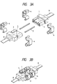
- Figs. 3A and 3B show an embodiment of the present invention in which it is applied to a multi-fiber optical connector capable of jointing twelve single-mode fibers in one operation.
- Fig. 3A is a perspective view of the optical connector before it joins optical fibers
- Fig. 3B is a perspective view showing two plugs of connector coupled together.
- the optical fiber guide member 1 consists of two silicon chips, one being grooved and the other being flat.
- the silicon chips are made of single-crystal silicon which is suitable for grinding machining because of high grinding ratio. Twelve optical fiber guide grooves and two guide pin grooves are formed on the top surface of the grooved chip by grinding, and the flat chip is bonded to the fiber guide grooves by means of a thin-film adhesive.
- the optical fiber guide member 1 is partly surrounded by a press-worked stainless steel which is bonded to all sides except the top surface of the guide member in such a way that the movable member 3, which is movable in the vertical direction of the guide pin grooves and is a part of the stainless steel member, is positioned slightly above the guide pin grooves.
- the vertically movable member 3 will deform by about 50 ⁇ m to exert a pressing force of about 9.80665N (1 kgf) on the guide pins 2.
- a resistance less than about 1,96N (0.2 kgf) will develop upon insertion or extraction of the guide pins 2 but this is not so great as to preclude manual insertion or extraction of guide pins 2 without using any special tools.
- the two-stage pressure application is performed as already stated above and an additional pressure is applied by means of coupling clip 4 which are mounted after the two plugs of optical connector are coupled.
- Each plug is equipped with two clips 4 in such a way that the force of pressure exerted on the associated guide pins is enhanced.
- a total of four coupling clips 4 are used to couple the two plugs.
- the clips 4 are advantageously made of a beryllium-copper alloy or a SUS spring steel.
- each of the coupling clips 4 is designed to have a respective grip force of 29.4N (3 kgf).
- the coupling clips 4 are mounted or dismounted by a special tool.
- the force required for the guide pin to be inserted or extracted increased to about 7.8 - 9.8 N (0.8 - 1 kgf) per each when the connector was equipped with the coupling clips 4. and this guaranteed that the optical connector was capable of withstanding an applied tensile force ranging from about 14.7 to 19.6 N (1.5 to 2 kgf).
- optical fibers could be connected or disconnected in a consistent way and the variations in coupling loss were less than 0.05 in terms of standard deviations ( ⁇ ).
- the optical connector of the present invention is characterized in that a member capable of moving in the vertical direction of guide pin grooves that presses guide pins downward is provided above the guide pin grooves.
- a member capable of moving in the vertical direction of guide pin grooves that presses guide pins downward is provided above the guide pin grooves.
- the optical connector of the present invention is further characterized in that the guide pins are pressed downward in two stages.
- the guide pins inserted are retained temporarily by a comparatively weak force by means of the vertically movable member, so they can be handled manually with great ease.
- the coupling clips are externally applied to the plugs so that the guide pins are further pressed downward and gripped more effectively to realize a firm and reliable joining of optical fibers.
Landscapes
- Physics & Mathematics (AREA)
- General Physics & Mathematics (AREA)
- Optics & Photonics (AREA)
- Mechanical Coupling Of Light Guides (AREA)
Claims (4)
- Connecteur optique destiné à connecter des fibres optiques en alignement axial correct les unes avec les autres, ledit connecteur optique comprenant:- un élément guide (1) pour des fibres optiques, qui comprend un substrat rainuré (11) et une plaque de couverture (12), ledit substrat comportant des rainures de guidage (13) pour les fibres optiques et des rainures (14) pour des tiges-guide, découpées dans une surface supérieure dudit substrat, et ladite plaque de couverture étant réunie audit substrat d'une manière telle qu'elle couvre les rainures de guidage des fibres optiques mais laisse exposée au moins une partie des rainures des tiges-guide ; et- un élément de serrage mobile (3) positionné au-dessus desdites rainures (14) des tiges-guide d'une manière telle que lorsque lesdites tiges-guide (2) sont introduites dans lesdites rainures (14) pour les tiges-guide afin d'aligner deux desdits connecteurs et de réunir les fibres optiques, ledit élément mobile presse élastiquement vers le bas uniquement sur les tiges-guide (2) à l'intérieur desdites rainures (14) pour les tiges-guide,caractérisé en ce qu'il comprend en outre des pinces d'accouplement (4) agencées de manière à saisir l'élément mobile (3) afin de renforcer la force de pressage dirigée vers le bas exercée sur la tige-guide associée par l'élément mobile (3), et en ce que les pinces d'accouplement (4) sont destinées à être montées après l'introduction des tiges-guide (2).
- Connecteur optique selon la revendication 1, dans lequel la force de pression par laquelle les tiges-guide (2) sont pressées vers le bas au moyen dudit élément verticalement mobile (3) en l'absence des pinces d'accouplement n'est pas supérieure à 4,9N (0,5 kgf) par rapport à la force nécessaire pour l'introduction ou l'extraction desdites tiges-guides.
- Connecteur optique selon la revendication 1, dans lequel lesdites tiges-guide (2) sont maintenues en contact avec deux surfaces intérieures des rainures (14) pour les tiges-guide.
- Connecteur optique selon la revendication 1, dans lequel lesdites rainures de guidage (13) des fibres optiques et lesdites rainures (14) pour les tiges-guide sur ledit substrat sont des rainures en forme de V.
Applications Claiming Priority (2)
| Application Number | Priority Date | Filing Date | Title |
|---|---|---|---|
| JP161676/89 | 1989-06-23 | ||
| JP1161676A JP2590266B2 (ja) | 1989-06-23 | 1989-06-23 | 光コネクタ |
Publications (2)
| Publication Number | Publication Date |
|---|---|
| EP0403761A1 EP0403761A1 (fr) | 1990-12-27 |
| EP0403761B1 true EP0403761B1 (fr) | 1994-10-05 |
Family
ID=15739725
Family Applications (1)
| Application Number | Title | Priority Date | Filing Date |
|---|---|---|---|
| EP90107714A Expired - Lifetime EP0403761B1 (fr) | 1989-06-23 | 1990-04-24 | Connecteur optique |
Country Status (7)
| Country | Link |
|---|---|
| US (1) | US4983012A (fr) |
| EP (1) | EP0403761B1 (fr) |
| JP (1) | JP2590266B2 (fr) |
| KR (1) | KR910001413A (fr) |
| AU (1) | AU621731B2 (fr) |
| CA (1) | CA2015190C (fr) |
| DE (1) | DE69013068T2 (fr) |
Families Citing this family (25)
| Publication number | Priority date | Publication date | Assignee | Title |
|---|---|---|---|---|
| IT1240310B (it) * | 1989-07-24 | 1993-12-07 | Pirelli Cavi Spa | Gruppo di connessione separabile per fibre ottiche riunite a nastro e relativo metodo di realizzazione. |
| US5082346A (en) * | 1990-06-28 | 1992-01-21 | At&T Bell Laboratories | Field-assemblable multifiber optical connector |
| US5379360A (en) * | 1992-06-03 | 1995-01-03 | Ngk Insulators, Ltd. | Optical fiber connector and method of manufacturing the same |
| JP2851796B2 (ja) * | 1994-07-28 | 1999-01-27 | 日本碍子株式会社 | 光ファイバアレイの基板への固定方法 |
| JP3853866B2 (ja) * | 1995-02-21 | 2006-12-06 | 日本碍子株式会社 | 光ファイバー固定用基板 |
| JPH09120014A (ja) * | 1995-08-24 | 1997-05-06 | Ngk Insulators Ltd | 光ファイバアレイ |
| US5737463A (en) * | 1995-12-22 | 1998-04-07 | Weiss; Roger E. | Massive parallel optical interconnect system |
| US6045270A (en) | 1995-12-22 | 2000-04-04 | Methode Electronics, Inc. | Massive parallel optical interconnect system |
| US6318902B1 (en) | 1996-03-12 | 2001-11-20 | 3M Innovative Properties Company | Optical connector assembly using partial large diameter alignment features |
| US6805493B2 (en) | 1996-03-12 | 2004-10-19 | 3M Innovative Properties Company | Optical connector assembly using partial large diameter alignment features |
| JP3602339B2 (ja) * | 1997-06-16 | 2004-12-15 | 株式会社フジクラ | 光コネクタ |
| KR20010030946A (ko) * | 1998-08-07 | 2001-04-16 | 오카야마 노리오 | 광 커넥터용 페룰, 그 성형용 금형, 광 커넥터용 페룰의제조 방법 및, 광 커넥터용 페룰의 검사 방법 |
| US6628865B2 (en) | 2000-12-15 | 2003-09-30 | Intel Corporation | Alignment of optical fibers to an etched array waveguide |
| US6886989B2 (en) * | 2000-12-15 | 2005-05-03 | Intel Corporation | Alignment of fiber optic bundle to array waveguide using pins |
| US6707970B2 (en) | 2000-12-15 | 2004-03-16 | Intel Corporation | Alignment of fiber optic bundle to array waveguide using an epoxy |
| US6695488B2 (en) | 2001-07-19 | 2004-02-24 | Cinch Connectors, Inc. | Tool and method for forming a multi fiber ferrule |
| JP2008505362A (ja) * | 2004-06-30 | 2008-02-21 | イクスポーネント フォトニクス,インコーポレイティド | ファイバ結合光学機器のパッケージ化 |
| US7543993B2 (en) | 2006-03-03 | 2009-06-09 | Hoya Corporation Usa | Fiber-coupled optical device mounted on a circuit board |
| AU2012376220B2 (en) * | 2012-04-05 | 2017-02-09 | Cudoquanta Florida, Inc. | Ferrule for optical fiber connector having a compliant structure for clamping alignment pins |
| DE102012112683A1 (de) * | 2012-12-19 | 2014-06-26 | Reichle & De-Massari Ag | Optische Leiterplatte |
| JP6278627B2 (ja) * | 2013-07-18 | 2018-02-14 | 富士通コンポーネント株式会社 | 光モジュール |
| JP6502028B2 (ja) * | 2014-06-24 | 2019-04-17 | 富士通コンポーネント株式会社 | 光コネクタの製造方法及び光コネクタ |
| KR101672459B1 (ko) | 2014-10-24 | 2016-11-08 | 김희문 | 앞바퀴 굴림 자전거 |
| JP6694206B2 (ja) * | 2016-04-12 | 2020-05-13 | 日東電工株式会社 | 光コネクタ部材およびそれを用いた光コネクタキット、並びにそれによって得られる光配線 |
| US20230333329A1 (en) * | 2020-09-11 | 2023-10-19 | Nippon Telegraph And Telephone Corporation | Multi-fiber optical connector and manufacturing method thereof |
Family Cites Families (19)
| Publication number | Priority date | Publication date | Assignee | Title |
|---|---|---|---|---|
| US3864018A (en) * | 1973-10-18 | 1975-02-04 | Bell Telephone Labor Inc | Method and means for splicing arrays of optical fibers |
| JPS5473061A (en) * | 1977-11-21 | 1979-06-12 | Nec Corp | Connector for optical fibers |
| FR2415314A1 (fr) * | 1978-01-19 | 1979-08-17 | Souriau & Cie | Module de connexion pour conducteurs optiques monobrins et connecteur muni de tels modules |
| JPS5570810A (en) * | 1978-11-21 | 1980-05-28 | Nec Corp | Molded connector for optical communication |
| JPS55101904A (en) * | 1979-01-31 | 1980-08-04 | Nippon Telegr & Teleph Corp <Ntt> | Connector for multicore optical fiber cable |
| DE3408783A1 (de) * | 1983-08-03 | 1985-02-14 | Siemens AG, 1000 Berlin und 8000 München | Verbindungselement fuer lichtwellenleiter und verfahren zur herstellung |
| EP0160663A1 (fr) * | 1983-10-27 | 1985-11-13 | AT&T Corp. | Connexions de fibres optiques |
| JPS6161111A (ja) * | 1984-09-01 | 1986-03-28 | Sumitomo Electric Ind Ltd | 多心光コネクタ |
| JPS6283709A (ja) * | 1985-10-09 | 1987-04-17 | Hiroshi Tottori | 光ケ−ブル用端子 |
| DE3608019A1 (de) * | 1986-03-11 | 1987-09-17 | Siemens Ag | Verbindungselement fuer mehrere lichtwellenleiter |
| DE3608053A1 (de) * | 1986-03-11 | 1987-09-17 | Siemens Ag | Verbindungselement fuer mehrere in einer reihe angeordnete lichtwellenleiter |
| CA1283569C (fr) * | 1986-03-14 | 1991-04-30 | Toshiaki Kakii | Raccord et dispositif pour epissure de fibres optiques |
| JPS62269108A (ja) * | 1986-05-16 | 1987-11-21 | Sumitomo Electric Ind Ltd | 多心光コネクタフエル−ル及びその製造方法 |
| JPS6356619A (ja) * | 1986-08-27 | 1988-03-11 | Sumitomo Electric Ind Ltd | 多心光コネクタの結合方法及びそれに用いる多心光コネクタフエル−ル |
| EP0264108B1 (fr) * | 1986-10-16 | 1992-03-25 | Siemens Aktiengesellschaft | Elément de connexion pour guides d'ondes optiques |
| US4830456A (en) * | 1986-11-15 | 1989-05-16 | Sumitomo Electric Industries, Ltd. | Optical connector and process for producing the same |
| US4778243A (en) * | 1986-12-08 | 1988-10-18 | Siemens Aktiengesellschaft | Connector element for a light waveguide |
| US4921325A (en) * | 1987-12-25 | 1990-05-01 | Mitsubishi Cable Industries, Ltd. | Connector for optical fiber ribbon and a method of attaching the same |
| US4818058B1 (en) * | 1988-03-03 | 1995-04-25 | Bell Telephone Labor Inc | Optical connector. |
-
1989
- 1989-06-23 JP JP1161676A patent/JP2590266B2/ja not_active Expired - Fee Related
-
1990
- 1990-04-23 AU AU53817/90A patent/AU621731B2/en not_active Ceased
- 1990-04-23 CA CA002015190A patent/CA2015190C/fr not_active Expired - Fee Related
- 1990-04-23 US US07/512,415 patent/US4983012A/en not_active Expired - Lifetime
- 1990-04-24 EP EP90107714A patent/EP0403761B1/fr not_active Expired - Lifetime
- 1990-04-24 DE DE69013068T patent/DE69013068T2/de not_active Expired - Fee Related
- 1990-06-19 KR KR1019900009011A patent/KR910001413A/ko not_active Withdrawn
Non-Patent Citations (1)
| Title |
|---|
| PATENT ABSTRACTS OF JAPAN, vol 6, no 116 (P-125)(994), 29 June 1982 & JP A 57044113 * |
Also Published As
| Publication number | Publication date |
|---|---|
| CA2015190A1 (fr) | 1990-12-23 |
| EP0403761A1 (fr) | 1990-12-27 |
| KR910001413A (ko) | 1991-01-30 |
| JP2590266B2 (ja) | 1997-03-12 |
| CA2015190C (fr) | 1993-09-21 |
| US4983012A (en) | 1991-01-08 |
| DE69013068T2 (de) | 1995-01-26 |
| JPH0327009A (ja) | 1991-02-05 |
| AU621731B2 (en) | 1992-03-19 |
| AU5381790A (en) | 1991-01-03 |
| DE69013068D1 (de) | 1994-11-10 |
Similar Documents
| Publication | Publication Date | Title |
|---|---|---|
| EP0403761B1 (fr) | Connecteur optique | |
| EP0271721B1 (fr) | Connecteur optique et son procédé de fabrication | |
| US6293708B1 (en) | Optical connector, and using method and tool thereof | |
| US4478485A (en) | Connector for coupling at least one optical fiber to a further optical element | |
| US7118284B2 (en) | Optical connector plug, optical connector adapter and optical connector | |
| US5862289A (en) | Adhesiveless fiber optic connector, and an apparatus and method for terminating a fiber optic cable to an adhesiveless fiber optic connector | |
| US5093881A (en) | Connector for interconnecting optical fiber cable ribbons | |
| US5452386A (en) | Fiber optics connector and a method of making the same | |
| JPH10170756A (ja) | 光コネクタおよびその取付方法 | |
| JP2005157129A (ja) | 光コネクタ | |
| US4323300A (en) | Optical fibre connectors | |
| JPH1172659A (ja) | 光学的な多重コネクタ | |
| JP2000284146A (ja) | 積層可能なマルチファイバフェルールの組立方法 | |
| EP1596231B1 (fr) | Procede de connexion de support de transmission optique et structure de connexion optique | |
| US6846111B2 (en) | Method of processing optical fiber end portion | |
| CA2537354A1 (fr) | Connecteur optique | |
| GB2374157A (en) | Mounting an optical fibre using a retaining channel | |
| JP2000338371A (ja) | 光ファイバ用コネクタ | |
| JPH0583883B2 (fr) | ||
| JPS63261309A (ja) | 光導波体用コネクタ | |
| JP2569329B2 (ja) | 光コネクタ | |
| JPH0573204B2 (fr) | ||
| JP3236995B2 (ja) | 光ファイバ接続装置 | |
| JP3318264B2 (ja) | 光コネクタ | |
| JPH0486609A (ja) | 光コネクタ |
Legal Events
| Date | Code | Title | Description |
|---|---|---|---|
| PUAI | Public reference made under article 153(3) epc to a published international application that has entered the european phase |
Free format text: ORIGINAL CODE: 0009012 |
|
| AK | Designated contracting states |
Kind code of ref document: A1 Designated state(s): DE FR GB IT NL SE |
|
| 17P | Request for examination filed |
Effective date: 19901220 |
|
| 17Q | First examination report despatched |
Effective date: 19930507 |
|
| GRAA | (expected) grant |
Free format text: ORIGINAL CODE: 0009210 |
|
| AK | Designated contracting states |
Kind code of ref document: B1 Designated state(s): DE FR GB IT NL SE |
|
| REF | Corresponds to: |
Ref document number: 69013068 Country of ref document: DE Date of ref document: 19941110 |
|
| ITF | It: translation for a ep patent filed | ||
| ET | Fr: translation filed | ||
| EAL | Se: european patent in force in sweden |
Ref document number: 90107714.9 |
|
| PLBE | No opposition filed within time limit |
Free format text: ORIGINAL CODE: 0009261 |
|
| STAA | Information on the status of an ep patent application or granted ep patent |
Free format text: STATUS: NO OPPOSITION FILED WITHIN TIME LIMIT |
|
| 26N | No opposition filed | ||
| PGFP | Annual fee paid to national office [announced via postgrant information from national office to epo] |
Ref country code: FR Payment date: 19970409 Year of fee payment: 8 |
|
| PGFP | Annual fee paid to national office [announced via postgrant information from national office to epo] |
Ref country code: GB Payment date: 19970415 Year of fee payment: 8 |
|
| PGFP | Annual fee paid to national office [announced via postgrant information from national office to epo] |
Ref country code: SE Payment date: 19970418 Year of fee payment: 8 |
|
| PGFP | Annual fee paid to national office [announced via postgrant information from national office to epo] |
Ref country code: NL Payment date: 19970428 Year of fee payment: 8 |
|
| PGFP | Annual fee paid to national office [announced via postgrant information from national office to epo] |
Ref country code: DE Payment date: 19970505 Year of fee payment: 8 |
|
| PG25 | Lapsed in a contracting state [announced via postgrant information from national office to epo] |
Ref country code: GB Free format text: LAPSE BECAUSE OF NON-PAYMENT OF DUE FEES Effective date: 19980424 |
|
| PG25 | Lapsed in a contracting state [announced via postgrant information from national office to epo] |
Ref country code: SE Free format text: LAPSE BECAUSE OF NON-PAYMENT OF DUE FEES Effective date: 19980425 |
|
| PG25 | Lapsed in a contracting state [announced via postgrant information from national office to epo] |
Ref country code: FR Free format text: THE PATENT HAS BEEN ANNULLED BY A DECISION OF A NATIONAL AUTHORITY Effective date: 19980430 |
|
| PG25 | Lapsed in a contracting state [announced via postgrant information from national office to epo] |
Ref country code: NL Free format text: LAPSE BECAUSE OF NON-PAYMENT OF DUE FEES Effective date: 19981101 |
|
| GBPC | Gb: european patent ceased through non-payment of renewal fee |
Effective date: 19980424 |
|
| NLV4 | Nl: lapsed or anulled due to non-payment of the annual fee |
Effective date: 19981101 |
|
| EUG | Se: european patent has lapsed |
Ref document number: 90107714.9 |
|
| PG25 | Lapsed in a contracting state [announced via postgrant information from national office to epo] |
Ref country code: DE Free format text: LAPSE BECAUSE OF NON-PAYMENT OF DUE FEES Effective date: 19990202 |
|
| REG | Reference to a national code |
Ref country code: FR Ref legal event code: ST |
|
| PG25 | Lapsed in a contracting state [announced via postgrant information from national office to epo] |
Ref country code: IT Free format text: LAPSE BECAUSE OF NON-PAYMENT OF DUE FEES;WARNING: LAPSES OF ITALIAN PATENTS WITH EFFECTIVE DATE BEFORE 2007 MAY HAVE OCCURRED AT ANY TIME BEFORE 2007. THE CORRECT EFFECTIVE DATE MAY BE DIFFERENT FROM THE ONE RECORDED. Effective date: 20050424 |