EP0405614A2 - Système de direction des roues arrières d'un véhicule - Google Patents
Système de direction des roues arrières d'un véhicule Download PDFInfo
- Publication number
- EP0405614A2 EP0405614A2 EP90112620A EP90112620A EP0405614A2 EP 0405614 A2 EP0405614 A2 EP 0405614A2 EP 90112620 A EP90112620 A EP 90112620A EP 90112620 A EP90112620 A EP 90112620A EP 0405614 A2 EP0405614 A2 EP 0405614A2
- Authority
- EP
- European Patent Office
- Prior art keywords
- rear wheel
- wheel steering
- passage
- power cylinder
- steering system
- Prior art date
- Legal status (The legal status is an assumption and is not a legal conclusion. Google has not performed a legal analysis and makes no representation as to the accuracy of the status listed.)
- Ceased
Links
- 230000007246 mechanism Effects 0.000 claims abstract description 46
- 239000007788 liquid Substances 0.000 claims abstract description 30
- 230000004044 response Effects 0.000 claims abstract description 4
- 230000007935 neutral effect Effects 0.000 claims description 6
- 230000009471 action Effects 0.000 abstract description 8
- 230000002093 peripheral effect Effects 0.000 description 9
- 238000006073 displacement reaction Methods 0.000 description 4
- 238000010586 diagram Methods 0.000 description 2
- 230000004048 modification Effects 0.000 description 2
- 238000012986 modification Methods 0.000 description 2
- 230000001133 acceleration Effects 0.000 description 1
- 230000001771 impaired effect Effects 0.000 description 1
- 230000001502 supplementing effect Effects 0.000 description 1
Images



Classifications
-
- B—PERFORMING OPERATIONS; TRANSPORTING
- B62—LAND VEHICLES FOR TRAVELLING OTHERWISE THAN ON RAILS
- B62D—MOTOR VEHICLES; TRAILERS
- B62D7/00—Steering linkage; Stub axles or their mountings
- B62D7/06—Steering linkage; Stub axles or their mountings for individually-pivoted wheels, e.g. on king-pins
- B62D7/14—Steering linkage; Stub axles or their mountings for individually-pivoted wheels, e.g. on king-pins the pivotal axes being situated in more than one plane transverse to the longitudinal centre line of the vehicle, e.g. all-wheel steering
- B62D7/15—Steering linkage; Stub axles or their mountings for individually-pivoted wheels, e.g. on king-pins the pivotal axes being situated in more than one plane transverse to the longitudinal centre line of the vehicle, e.g. all-wheel steering characterised by means varying the ratio between the steering angles of the steered wheels
- B62D7/1518—Steering linkage; Stub axles or their mountings for individually-pivoted wheels, e.g. on king-pins the pivotal axes being situated in more than one plane transverse to the longitudinal centre line of the vehicle, e.g. all-wheel steering characterised by means varying the ratio between the steering angles of the steered wheels comprising a mechanical interconnecting system between the steering control means of the different axles
- B62D7/1536—Steering linkage; Stub axles or their mountings for individually-pivoted wheels, e.g. on king-pins the pivotal axes being situated in more than one plane transverse to the longitudinal centre line of the vehicle, e.g. all-wheel steering characterised by means varying the ratio between the steering angles of the steered wheels comprising a mechanical interconnecting system between the steering control means of the different axles provided with hydraulic assistance
-
- B—PERFORMING OPERATIONS; TRANSPORTING
- B62—LAND VEHICLES FOR TRAVELLING OTHERWISE THAN ON RAILS
- B62D—MOTOR VEHICLES; TRAILERS
- B62D7/00—Steering linkage; Stub axles or their mountings
- B62D7/06—Steering linkage; Stub axles or their mountings for individually-pivoted wheels, e.g. on king-pins
- B62D7/14—Steering linkage; Stub axles or their mountings for individually-pivoted wheels, e.g. on king-pins the pivotal axes being situated in more than one plane transverse to the longitudinal centre line of the vehicle, e.g. all-wheel steering
- B62D7/15—Steering linkage; Stub axles or their mountings for individually-pivoted wheels, e.g. on king-pins the pivotal axes being situated in more than one plane transverse to the longitudinal centre line of the vehicle, e.g. all-wheel steering characterised by means varying the ratio between the steering angles of the steered wheels
- B62D7/1518—Steering linkage; Stub axles or their mountings for individually-pivoted wheels, e.g. on king-pins the pivotal axes being situated in more than one plane transverse to the longitudinal centre line of the vehicle, e.g. all-wheel steering characterised by means varying the ratio between the steering angles of the steered wheels comprising a mechanical interconnecting system between the steering control means of the different axles
Definitions
- the present invention relates to a rear wheel steering system for a vehicle for steering the rear wheels together with the front wheels.
- Japanese Patent Unexamined Publication (kokai) No. 152,977/1987 discloses a rear wheel steering system for a vehicle, in which its rear wheel steering mechanism is provided with a power steering unit which has a power cylinder for generating a power for steering the rear wheels in response to a liquid pressure, the power cylinder being connected through a high pressure passage to a pump as a source of generating the liquid pressure as well as through a low pressure passage to a reservoir tank.
- this system is provided with a spring for biasing the rear wheels toward the neutral position as well as with a fail valve which communicates the liquid chambers in the power cylinder with each other for placing the power cylinder in its neutral position.
- the pump for the power steering unit is always driven during operation of the engine, so that this pump tries to keep supplying the liquid pressure to the power cylinder even at the time of a fail.
- a relief passage is separately disposed so as to communicate the high pressure passage with the low pressure passage and that a fail valve is disposed on the relief passage, the fail valve being made open at the fail time.
- the power cylinder is allowed to gradually release the liquid pressure as slow as possible in order to prevent the rear wheels from steering to the neutral position.
- the relief passage is provided with a restrictor.
- the position of this restrictor may suffer from the disadvantage that the liquid pressure would not be released from the pump to the low pressure passage to a sufficient extent due to the action of the restrictor, thereby suppressing a release of the liquid pressure from the power cylinder.
- the object of the present invention is to provide a rear wheel steering system for a vehicle adapted to gradually release a liquid pressure from the power cylinder through the high pressure passage without exerting any influence upon the liquid pressure to be withdrawn from the pump.
- the present invention consists of a rear wheel steering system for a vehicle, comprising a power cylinder disposed to a rear wheel steering mechanism for generating a power of steering rear wheels in response to a liquid pressure; wherein the power cylinder is connected through a high pressure passage to a pump as a source of generating the liquid pressure and through a low pressure passage to a reservoir tank; the high pressure passage is connected to the low pressure passage through a relief passage on the pump side and a relief passage on the power cylinder side, the relief passage on the pump side being disposed in parallel to the relief passage on the power cylinder side; a passage shifting means for opening each of the relief passage on the pump side and the relief passage on the power cylinder side during operation, which otherwise are closed, and for dividing the high pressure passage between the relief passage on the pump side and the relief passage on the power cylinder side; and the relief passage on the power cylinder side is provided with a restrictor.
- This arrangement enables the liquid pressure to be released to the low pressure passage and eventually to the reservoir tank by dividing the high pressure passage into the high pressure passages on the pump side and on the power cylinder side due to operation of a shift valve.
- the action of the restrictor disposed to the relief passage on the power cylinder side allows the liquid pressure to be gradually released from the power cylinder, thereby prevent the rear wheels from rapidly steering.
- the liquid pressure discharged from the pump is rapidly released into the low pressure passage through the relief passage on the pump side without interference with the restrictor.
- the present invention ensures a gradual release of the liquid pressure from the power cylinder at the time of a fail or the like, while the liquid pressure is reease d without delay from the pump.
- a right-hand front wheel 1R and a left-hand front wheel 1L are associated with a front wheel steering mechanism A while a right-hand rear wheel 2R and a left-hand rear wheel 2L are associated with a rear wheel steering mechanism B.
- the front wheel steering mechanism A comprises a pair of a left-hand knuckle arm 3L and a right-hand knuckle arm 3R, a pair of a right-hand tie rod 4R and a left-hand tie rod 4L, and a relay rod 5 connecting the right-hand tie rod 4R to the left-hand tie rod 4L.
- a steering mechanism C which is of a rack-and-pinion type in this embodiment. More specifically, the relay rod 5 is provided with a rack 6, and a pinion 7 engageable with the rack 6 is connected through a shaft 8 to a steering wheel 9. This structure allows the relay rod 5 to be displaced to the left in FIG.
- the rear wheel steering mechanism B comprises a pair of right-hand and left-hand knuckle arms 10R and 10L and a pair of right-hand and left-hand tie rods 11R and 11L, respectively, and a relay rod 12 connecting the right-hand tie rod 11R to the left-hand tie rod 11L, and it is provided with a power steering mechanism D of a hydraulic pressure type.
- a relay rod 12 is provided with a power cylinder 13 whose main body 13a is fixed to the vehicle body.
- the main body 13a of the cylinder 13 is divided into two chambers 13a and 13c by a piston 13d which is integral with the relay rod 12.
- the two chambers 13b and 13c within the cylinder 13a are communicated respectively with a control valve 16 through pipes 14 and 15.
- To the control valve 16 are connected pipes 18 and 19 extending from a reservoir tank 17.
- an oil pump 20 that is drivable by an engine (not shown).
- the pipe 18 constitutes a high pressure passage, while the pipe 19 constitutes a low pressure passage.
- the control valve 16 has a spool 16a, and a control rod 21 of the control valve 16 is of a so-called booster valve type which is of a sliding type.
- the control rod 21 has an input section 21a integral with the spool 16a, which is also used as a transferal member for a steering ratio altering system E (as shown in Japanese Patent Unexamined Publication (kokai) No. 152,977/1987), while an output section 21b of the control rod 21 is disposed integrally with the relay rod 12 of the rear wheel steering mechanism B.
- the relay rod 12 is displaced in the left direction in FIG. 1, thereby pivoting the knuckle arms 10R and 10L about their respective pivot centers 10R′ and 10L′ in the clockwise direction in FIG. 1 and steering the rear wheels 2R and 2L to the right.
- a liquid pressure is supplied to the chamber 13b of the power cylinder 13 in accordance with an amount of displacement of the control rod 21, supplementing a drive of the relay rod 12 (servo action).
- the control rod 21 is displaced to the right in FIG. 2
- the rear wheels 2R and 2L are steered to the left in accordance with the amount of displacement of the control rod 21, while undergoing a servo action of the power cylinder 13 and supplying the liquid pressure to the chamber 13b of the power cylinder 13.
- the front wheel steering mechanism A is provided with a power steering mechanism F as the rear wheel steering mechanism B with the power steering mechanism D.
- the power steering mechanism F has a power cylinder 65 mounted to the relay rod 5 of the front wheel steering mechanism A whose cylinder 65a is fixed to the vehicle body.
- the cylinder 65a is divided into two chambers 65b and 65c which are defined by a piston 65d which in turn is integral with the relay rod 5.
- the chambers 65b and 65c are connected through respective pipes 66 and 67 to a control valve 68 of a rotary type disposed on the shaft 8 of the steering mechanism C.
- the power steering mechanism F is designed so as to transmit an operating force of the steering wheel 9 to the relay rod 5 by means of a servo action (a servo action to be gained by suppling oil to the chamber 65b or 65c of the power cylinder 65), so that the action of the power steering mechanism F itself is basically the same as the power steering mechanism F. Hence, duplicate description will be omitted herefrom for brevity of explanation.
- the steering mechanism C is associated with the rear wheel steering mechanism B through the front wheel steering mechanism A and the steering ratio altering system E. From the steering ratio altering system E extends an input rod forwards, and its front end portion is provided with the pinion 23 which in turn is engaged with the rack 24 mounted to the relay rod 5 of the front wheel steering mechanism A. As an output rod of the steering ration altering system E, there is used the input section 21a of the control rod 21 in the control valve 16, as described hereinabove.
- the steering ratio altering system E is well known to the state of art from the Japanese Patent Unexamined Publication (kokai) No. 152,977/1987 so that detailed description of this system will be omitted herefrom.
- the rear wheel steering is controlled by a motor 44 for the steering ratio altering system E under instruction from a control unit 51 so as to perform a given steering ratio characteristic.
- This control is feedback control utilizing output from a sensor 45 for sensing an actual steering ratio, and the control unit 51 also functions as control over a mechanism for shifting a hydraulic pressure circuit H or I as will be described hereinafter.
- the chambers 13b and 13c of the power cylinder 13 are provided with springs 13e and 13f, respectively, for biasing the rear wheels toward the neutral position.
- the biasing force of the springs 13e and 13f is set so as to retain the rear wheels in the neutral position in resistance to transverse acceleration caused during cornering, and the power cylinder 13 is designed so as to drive the relay rod 12 in resistance to this biasing force.
- the mechanism H has a first relief passage 81 and a second relief passage 82, each connecting the pipe 18 as a high pressure passage to the pipe 19 as a low pressure passage.
- the first relief passage 81 is disposed in parallel to the second relief passage 82.
- the first relief passage 81 constitutes a relief passage on the pump side which is disposed on the side closer to the pump 20, while the second relief passage 82 constitutes a relief passage on the power cylinder side which is disposed to the side closer to the control valve 16.
- an electromagnetic switching valve 83 To the first relief passage 81 is connected an electromagnetic switching valve 83. To the second relief passage 82 is connected a restrictor 84. To the second relief passage 82 is further connected a 3-port/2-position shift valve 85 to which the pipe 18 in turn is connected. The shift valve 85 is biased by a spring 86 in a position as shown in FIG. 3, thereby dividing the pipe 18 into the side of the pump 20 (first relief passage 81) and the side of the valve 16 (second relief passage 82) and communicating the pipe 18 on the side of the valve 16 with the second relief passage 82. An equivalent circuit (the switching valve 83 being open) in the state of FIG. 3 is shown in FIG. 5.
- the shift valve 85 is displaced downwards in FIG. 3 in resistance to a biasing force of the spring 86 when the liquid pressure on the side of the pump 20 is applied through the pilot passage 87, thereby closing the second relief passage 82 and communicating the pump 20 with the valve 16.
- the equivalent circuit at this time (the switching valve 83 being closed) is shown in FIG. 6.
- FIG. 4 shows the state corresponding to the state of FIG. 3 (FIG. 5).
- reference numeral 90 denotes a spool, and the other elements are provided with the same reference numerals as used in FIG. 3. It is noted, however, that the electromagnetically switching valve 83 is opened when the switching valve 47 as shown in FIG. 1 is opened.
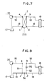
- FIGS. 7 to 10 show another embodiment of the present invention and the same elements are provided with the same reference numerals as used in the previous embodiments.
- FIGS. 9 and 10 show the shifting mechanism of the rotary type comprising the switching valve 83 and the shift valve 85, in this embodiment, although the shifting mechanism may comprise one having the sole function as the shift valve 85.
- a valve case 91 defines a valve chamber 92 within the case, and the valve chamber is of a nearly round shape in section and has four ports a , b , c and d to each of which are units and devices are connected as shown in FIGS. 7 and 8.
- a cut-off portion 95 is formed on a opening end portion of the part b on the side of the port d , the cut-off portion constituting the restrictor.
- an inner peripheral surface 92a between the port a and the port c , an inner peripheral surface 92b between the port a and the port b , and an inner peripheral surface 92c between the port b and the port d are disposed in an arc form of the identical diameter around the center O.
- an inner peripheral surface 92d of the valve chamber 92 between the port c and the port d is disposed in an arc shape of the same diameter around the center O while three inner peripheral surfaces 92a to 92c are disposed in an arc form having a somewhat larger diameter.
- the valve body 93 of the rotary type is disposed in the valve chamber 92 so as to be rotatable around the center O and has two projections 93a and 93b. Outer peripheral surfaces of the projections 93a and 93b are formed in an arc shape around the center O.
- the valve body 93 may take a first position as shown in FIG. 9 and a second position as shown in FIG. 10.
- the first position of the valve body 93 is such that the projection 93a shuts a passage between the ports a and c off while the projection 93b shuts a passage between the ports b and d off, thereby allowing the port a to be communicated with the port b while commnunicating the port d with the port c .
- the equivalent circuit in the first position is the same as shown in FIG. 6.
- FIG. 10 In the second position as shown in FIG. 10, although the projection 93a is located in a position between the port c and the port d , a first restrictor is formed between the projection 93a and the inner peripheral surface 92d because the inner peripheral surface 92d has a diameter as large as the diameter of the projection 93a, thereby communicating the port c with the port d .
- the projection 93b is located in such a position between the ports a and b to close the port b , thereby shutting a passage between the ports b and c off.
- a cut-off portion formed on an opening end of the port b serves as a second restrictor which in turn is allowed to be communicated with the port d .
- the equivalent circuit of FIG. 10 showing the second position is shown in FIG. 8.
- the valve body 93 as shown hereinabove is driven by means of the control unit 51.
Landscapes
- Engineering & Computer Science (AREA)
- Chemical & Material Sciences (AREA)
- Combustion & Propulsion (AREA)
- Transportation (AREA)
- Mechanical Engineering (AREA)
- Steering-Linkage Mechanisms And Four-Wheel Steering (AREA)
Applications Claiming Priority (2)
| Application Number | Priority Date | Filing Date | Title |
|---|---|---|---|
| JP16908889A JPH075093B2 (ja) | 1989-06-30 | 1989-06-30 | 車両の後輪操舵装置 |
| JP169088/89 | 1989-06-30 |
Publications (2)
| Publication Number | Publication Date |
|---|---|
| EP0405614A2 true EP0405614A2 (fr) | 1991-01-02 |
| EP0405614A3 EP0405614A3 (en) | 1991-05-08 |
Family
ID=15880107
Family Applications (1)
| Application Number | Title | Priority Date | Filing Date |
|---|---|---|---|
| EP19900112620 Ceased EP0405614A3 (en) | 1989-06-30 | 1990-07-02 | Rear wheel steering system for a vehicle |
Country Status (2)
| Country | Link |
|---|---|
| EP (1) | EP0405614A3 (fr) |
| JP (1) | JPH075093B2 (fr) |
Family Cites Families (3)
| Publication number | Priority date | Publication date | Assignee | Title |
|---|---|---|---|---|
| GB8529601D0 (en) * | 1985-12-02 | 1986-01-08 | Lotus Group Plc | Vehicle with front & rear wheel steering |
| JPS63273038A (ja) * | 1987-05-01 | 1988-11-10 | Mazda Motor Corp | 車載制御機器の電源異常検出装置 |
| DE3811312A1 (de) * | 1988-04-02 | 1989-10-19 | Bosch Gmbh Robert | Doppeltwirkender arbeitszylinder |
-
1989
- 1989-06-30 JP JP16908889A patent/JPH075093B2/ja not_active Expired - Lifetime
-
1990
- 1990-07-02 EP EP19900112620 patent/EP0405614A3/en not_active Ceased
Also Published As
| Publication number | Publication date |
|---|---|
| JPH075093B2 (ja) | 1995-01-25 |
| JPH0332981A (ja) | 1991-02-13 |
| EP0405614A3 (en) | 1991-05-08 |
Similar Documents
| Publication | Publication Date | Title |
|---|---|---|
| EP0682618B1 (fr) | Systeme a quatre roues directrices pour vehicule | |
| US4811805A (en) | Rear-wheel steering apparatus | |
| US5086863A (en) | All-wheel steering system for motor vehicles | |
| KR950004313B1 (ko) | 4륜 구동형 작업차 | |
| US5293953A (en) | Rear wheel steering system for a vehicle | |
| US4640379A (en) | Vehicle steering control system | |
| EP0405614A2 (fr) | Système de direction des roues arrières d'un véhicule | |
| EP0284022B1 (fr) | Direction à quatre roues directrices | |
| JPH0825482B2 (ja) | 車両の後輪操舵装置 | |
| JPS61196875A (ja) | 4輪操舵装置 | |
| JP3942768B2 (ja) | リヤステアリング装置 | |
| US4846296A (en) | Hydraulic fluid pressure control system for use with power assist steering | |
| JP2617750B2 (ja) | 4輪操舵装置 | |
| JP2580735B2 (ja) | 前後輪操舵車の後輪操舵制御装置 | |
| JP2666342B2 (ja) | 4輪操舵装置 | |
| JP2517578B2 (ja) | 車両の後輪操舵装置 | |
| JPS62131878A (ja) | 安全装置を備えた車両の4輪操舵装置 | |
| JPH0414272Y2 (fr) | ||
| KR950017621A (ko) | 4륜 조향 시스템 | |
| JP2503540B2 (ja) | 4輪操舵車両の油圧式後輪舵取機構 | |
| JPH078354Y2 (ja) | 4輪操舵装置 | |
| JPS60169369A (ja) | 車両の4輪操舵装置 | |
| JPS63184574A (ja) | 4輪操舵装置 | |
| JP2954243B2 (ja) | パワーステアリング装置 | |
| JPH064421B2 (ja) | 4輪操舵装置 |
Legal Events
| Date | Code | Title | Description |
|---|---|---|---|
| PUAI | Public reference made under article 153(3) epc to a published international application that has entered the european phase |
Free format text: ORIGINAL CODE: 0009012 |
|
| AK | Designated contracting states |
Kind code of ref document: A2 Designated state(s): DE FR GB |
|
| PUAL | Search report despatched |
Free format text: ORIGINAL CODE: 0009013 |
|
| AK | Designated contracting states |
Kind code of ref document: A3 Designated state(s): DE FR GB |
|
| 17P | Request for examination filed |
Effective date: 19910709 |
|
| 17Q | First examination report despatched |
Effective date: 19920908 |
|
| STAA | Information on the status of an ep patent application or granted ep patent |
Free format text: STATUS: THE APPLICATION HAS BEEN REFUSED |
|
| 18R | Application refused |
Effective date: 19950216 |