EP0406708B1 - Pièce de connexion pour arbre cardan capable d'être équipée avec des poids d'équilibrage et procédé d'équilibrage - Google Patents
Pièce de connexion pour arbre cardan capable d'être équipée avec des poids d'équilibrage et procédé d'équilibrage Download PDFInfo
- Publication number
- EP0406708B1 EP0406708B1 EP90112386A EP90112386A EP0406708B1 EP 0406708 B1 EP0406708 B1 EP 0406708B1 EP 90112386 A EP90112386 A EP 90112386A EP 90112386 A EP90112386 A EP 90112386A EP 0406708 B1 EP0406708 B1 EP 0406708B1
- Authority
- EP
- European Patent Office
- Prior art keywords
- flange
- connecting part
- apertures
- balancing
- plastic
- Prior art date
- Legal status (The legal status is an assumption and is not a legal conclusion. Google has not performed a legal analysis and makes no representation as to the accuracy of the status listed.)
- Expired - Lifetime
Links
Images

Classifications
-
- F—MECHANICAL ENGINEERING; LIGHTING; HEATING; WEAPONS; BLASTING
- F16—ENGINEERING ELEMENTS AND UNITS; GENERAL MEASURES FOR PRODUCING AND MAINTAINING EFFECTIVE FUNCTIONING OF MACHINES OR INSTALLATIONS; THERMAL INSULATION IN GENERAL
- F16F—SPRINGS; SHOCK-ABSORBERS; MEANS FOR DAMPING VIBRATION
- F16F15/00—Suppression of vibrations in systems; Means or arrangements for avoiding or reducing out-of-balance forces, e.g. due to motion
- F16F15/28—Counterweights, i.e. additional weights counterbalancing inertia forces induced by the reciprocating movement of masses in the system, e.g. of pistons attached to an engine crankshaft; Attaching or mounting same
-
- F—MECHANICAL ENGINEERING; LIGHTING; HEATING; WEAPONS; BLASTING
- F16—ENGINEERING ELEMENTS AND UNITS; GENERAL MEASURES FOR PRODUCING AND MAINTAINING EFFECTIVE FUNCTIONING OF MACHINES OR INSTALLATIONS; THERMAL INSULATION IN GENERAL
- F16C—SHAFTS; FLEXIBLE SHAFTS; ELEMENTS OR CRANKSHAFT MECHANISMS; ROTARY BODIES OTHER THAN GEARING ELEMENTS; BEARINGS
- F16C3/00—Shafts; Axles; Cranks; Eccentrics
- F16C3/02—Shafts; Axles
-
- F—MECHANICAL ENGINEERING; LIGHTING; HEATING; WEAPONS; BLASTING
- F16—ENGINEERING ELEMENTS AND UNITS; GENERAL MEASURES FOR PRODUCING AND MAINTAINING EFFECTIVE FUNCTIONING OF MACHINES OR INSTALLATIONS; THERMAL INSULATION IN GENERAL
- F16F—SPRINGS; SHOCK-ABSORBERS; MEANS FOR DAMPING VIBRATION
- F16F15/00—Suppression of vibrations in systems; Means or arrangements for avoiding or reducing out-of-balance forces, e.g. due to motion
- F16F15/32—Correcting- or balancing-weights or equivalent means for balancing rotating bodies, e.g. vehicle wheels
- F16F15/322—Correcting- or balancing-weights or equivalent means for balancing rotating bodies, e.g. vehicle wheels the rotating body being a shaft
Definitions
- the invention relates to a connecting part for cardan shafts, with a drive-side centering, a radial flange and a shaft-side connecting piece for connection to a cardan shaft of a motor vehicle.
- a comparable connection part is known from EP-A-0 318 818.
- Such connecting parts are used for connection to the drive units of a motor vehicle with the cardan shaft leading to the driven wheels.
- the object of the present invention is to provide a connecting part for the propeller shaft of a motor vehicle, which can be produced and balanced with little effort.
- the flange is a plastic injection molded part and is provided in its radially outer region with a plurality of shaped openings for receiving balancing weights.
- the connection part is produced as a plastic injection-molded part, the balancing bores in the flange being preformed during manufacture.
- the arrangement of the same in the flange facilitates accessibility.
- the openings are advantageously designed as axially extending blind holes, which are arranged in particular on a partial circle of the flange which runs concentrically to the centering.
- Manufacture of the connecting part from thermoplastic deformable plastic facilitates the later fixation of individual introduced balancing weights.
- Another object of the invention is to provide a simple method for balancing the connection part for the propeller shaft of a motor vehicle.
- balancing weights are inserted into openings which are preformed in the flange and are secured in their position by thermoplastic deformation of the flange.
- the flange in the edge area can be heated by means of ultrasound to secure the balancing weights and then mechanically deformed.
- hot stamping in the area of the individual balancing weights used using a suitable tool, e.g. a soldering iron possible.
- a suitable tool e.g. a soldering iron
- conventional fastening methods such as gluing can also be used.
- Another inexpensive design can include elastic knobs or edges on the edge of the openings, which spring back after the larger diameter weights are pressed in and secure them.
- the means can be molded into the flange or mechanically worked out.
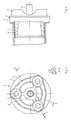
- a plastic injection molded part which consists essentially of a radially extending flange 2, integrally molded on this flange 2, axially extending ribs 3 and a drive-side centering 5.
- threaded plugs 4 are provided, which are made of metal and are provided with knurling in the plastic of the flange 2 for better connection.
- a connecting piece 6 is integrally formed on the flange 2 on the shaft side axially opposite the centering 5, which serves to connect to a cardan shaft 7, also shown here and made of plastic.
- the cardan shaft 7 is preferably glued to the connector 1.
- the flange 2 is provided with a large number of openings 9, which are molded in at the same time as this component is produced by the plastic injection molding process.
- a large number of openings 9 are provided, which are evenly distributed on a pitch circle 10 which runs concentrically with the centering 5.
- balancing weights 11 can be inserted into the corresponding openings 9.
- the balancing weights 11 are preferably made of metal.
- a balancing weight 11 is fixed and held in position after insertion by a plastically deformed edge 12 of the flange 2.
- the thermoplastic deformation of the edge 12 takes place after heating by means of ultrasound or by hot stamping.
- elastic knobs 8 are provided on the edges of the openings 9, which narrow the cross section and secure an imprinted balance weight.
Landscapes
- Engineering & Computer Science (AREA)
- General Engineering & Computer Science (AREA)
- Mechanical Engineering (AREA)
- Physics & Mathematics (AREA)
- Acoustics & Sound (AREA)
- Aviation & Aerospace Engineering (AREA)
- Ocean & Marine Engineering (AREA)
- Testing Of Balance (AREA)
- Motor Power Transmission Devices (AREA)
- Manufacture Of Motors, Generators (AREA)
- Shafts, Cranks, Connecting Bars, And Related Bearings (AREA)
Claims (9)
- Pièce de raccordement pour un arbre de cardan, comprenant un centrage du côté entraînement, une bride radiale et un manchon de raccordement du côté arbre, en vue du raccordement avec un arbre de cardan d'un véhicule automobile, caractérisée en ce que la bride (2) est une pièce de matière plastique moulée par injection et en ce qu'elle pourvue dans sa région radiale extérieure d'une pluralité d'ouvertures (9) formées en creux afin de recevoir des poids d'équilibrage (11).
- Pièce de raccordement selon la revendication 1, caractérisée en ce que les ouvertures (9) sont des trous borgnes qui s'étendent en direction axiale.
- Pièce de raccordement selon l'une ou l'autre des revendications 1 et 2, caractérisée en ce que les ouvertures (9) comprennent des moyens (8) à déformation élastique afin de rétrécir la section d'ouverture.
- Pièce de raccordement selon l'une quelconque des revendications 1 à 3, caractérisée en ce que les ouvertures (9) sont prévues sur un cercle partiel (10) de la bride (2) qui s'étend concentriquement au centrage (5).
- Pièce de raccordement selon l'une quelconque des revendications 1 à 4, caractérisée en ce que la bride (2) est réalisée en une matière plastique thermoplastique.
- Procédé d'équilibrage d'une pièce de raccordement en matière plastique qui comporte un centrage du côté entraînement, une bride radiale et un manchon de raccordement côté arbre en vue du raccordement avec un arbre de cardan d'un véhicule automobile, selon une ou plusieurs des revendications 1 à 5, caractérisé en ce que l'on met en place des poids d'équilibrage adaptés en diamètre dans des ouvertures dans la bride déterminées par des mesures de rotation, et en ce qu'on les assure en position par déformation plastique de la bride.
- Procédé selon la revendication 6, caractérisé en ce que les poids d'équilibrage sont assurés dans les perçages d'équilibrage par déformation thermoplastique de la matière plastique par réchauffement au moyen d'ultrasons.
- Procédé selon la revendication 6, caractérisé en ce que les poids d'équilibrage sont assurés dans les perçages d'équilibrage par déformation thermoplastique de la matière plastique au moyen d'une impression à chaud.
- Procédé d'équilibrage d'une pièce de raccordement en matière plastique, qui comprend un centrage du côté entraînement, une bride radiale et un manchon de raccordement côté arbre, en vue du raccordement à un arbre de cardan d'un véhicule automobile, selon l'une ou plusieurs des revendications 3 à 5, caractérisé en ce que l'on met en place des poids d'équilibrage dans la bride, dans des ouvertures déterminées par des mesures de rotation, lesdits poids d'équilibrage ayant un diamètre supérieur aux moyens de rétrécissement, et étant assurés dans leur position par retour élastique desdits moyens.
Applications Claiming Priority (2)
| Application Number | Priority Date | Filing Date | Title |
|---|---|---|---|
| DE3921862 | 1989-07-04 | ||
| DE3921862 | 1989-07-04 |
Publications (3)
| Publication Number | Publication Date |
|---|---|
| EP0406708A2 EP0406708A2 (fr) | 1991-01-09 |
| EP0406708A3 EP0406708A3 (en) | 1991-12-18 |
| EP0406708B1 true EP0406708B1 (fr) | 1994-04-06 |
Family
ID=6384206
Family Applications (1)
| Application Number | Title | Priority Date | Filing Date |
|---|---|---|---|
| EP90112386A Expired - Lifetime EP0406708B1 (fr) | 1989-07-04 | 1990-06-29 | Pièce de connexion pour arbre cardan capable d'être équipée avec des poids d'équilibrage et procédé d'équilibrage |
Country Status (5)
| Country | Link |
|---|---|
| US (1) | US5133226A (fr) |
| EP (1) | EP0406708B1 (fr) |
| JP (1) | JPH0341209A (fr) |
| DD (1) | DD296251A5 (fr) |
| DE (1) | DE59005237D1 (fr) |
Cited By (1)
| Publication number | Priority date | Publication date | Assignee | Title |
|---|---|---|---|---|
| CN106870635A (zh) * | 2015-12-14 | 2017-06-20 | 现代自动车株式会社 | 用于车辆传动轴的动态减震器 |
Families Citing this family (6)
| Publication number | Priority date | Publication date | Assignee | Title |
|---|---|---|---|---|
| US6450042B1 (en) * | 2000-03-02 | 2002-09-17 | Micro Motion, Inc. | Apparatus for and a method of fabricating a coriolis flowmeter formed primarily of plastic |
| US20050228331A1 (en) * | 2004-04-01 | 2005-10-13 | Tseng Yung-Lung | Gripping bandage |
| US7361092B2 (en) * | 2006-01-30 | 2008-04-22 | Chrysler Llc | Balance assembly for coupling first and second rotating members |
| US7617871B2 (en) * | 2007-01-29 | 2009-11-17 | Halliburton Energy Services, Inc. | Hydrajet bottomhole completion tool and process |
| CN103486130A (zh) * | 2013-08-21 | 2014-01-01 | 蚌埠市广瑞机械有限公司 | 一种新型联动轴 |
| DE102015214818A1 (de) * | 2015-08-04 | 2017-02-09 | Volkswagen Aktiengesellschaft | Wuchtscheibe für ein drehbares Bauteil |
Citations (1)
| Publication number | Priority date | Publication date | Assignee | Title |
|---|---|---|---|---|
| EP0318818A1 (fr) * | 1987-12-03 | 1989-06-07 | Gkn Automotive Aktiengesellschaft | Dispositif avec une fixation par adhésif entre un moyeu et un tube |
Family Cites Families (16)
| Publication number | Priority date | Publication date | Assignee | Title |
|---|---|---|---|---|
| GB891902A (en) * | 1958-01-24 | 1962-03-21 | Licentia Gmbh | Balancing the inductors of electrical machines |
| GB815356A (en) * | 1958-02-22 | 1959-06-24 | Gelenkwellenbau Gmbh | Improvements relating to the counterbalancing of rotary shafts |
| US3838464A (en) * | 1972-10-24 | 1974-09-24 | Nashua Corp | Retaining ring for magnetic disc pack assembly |
| SE401548B (sv) * | 1976-09-22 | 1978-05-16 | Volvo Penta Ab | Svenghjul |
| SU984796A2 (ru) * | 1981-01-26 | 1982-12-30 | Предприятие П/Я В-2969 | Инерционный привод |
| CA1208041A (fr) * | 1982-04-26 | 1986-07-22 | William P. Ellis, Jr. | Methode d'equilibrage d'organes mecaniques |
| EP0143200A3 (fr) * | 1983-09-02 | 1987-03-25 | International Technical Research S.A.H. | Dispositif pour la fixation des poids correcteurs |
| EP0161326A1 (fr) * | 1984-05-16 | 1985-11-21 | Mitsubishi Denki Kabushiki Kaisha | Volant d'inertie |
| JPS6185501A (ja) * | 1984-10-03 | 1986-05-01 | Ngk Insulators Ltd | セラミツクスロ−タ−のバランス修正方法並びにそれに用いられる修正治具 |
| JPS6237001U (fr) * | 1985-08-19 | 1987-03-05 | ||
| JPS6263236A (ja) * | 1985-09-13 | 1987-03-19 | Copal Electron Co Ltd | 回転体 |
| US4711610A (en) * | 1986-04-04 | 1987-12-08 | Machine Technology, Inc. | Balancing chuck |
| DE3637256A1 (de) * | 1986-11-03 | 1988-05-11 | Bbc Brown Boveri & Cie | Rotor |
| US4721445A (en) * | 1986-12-31 | 1988-01-26 | Compression Technologies, Inc. | Outer envelope trochoidal rotary device having a rotor assembly having peripheral reliefs |
| US4835827A (en) * | 1987-09-08 | 1989-06-06 | United Technologies Corporation | Method of balancing a rotor |
| US4889011A (en) * | 1988-11-07 | 1989-12-26 | Steahly Charles W | Detachable flywheel weights for altering motorcycle engine performance |
-
1990
- 1990-06-25 US US07/543,146 patent/US5133226A/en not_active Expired - Fee Related
- 1990-06-29 DE DE90112386T patent/DE59005237D1/de not_active Expired - Fee Related
- 1990-06-29 EP EP90112386A patent/EP0406708B1/fr not_active Expired - Lifetime
- 1990-07-03 DD DD90342451A patent/DD296251A5/de not_active IP Right Cessation
- 1990-07-04 JP JP2175454A patent/JPH0341209A/ja active Pending
Patent Citations (1)
| Publication number | Priority date | Publication date | Assignee | Title |
|---|---|---|---|---|
| EP0318818A1 (fr) * | 1987-12-03 | 1989-06-07 | Gkn Automotive Aktiengesellschaft | Dispositif avec une fixation par adhésif entre un moyeu et un tube |
Cited By (2)
| Publication number | Priority date | Publication date | Assignee | Title |
|---|---|---|---|---|
| CN106870635A (zh) * | 2015-12-14 | 2017-06-20 | 现代自动车株式会社 | 用于车辆传动轴的动态减震器 |
| CN106870635B (zh) * | 2015-12-14 | 2020-04-28 | 现代自动车株式会社 | 用于车辆传动轴的动态减震器 |
Also Published As
| Publication number | Publication date |
|---|---|
| DE59005237D1 (de) | 1994-05-11 |
| JPH0341209A (ja) | 1991-02-21 |
| US5133226A (en) | 1992-07-28 |
| EP0406708A3 (en) | 1991-12-18 |
| DD296251A5 (de) | 1991-11-28 |
| EP0406708A2 (fr) | 1991-01-09 |
Similar Documents
| Publication | Publication Date | Title |
|---|---|---|
| DE4309570B4 (de) | Kupplung in Modularbauweise sowie Verfahren zur Montage derselben | |
| DE3828018C2 (de) | Verfahren zum Herstellen eines Verbundes aus einer metallenen Innenhülse und einem Rohr aus Faser- Kunststoff-Material sowie danach hergestellter Verbund | |
| DE102017122122B4 (de) | Verfahren zur Herstellung einer Rotorwelle und Rotorwelle | |
| DE69016707T2 (de) | Dynamischer Dämpfer. | |
| DE4328153C2 (de) | Ringförmiges Maschinenteil und Verfahren zu dessen Herstellung | |
| EP0406708B1 (fr) | Pièce de connexion pour arbre cardan capable d'être équipée avec des poids d'équilibrage et procédé d'équilibrage | |
| DE102004051566B4 (de) | Nachgiebige Buchsenanordnung | |
| DE102020203483A1 (de) | Rotor eines Elektromotors | |
| DE102005055800B4 (de) | Vorrichtung zur Dämpfung von Torsionsschwingungen und Anordnung | |
| DE102020203487A1 (de) | Rotor eines Elektromotors | |
| DE19745690A1 (de) | Antriebsvorrichtung für eine Wischanlage, insbesondere für Scheiben an Kraftfahrzeugen | |
| DE2130247B2 (de) | Elastische Kupplung | |
| DE10335810B4 (de) | Antriebsstrang mit einem Motor-Generatorrotor, der einen Befestigungsring zur Drehmomentübertragung aufweist | |
| DE68920555T2 (de) | Verfahren zum Montieren und Herstellen eines Laugenbehälters für Waschmaschinen und auf diese Weise hergestellter Laugenbehälter. | |
| DE69806177T2 (de) | Elastomerkupplung mit komposit-klotz | |
| DE3544500C2 (de) | Kupplungsscheibe mit plastisch angeformten Kunststoff-Lagerelementen | |
| DE102005042839A1 (de) | Gelenkwelle | |
| DE102010053933A1 (de) | Rotationseinrichtung sowie Verfahren zum Auswuchten einer Rotationseinrichtung | |
| DE102019114052A1 (de) | Hybridmodul mit einem einen Stator aufnehmenden Gehäuse; sowie Antriebsstrang | |
| DE10248372B4 (de) | Gegenbahngelenk | |
| DE202022106941U1 (de) | Entkoppelte Riemenscheibe mit integrierter Unwucht | |
| DE3539704A1 (de) | Kraftuebertragungsanordnung, insbesondere fuer kraftfahrzeuge, hydraulisches kupplungsorgan mit einer solchen kraftuebertragungsanordnung und zu deren ausbildung geeignete vorrichtung zum abgreifen der bewegung sowie verfahren zur herstellung dieser vorrichtung | |
| DE19938461A1 (de) | Drehelastische Kupplung und Verfahren zu ihrer Herstellung | |
| DE60317151T2 (de) | Elektromotor | |
| DE102006001200A1 (de) | Antriebswellenkupplung |
Legal Events
| Date | Code | Title | Description |
|---|---|---|---|
| PUAI | Public reference made under article 153(3) epc to a published international application that has entered the european phase |
Free format text: ORIGINAL CODE: 0009012 |
|
| AK | Designated contracting states |
Kind code of ref document: A2 Designated state(s): DE ES FR GB IT |
|
| PUAL | Search report despatched |
Free format text: ORIGINAL CODE: 0009013 |
|
| RHK1 | Main classification (correction) |
Ipc: F16C 3/02 |
|
| AK | Designated contracting states |
Kind code of ref document: A3 Designated state(s): DE ES FR GB IT |
|
| 17P | Request for examination filed |
Effective date: 19920110 |
|
| 17Q | First examination report despatched |
Effective date: 19930903 |
|
| GRAA | (expected) grant |
Free format text: ORIGINAL CODE: 0009210 |
|
| AK | Designated contracting states |
Kind code of ref document: B1 Designated state(s): DE ES FR GB IT |
|
| PG25 | Lapsed in a contracting state [announced via postgrant information from national office to epo] |
Ref country code: IT Free format text: LAPSE BECAUSE OF FAILURE TO SUBMIT A TRANSLATION OF THE DESCRIPTION OR TO PAY THE FEE WITHIN THE PRE;WARNING: LAPSES OF ITALIAN PATENTS WITH EFFECTIVE DATE BEFORE 2007 MAY HAVE OCCURRED AT ANY TIME BEFORE 2007. THE CORRECT EFFECTIVE DATE MAY BE DIFFERENT FROM THE ONE RECORDED.SCRIBED TIME-LIMIT Effective date: 19940406 Ref country code: FR Effective date: 19940406 Ref country code: GB Effective date: 19940406 Ref country code: ES Free format text: THE PATENT HAS BEEN ANNULLED BY A DECISION OF A NATIONAL AUTHORITY Effective date: 19940406 |
|
| REF | Corresponds to: |
Ref document number: 59005237 Country of ref document: DE Date of ref document: 19940511 |
|
| EN | Fr: translation not filed | ||
| GBV | Gb: ep patent (uk) treated as always having been void in accordance with gb section 77(7)/1977 [no translation filed] |
Effective date: 19940406 |
|
| PLBE | No opposition filed within time limit |
Free format text: ORIGINAL CODE: 0009261 |
|
| STAA | Information on the status of an ep patent application or granted ep patent |
Free format text: STATUS: NO OPPOSITION FILED WITHIN TIME LIMIT |
|
| PG25 | Lapsed in a contracting state [announced via postgrant information from national office to epo] |
Ref country code: DE Effective date: 19950301 |
|
| 26N | No opposition filed |