EP0406868A2 - Kreiselpumpengehäuse - Google Patents
Kreiselpumpengehäuse Download PDFInfo
- Publication number
- EP0406868A2 EP0406868A2 EP90112870A EP90112870A EP0406868A2 EP 0406868 A2 EP0406868 A2 EP 0406868A2 EP 90112870 A EP90112870 A EP 90112870A EP 90112870 A EP90112870 A EP 90112870A EP 0406868 A2 EP0406868 A2 EP 0406868A2
- Authority
- EP
- European Patent Office
- Prior art keywords
- centrifugal pump
- bulged
- casing
- starting point
- casing shell
- Prior art date
- Legal status (The legal status is an assumption and is not a legal conclusion. Google has not performed a legal analysis and makes no representation as to the accuracy of the status listed.)
- Granted
Links
- 230000002093 peripheral effect Effects 0.000 claims abstract description 44
- 238000004804 winding Methods 0.000 claims abstract description 27
- 238000000034 method Methods 0.000 claims abstract description 18
- 238000000137 annealing Methods 0.000 claims abstract description 8
- XLYOFNOQVPJJNP-UHFFFAOYSA-N water Substances O XLYOFNOQVPJJNP-UHFFFAOYSA-N 0.000 claims abstract description 4
- 230000008093 supporting effect Effects 0.000 claims description 10
- 238000003825 pressing Methods 0.000 abstract description 9
- 239000012530 fluid Substances 0.000 description 14
- 239000007788 liquid Substances 0.000 description 9
- 238000003466 welding Methods 0.000 description 6
- 230000003247 decreasing effect Effects 0.000 description 5
- 229910000831 Steel Inorganic materials 0.000 description 2
- 238000005381 potential energy Methods 0.000 description 2
- 230000003014 reinforcing effect Effects 0.000 description 2
- 239000010959 steel Substances 0.000 description 2
- 238000007792 addition Methods 0.000 description 1
- 230000006866 deterioration Effects 0.000 description 1
- 230000002542 deteriorative effect Effects 0.000 description 1
- 238000007599 discharging Methods 0.000 description 1
- 230000000694 effects Effects 0.000 description 1
- 238000004519 manufacturing process Methods 0.000 description 1
- 230000003313 weakening effect Effects 0.000 description 1
Images


Classifications
-
- F—MECHANICAL ENGINEERING; LIGHTING; HEATING; WEAPONS; BLASTING
- F04—POSITIVE - DISPLACEMENT MACHINES FOR LIQUIDS; PUMPS FOR LIQUIDS OR ELASTIC FLUIDS
- F04D—NON-POSITIVE-DISPLACEMENT PUMPS
- F04D29/00—Details, component parts, or accessories
- F04D29/40—Casings; Connections of working fluid
- F04D29/42—Casings; Connections of working fluid for radial or helico-centrifugal pumps
-
- F—MECHANICAL ENGINEERING; LIGHTING; HEATING; WEAPONS; BLASTING
- F04—POSITIVE - DISPLACEMENT MACHINES FOR LIQUIDS; PUMPS FOR LIQUIDS OR ELASTIC FLUIDS
- F04D—NON-POSITIVE-DISPLACEMENT PUMPS
- F04D29/00—Details, component parts, or accessories
- F04D29/40—Casings; Connections of working fluid
- F04D29/42—Casings; Connections of working fluid for radial or helico-centrifugal pumps
- F04D29/426—Casings; Connections of working fluid for radial or helico-centrifugal pumps especially adapted for liquid pumps
- F04D29/4266—Casings; Connections of working fluid for radial or helico-centrifugal pumps especially adapted for liquid pumps made of sheet metal
-
- F—MECHANICAL ENGINEERING; LIGHTING; HEATING; WEAPONS; BLASTING
- F04—POSITIVE - DISPLACEMENT MACHINES FOR LIQUIDS; PUMPS FOR LIQUIDS OR ELASTIC FLUIDS
- F04D—NON-POSITIVE-DISPLACEMENT PUMPS
- F04D29/00—Details, component parts, or accessories
- F04D29/40—Casings; Connections of working fluid
- F04D29/42—Casings; Connections of working fluid for radial or helico-centrifugal pumps
- F04D29/426—Casings; Connections of working fluid for radial or helico-centrifugal pumps especially adapted for liquid pumps
- F04D29/428—Discharge tongues
Definitions
- the present invention relates to a centrifugal pump casing, and especially, to a centrifugal pump casing used in a centrifugal pump having a small size and capacity.
- centrifugal pump rotatably accommodating an impeller in its casing shell is well known.
- a casing shell 23 is integrally formed by means of pressing work, which has as a basic circle an inner peripheral circle 22 having a diameter slightly greater than the outer peripheral diameter 21 of the impeller 20, and the outer peripheral wall of the casing shell 23 is integrally formed with a bulged portion 23a bulging radially outwardly from the outer peripheral wall of the casing shell.
- the bulged portion extends from a winding starting point b of the casing shell in the circumferential direction to an end point c while its height gradually increases in the direction from the winding starting point to the end point.
- a discharge nozzle 25 is welded to the casing shell.
- the inside of the casing shell 23 is formed with a volute room A which has a cross-sectional area gradually increasing in the direction of the fluid flow direction.
- the end point of the volute room A is provided with guide 26 having a projecting shape for decreasing the flow resistance of the fluid flow towards the discharge nozzle 25.
- the necessary amount of the cross-sectional area of the volute room A at the end point c is determined on the basis of the fluid flow rate and the fluid flow speed.
- the prior art has another problem in that it is necessary to arrange a guide 26 having a projecting shape at the end point c of the volute room A to decrease the flow resistance of the fluid flow towards the exhaust nozzle 25. Without such a guide 26, the pump performance will be decreased.
- the object of the present invention is to provide a centrifugal pump casing which can overcome the above-mentioned problems of the prior art, and in which the bulged portion can be formed by a single pressing process without the need for annealing processes, and the pump performance is not decreased even if the projected guide is not provided at the end point of the volute room.
- a centrifugal pump casing comprises, a casing shell accommodating a rotary impeller therein and having as a basic circle an inner peripheral circle having a diameter greater than the diameter of the outer peripheral circle of said impeller.
- a bulged portion bulged radially outwardly is integrally formed on the outer peripheral wall of the casing shell. This bulged portion extends from a starting point remote from the winding starting point of the casing shell in a circumferential direction to an end point while gradually increasing in height in the dimension from the starting point to the end point.
- a pipe-like discharge nozzle is connected to the casing shell so that it extends between the end point where the bulged portion is highest and the winding starting point where no bulged portion is formed.
- the casing shell has as a basic circle an inner peripheral circle having a diameter greater than the diameter of the outer peripheral circle of the impeller, and the bulged portion bulging radially outwardly is formed on the outer peripheral wall of the casing shell so that it extends from a starting point remote from the winding starting point of the casing shell in a circumferential direction to an ending point while gradually increasing in height in the direction from the starting point to the ending point, the bulge height above the basic circle is not so great even at the ending point where a maximum height is reached, and, therefore, the bulged portion can be formed by a single pressing process without the need for an annealing process.
- the wall portion of the casing shell at the winding starting point may serve as a guide for discharge water, and accordingly, there is required no guide having a projecting shape, which is required in the prior art.
- a wall portion of the casing shell on its suction side is formed to have a concave mirror shape with the pump suction port being open at the central portion thereof and the inside of the concave wall portion is provided with an annular supporting plate.
- An outer peripheral portion of the supporting plate is secured to an inner surface of the wall portion while an inner peripheral portion thereof is bent toward the impeller and formed in a cylindrical shape.
- a connecting pipe is disposed to extend between the cylindrically shaped inner peripheral portion and the pump suction port included in the wall portion, and one end thereof is welded to the pump suction port in the wall portion while the other end thereof is press fitted within the inner peripheral portion of the supporting plate.
- a nozzle element having the shape of a bent pipe is disposed within the pipe-like discharge nozzle.
- An outlet portion of the nozzle element is fixed to the inside of the discharge nozzle and an inlet opening of the nozzle element is directed toward the volute room at the end point where the bulged height of the bulged portion is highest.
- the sectional area of the inlet opening of the nozzle element is made substantially the same as the sectional area of the volute room at its end point and the sectional area of the nozzle element is gradually increased toward the outlet portion thereof.
- centrifugal pump casings according to embodiments of the present invention will be described below.
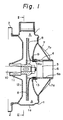
- numeral 1 denotes a casing shell of a centrifugal pump, which is formed by deep drawing a single steel plate using a pressing machine.
- the casing shell 1 is integrally formed with a fixing flange 2 at one end thereof, and with a suction port 3 at the other end thereof.
- the casing shell 1 is connected to a bracket (not shown) of a motor through the fixing flange 2.
- a connecting pipe 4 To the suction port 3 of the casing shell 1 is connected a connecting pipe 4 by welding, which has a suction port 6 having a female screw 6a on its inner surface.
- a reinforcing cover member 7 having a substantially truncated cone shape and fixed thereto by welding.
- cover member 7 On the outer surface of the cover member 7 are integrally formed a plurality of radially extending reinforcing bulged portions 7a, 7a, -- 7a.
- an impeller 8 which is fixed on a boss 9.
- the boss 9 is connected with a free end of a main shaft 10.
- the main shaft 10 is rotatably supported by a bearing (not shown) and is provided thereon with a seal means 11, which is supported by a casing cover 12 fixed to the casing shell 1.
- a ring 13 having a U-shaped cross section for preventing the fluid from flowing backward between the edge portion 8a of the impeller 8 and the casing shell 1.
- the casing shell 1 is formed to have an inner peripheral circle 15 as a basic circle, the diameter of which is greater than that of the outer peripheral circle 16 of the impeller 8. It is preferred to determine the diameter of the basic circle in a range of 1.05 to 1.10 times of the diameter of the outer peripheral circle of the impeller. When determined below 1.05, the clearance between the circles becomes too narrow, thereby generating considerable noise. On the other hand, when determined above 1.10, the clearance become too wide, thereby deteriorating the performance of the pump.
- a bulged portion 1a which is radially outwardly bulged with hight gradually increasing as going from a starting point b , which is remote in the circumferential direction from the winding starting point a of the casing shell 1, to an ending point c . It is preferred to determine the position of the starting point b remote from the winding starting point a by 90° to 180° in the circumferential direction.
- the bulge height of the bulged portion 1a becomes too high at the end point c , thereby making it impossible, as will be mentioned later, to obtain the complete bulged shape through only one forming process.
- the starting point b is positioned beyond 180°, the effect of providing the bulged portion 1a may be lost.
- the height of the bulged portion 1a is maximum at the ending point c .
- a pipe-like discharge nozzle 18 is connected to the casing shell by welding so that it extends between the ending point c and the winding starting point a at which no bulged portion is formed.
- a straight pipe or deverging pipe having a varying diameter may be used as the exhaust nozzle 18.
- the required maximum cross-sectional area of the volute room at the ending point c is determined from the fluid flow rate and the fluid flow speed required for the centrifugal pump.
- the diameter of the inner peripheral circle 15 defining the basic circle is greater enough at the winding starting point a of the casing shell 1 in comparison to the diameter of the outer peripheral circle 16 of the impeller 8.
- the bulge height h above the basic circle 15 at the ending point c is not required to be so high, and, the necessary cross-sectional area at point c can be obtained by providing a relatively small bulge.
- the bulged portion 1a can be formed through only one bulging process without the need for an annealing process, because the bulge height of the bulged portion 1a at the ending point c can be made relatively small.
- the gap in the radial direction between the inner peripheral circle 15 of the casing shell 1 and the outer peripheral circle 16 of the impeller 8 is made rather wide. It is known, however, that, in a centrifugal pump of small size and small capacity, even when the above-mentioned gap is wide to some degree, the backward fluid flow from the ending point c towards the winding starting point a is not so great as to cause a substantial deterioration in the pump's performance.
- the pipe-like discharge nozzle 18 is connected to the casing shell 1 by welding so that it extends between the end point c , where the bulge height is maximum, and the winding starting point a , where no bulged portion is formed, and since the difference in height between the end point c and the winding starting point a is not so great, the wall 1b of the casing shell 1 locating at the winding starting point a may serve as the guide used in prior arts, and as a result, any guide for discharging water is not required to be arranged.
- the function of the centrifugal pump having the above-mentioned arrangement is as follows.
- a main shaft 10 which is connected to a driving motor (not shown)
- the impeller 8 is rotated integrally thereby sucking the fluid through the suction port 3.
- the sucked fluid flows through the inside of the impeller 8, is given centrifugal force, and delivered from the peripheral portion thereof into the volute room A.
- the delivered fluid is moved in a circumferential direction (clockwise direction in Fig. 2) and discharged through the discharge nozzle 18 to the outside.
- the casing shell 1 has as a basic circle an inner peripheral circle 15 having a diameter greater than the diameter of the outer peripheral circle 16 of the impeller 8, and the bulged portion is bulged radially outwardly from the outer peripheral wall of the casing shell extending from a starting point b remote from the winding starting point a of the casing shell in a circumferential direction to an ending point c while gradually increasing the bulge height in the direction from said starting point to said ending point, the bulge height h above the basic circle 15 is not so great even at the end point c where a maximum height is reached, and, therefore, the bulged portion can be formed through only one pressing process without the need for an annealing process.
- the pipe-like discharge nozzle 18 is connected to the casing shell so that it extends between the end point c where the bulged portion is highest and the winding starting a point where no bulged portion is formed, the wall portion 1b of the casing shell at the winding starting point may serve as a guide, and accordingly, there is not required any guide having a projecting shape, which is required in the prior art.
- Fig. 3 shows another embodiment of the invention.
- a wall portion 30 of the casing shell 1 on its suction side is formed so as to have a concave mirror shape and the suction port 3 is open at the central portion thereof.
- an annular supporting plate 32 and an outer peripheral portion 32a thereof is secured to an inner surface 30a of the wall portion 30.
- An inner peripheral portion 32b of the supporting plate 32 is bent toward the impeller 8 and formed in a cylindrical shape and the connecting pipe 4 is disposed to extend between the cylindrically shaped inner peripheral portion 32b and the pump suction port 3 in the wall portion 30.
- One end 4a of the connecting pipe 4 is welded to the pump suction port 3 included in the wall portion 30, while the other end 4b of the connecting pipe 4 is press fitted within the inner peripheral portion 32b.
- An annular stepped portion 33 is formed on the inner surface of the other end portion 4b of the connecting pipe 4 and the edge portion 8a of the impeller 8 is loosely fitted within the stepped portion 33.
- a liner ring not shown is provided between the stepped portion and the impeller edge portion.
- the wall portion 30 is formed to have a concave mirror shape and the annular supporting plate 32 is secured to the inside of the wall portion 30, an internal pressure caused by pump operation is born by a double wall structure constituted by the supporting plate 32 and the wall portion 30.
- the strength of the casing shell 1 against the internal pressure is increased and consequently strain imposed on the casing shell 1 caused by the internal pressure may be effectively limited.
- Fig. 4 shows a further embodiment of the present invention.
- a nozzle element 35 having the shape of a bent pipe is disposed within pipe-like discharge nozzle 18.
- An outlet portion 35a of the nozzle element 35 is fixed to the inside of the discharge nozzle 18 and the opening of an inlet portion 35b of the nozzle element 35 is directed toward the volute room A at the end point c where the bulged height h of the bulged portion 1a is highest.
- the sectional area of the opening of the inlet portion 35b is made substantially the same as the sectional area of the volute room A at its end point c and the sectional area of the nozzle element 35 is gradually increased toward the outlet portion 35a thereof.
- a pumped liquid flowing with high velocity from the volute room A toward the discharge nozzle enters the nozzle element 35 and the velocity of the liquid is gradually decreased in this nozzle element 35 and, thereafter, the liquid is discharged from the discharge nozzle 15.
- a part of the kinetic energy of the pumped liquid is effectively converted into potential energy to increase pump pressure during its decrease in velocity and, therefore, the pump performance can be improved.
- the nozzle element 35 is formed of a moderately bent pipe, the pumped liquid is effectively discharged from the volute room A through the discharge nozzle 15 without causing substantial turbulance.
Landscapes
- Engineering & Computer Science (AREA)
- Mechanical Engineering (AREA)
- General Engineering & Computer Science (AREA)
- Structures Of Non-Positive Displacement Pumps (AREA)
Applications Claiming Priority (4)
| Application Number | Priority Date | Filing Date | Title |
|---|---|---|---|
| JP17319489 | 1989-07-05 | ||
| JP173194/89 | 1989-07-05 | ||
| JP2156762A JP2809487B2 (ja) | 1989-07-05 | 1990-06-14 | 遠心ポンプケーシング |
| JP156762/90 | 1990-06-14 |
Publications (3)
| Publication Number | Publication Date |
|---|---|
| EP0406868A2 true EP0406868A2 (de) | 1991-01-09 |
| EP0406868A3 EP0406868A3 (en) | 1991-07-03 |
| EP0406868B1 EP0406868B1 (de) | 1996-05-01 |
Family
ID=26484430
Family Applications (1)
| Application Number | Title | Priority Date | Filing Date |
|---|---|---|---|
| EP90112870A Expired - Lifetime EP0406868B1 (de) | 1989-07-05 | 1990-07-05 | Kreiselpumpengehäuse |
Country Status (9)
| Country | Link |
|---|---|
| US (1) | US5184937A (de) |
| EP (1) | EP0406868B1 (de) |
| JP (1) | JP2809487B2 (de) |
| KR (1) | KR0137654B1 (de) |
| AT (1) | ATE137566T1 (de) |
| DE (3) | DE69026758T2 (de) |
| DK (1) | DK0406868T3 (de) |
| ES (1) | ES2088924T3 (de) |
| IT (2) | IT220470Z2 (de) |
Cited By (8)
| Publication number | Priority date | Publication date | Assignee | Title |
|---|---|---|---|---|
| DE4101611A1 (de) * | 1991-01-11 | 1992-07-16 | Ebara Corp | Gehaeuse fuer eine kreiselpumpe aus metallblech |
| US5258100A (en) * | 1992-02-28 | 1993-11-02 | Kamyr, Inc. | Minimizing gas separation in a mixer outlet |
| DE4329019A1 (de) * | 1993-08-28 | 1995-03-02 | Klein Schanzlin & Becker Ag | Kreiselpumpengehäuse in Blechbauweise |
| WO2000026541A1 (fr) * | 1998-10-30 | 2000-05-11 | Yangjiang New Yuehua Stainless Steel Pump Co. Ltd. | Pompe centrifuge formee par assemblage par soudure et par emboutissage et son procede de fabrication |
| CN100404874C (zh) * | 2006-01-21 | 2008-07-23 | 阳江市新力工业有限公司 | 一种冲压焊接食品泵 |
| DE102008064099A1 (de) * | 2008-12-19 | 2010-07-01 | Bühler Motor GmbH | Kreiselpumpe mit einer feststehenden Achse |
| FR2958324A1 (fr) * | 2010-03-30 | 2011-10-07 | Snecma | Carter de turbomachine rigidifie |
| GB2502388A (en) * | 2012-05-25 | 2013-11-27 | Samsung Electro Mech | Blower impeller shaft mounting |
Families Citing this family (8)
| Publication number | Priority date | Publication date | Assignee | Title |
|---|---|---|---|---|
| JP2676450B2 (ja) * | 1991-01-11 | 1997-11-17 | 株式会社荏原製作所 | 板金製ポンプケーシング |
| DE4214026A1 (de) * | 1992-04-29 | 1993-11-04 | Klein Schanzlin & Becker Ag | Pumpengehaeuse |
| DE4311453C2 (de) * | 1993-04-07 | 1995-05-11 | Lutz Dipl Ing Komosa | Einrichtung für eine Tauchpumpe mit geschlossenem Laufrad |
| WO1999030039A1 (en) * | 1997-12-08 | 1999-06-17 | Ebara Corporation | Centrifugal pump |
| TWI256442B (en) * | 2004-03-18 | 2006-06-11 | Delta Electronics Inc | Centrifugal flow fan |
| US9695826B1 (en) * | 2012-06-28 | 2017-07-04 | James Harmon | Pitot tube pump and related methods |
| KR101775587B1 (ko) * | 2016-02-05 | 2017-09-08 | 주식회사 지트리비앤티 | 해수용 순환 펌프 |
| CN121383271B (zh) * | 2025-12-25 | 2026-02-27 | 杭州老板电器股份有限公司 | 油烟机及油烟机的使用方法 |
Family Cites Families (21)
| Publication number | Priority date | Publication date | Assignee | Title |
|---|---|---|---|---|
| US619736A (en) * | 1899-02-21 | Joseph edwards | ||
| US801304A (en) * | 1904-05-23 | 1905-10-10 | Samuel Cleland Davidson | Centrifugal fan or pump. |
| US1291037A (en) * | 1917-12-18 | 1919-01-14 | Alfred Ernest Lole | Rotary pump and the like. |
| US2268358A (en) * | 1939-03-13 | 1941-12-30 | Edward T Turner | Centrifugal pump |
| US2844100A (en) * | 1954-07-06 | 1958-07-22 | Kurt J Heinicke | Sheet metal centrifugal pump |
| CH368448A (de) * | 1959-02-27 | 1963-03-31 | Sulzer Ag | Verfahren zum Betrieb von Speicherkraftwerken mit einstufigen hydraulischen Maschinen |
| DE1453723A1 (de) * | 1963-07-19 | 1969-07-31 | Barske Ulrich Max | Kreiselpumpe,insbesondere fuer kleine bis mittlere Foerderstroeme |
| US3407995A (en) * | 1966-10-12 | 1968-10-29 | Lau Blower Co | Blower assembly |
| US3758227A (en) * | 1971-11-15 | 1973-09-11 | H Pollak | Device for varying the volute and throat of a centrifugal pump |
| JPS5175201A (en) * | 1974-12-25 | 1976-06-29 | Shigeru Osame | Uzumakihonpu to sonoseiho |
| US3967915A (en) * | 1975-01-27 | 1976-07-06 | Litzenberg David P | Centrifugal pump |
| JPS5735676A (en) * | 1980-08-09 | 1982-02-26 | Sumitomo Metal Ind Ltd | Production of edged and melt sprayed steel plate |
| JPS58211599A (ja) * | 1982-06-03 | 1983-12-09 | Hitachi Ltd | 小形ポンプ |
| DE3517498C3 (de) * | 1985-05-15 | 1993-12-02 | Klein Schanzlin & Becker Ag | Kreiselpumpengehäuse |
| US4775295A (en) * | 1985-05-17 | 1988-10-04 | Klein, Schanzlin & Becker Aktiengesellschaft | Centrifugal pump casing |
| DE3517828A1 (de) * | 1985-05-17 | 1986-11-20 | Klein, Schanzlin & Becker Ag, 6710 Frankenthal | Pumpengehaeuse |
| SU1350383A1 (ru) * | 1986-02-12 | 1987-11-07 | В.А.Череп кин | Корпус центробежного насоса |
| ES2048868T3 (es) * | 1989-01-19 | 1994-04-01 | Ebara Corp | Rotor de bomba. |
| DE4001383A1 (de) * | 1989-01-19 | 1990-07-26 | Ebara Corp | Pumpengehaeuse |
| JPH0758080B2 (ja) * | 1989-07-15 | 1995-06-21 | 株式会社荏原製作所 | 板金製うず巻ポンプケーシング |
| IT1234504B (it) * | 1989-08-18 | 1992-05-18 | Tiziano Carretta | Cassa statorica in lamiera metallica, particolarmente per pompe radiali centrifughe |
-
1990
- 1990-06-14 JP JP2156762A patent/JP2809487B2/ja not_active Expired - Lifetime
- 1990-07-02 US US07/546,804 patent/US5184937A/en not_active Expired - Lifetime
- 1990-07-04 KR KR1019900010062A patent/KR0137654B1/ko not_active Expired - Lifetime
- 1990-07-05 IT IT53123U patent/IT220470Z2/it active IP Right Grant
- 1990-07-05 ES ES90112870T patent/ES2088924T3/es not_active Expired - Lifetime
- 1990-07-05 DE DE69026758T patent/DE69026758T2/de not_active Expired - Lifetime
- 1990-07-05 DE DE4021368A patent/DE4021368A1/de not_active Ceased
- 1990-07-05 IT IT67493A patent/IT1240968B/it active IP Right Grant
- 1990-07-05 DE DE9010192U patent/DE9010192U1/de not_active Expired - Lifetime
- 1990-07-05 EP EP90112870A patent/EP0406868B1/de not_active Expired - Lifetime
- 1990-07-05 AT AT90112870T patent/ATE137566T1/de not_active IP Right Cessation
- 1990-07-05 DK DK90112870.2T patent/DK0406868T3/da active
Cited By (12)
| Publication number | Priority date | Publication date | Assignee | Title |
|---|---|---|---|---|
| DE4101611A1 (de) * | 1991-01-11 | 1992-07-16 | Ebara Corp | Gehaeuse fuer eine kreiselpumpe aus metallblech |
| US5258100A (en) * | 1992-02-28 | 1993-11-02 | Kamyr, Inc. | Minimizing gas separation in a mixer outlet |
| DE4329019A1 (de) * | 1993-08-28 | 1995-03-02 | Klein Schanzlin & Becker Ag | Kreiselpumpengehäuse in Blechbauweise |
| DE4329019C2 (de) * | 1993-08-28 | 1999-11-04 | Ksb Ag | Kreiselpumpengehäuse in Blechbauweise |
| WO2000026541A1 (fr) * | 1998-10-30 | 2000-05-11 | Yangjiang New Yuehua Stainless Steel Pump Co. Ltd. | Pompe centrifuge formee par assemblage par soudure et par emboutissage et son procede de fabrication |
| US6409474B1 (en) | 1998-10-30 | 2002-06-25 | Yangjiang New Yuehua Stainless Steel Pump Co. Ltd. | Centrifugal pump formed by pressing and welding and its manufacturing process |
| CN100404874C (zh) * | 2006-01-21 | 2008-07-23 | 阳江市新力工业有限公司 | 一种冲压焊接食品泵 |
| DE102008064099A1 (de) * | 2008-12-19 | 2010-07-01 | Bühler Motor GmbH | Kreiselpumpe mit einer feststehenden Achse |
| DE102008064099B4 (de) * | 2008-12-19 | 2016-05-04 | Bühler Motor GmbH | Kreiselpumpe mit einer feststehenden Achse |
| FR2958324A1 (fr) * | 2010-03-30 | 2011-10-07 | Snecma | Carter de turbomachine rigidifie |
| EP2375006A1 (de) * | 2010-03-30 | 2011-10-12 | Snecma | Versteiftes Turbopumpengehäuse |
| GB2502388A (en) * | 2012-05-25 | 2013-11-27 | Samsung Electro Mech | Blower impeller shaft mounting |
Also Published As
| Publication number | Publication date |
|---|---|
| IT1240968B (it) | 1993-12-27 |
| KR910003272A (ko) | 1991-02-27 |
| EP0406868A3 (en) | 1991-07-03 |
| ES2088924T3 (es) | 1996-10-01 |
| IT9067493A1 (it) | 1992-01-05 |
| ATE137566T1 (de) | 1996-05-15 |
| US5184937A (en) | 1993-02-09 |
| IT220470Z2 (it) | 1993-09-22 |
| IT9067493A0 (it) | 1990-07-05 |
| JPH03130600A (ja) | 1991-06-04 |
| DK0406868T3 (da) | 1996-05-28 |
| DE9010192U1 (de) | 1990-12-06 |
| EP0406868B1 (de) | 1996-05-01 |
| IT9053123U1 (it) | 1992-01-05 |
| DE69026758D1 (de) | 1996-06-05 |
| IT9053123V0 (it) | 1990-07-05 |
| KR0137654B1 (ko) | 1998-07-01 |
| JP2809487B2 (ja) | 1998-10-08 |
| DE69026758T2 (de) | 1996-12-05 |
| DE4021368A1 (de) | 1991-01-24 |
Similar Documents
| Publication | Publication Date | Title |
|---|---|---|
| EP0406868B1 (de) | Kreiselpumpengehäuse | |
| US5310310A (en) | Pump casing made of sheet metal | |
| EP0492604B1 (de) | Pumpenzwischengehäuse in Blechbauweise | |
| KR0124815B1 (ko) | 금속판 원심펌프 케이싱 | |
| KR970010514B1 (ko) | 판금제 원심펌프 케이싱 | |
| EP0526965A2 (de) | Verdichtergehäuse für Turbolader | |
| US5076758A (en) | Centrifugal pumps | |
| EP0413176B1 (de) | Blechgehäuse, insbesondere für Radialkreiselpumpen | |
| US6439835B1 (en) | Pump shell for multistage metal working pump | |
| EP1469202B1 (de) | Mehrstufige pumpe | |
| JP2794160B2 (ja) | つぼ形ケーシング構造のうず巻ポンプ | |
| US5235744A (en) | Method of manufacturing a centrifugal pump casing | |
| US5509789A (en) | Liquid ring pump having a sheet metal working chamber casing | |
| EP0442070A1 (de) | Metallblech-Pumpengehäuse | |
| JP2528807Y2 (ja) | ポンプの鋼板製中間ケーシング | |
| JP3004467B2 (ja) | 板金製ポンプケーシング | |
| JPH0361698A (ja) | 板金製うず巻ポンプ | |
| JPH0354398A (ja) | 板金製うず巻ポンプケーシング | |
| JPH025798A (ja) | 多段遠心形流体機械のディフューザ | |
| JPH02278000A (ja) | ポンプケーシング及びその製造方法 | |
| JPH0361699A (ja) | うず巻ポンプケーシング | |
| JPH061079B2 (ja) | 板金製うず巻ポンプケーシング | |
| JPH0788837B2 (ja) | ポンプ | |
| JPH03105097A (ja) | 板金製うず巻ポンプケーシング | |
| JPH0347499A (ja) | 板金製うず巻ポンプケーシング |
Legal Events
| Date | Code | Title | Description |
|---|---|---|---|
| PUAI | Public reference made under article 153(3) epc to a published international application that has entered the european phase |
Free format text: ORIGINAL CODE: 0009012 |
|
| AK | Designated contracting states |
Kind code of ref document: A2 Designated state(s): AT BE CH DE DK ES FR GB GR IT LI LU NL SE |
|
| PUAL | Search report despatched |
Free format text: ORIGINAL CODE: 0009013 |
|
| AK | Designated contracting states |
Kind code of ref document: A3 Designated state(s): AT BE CH DE DK ES FR GB GR IT LI LU NL SE |
|
| 17P | Request for examination filed |
Effective date: 19911231 |
|
| 17Q | First examination report despatched |
Effective date: 19930713 |
|
| ITF | It: translation for a ep patent filed | ||
| GRAH | Despatch of communication of intention to grant a patent |
Free format text: ORIGINAL CODE: EPIDOS IGRA |
|
| GRAA | (expected) grant |
Free format text: ORIGINAL CODE: 0009210 |
|
| AK | Designated contracting states |
Kind code of ref document: B1 Designated state(s): AT BE CH DE DK ES FR GB GR IT LI LU NL SE |
|
| PG25 | Lapsed in a contracting state [announced via postgrant information from national office to epo] |
Ref country code: GR Free format text: LAPSE BECAUSE OF FAILURE TO SUBMIT A TRANSLATION OF THE DESCRIPTION OR TO PAY THE FEE WITHIN THE PRESCRIBED TIME-LIMIT Effective date: 19960501 |
|
| REF | Corresponds to: |
Ref document number: 137566 Country of ref document: AT Date of ref document: 19960515 Kind code of ref document: T |
|
| REG | Reference to a national code |
Ref country code: DK Ref legal event code: T3 |
|
| REF | Corresponds to: |
Ref document number: 69026758 Country of ref document: DE Date of ref document: 19960605 |
|
| PG25 | Lapsed in a contracting state [announced via postgrant information from national office to epo] |
Ref country code: LU Free format text: LAPSE BECAUSE OF NON-PAYMENT OF DUE FEES Effective date: 19960731 |
|
| ET | Fr: translation filed | ||
| REG | Reference to a national code |
Ref country code: ES Ref legal event code: FG2A Ref document number: 2088924 Country of ref document: ES Kind code of ref document: T3 |
|
| REG | Reference to a national code |
Ref country code: ES Ref legal event code: FG2A Ref document number: 2088924 Country of ref document: ES Kind code of ref document: T3 |
|
| PLBE | No opposition filed within time limit |
Free format text: ORIGINAL CODE: 0009261 |
|
| STAA | Information on the status of an ep patent application or granted ep patent |
Free format text: STATUS: NO OPPOSITION FILED WITHIN TIME LIMIT |
|
| 26N | No opposition filed | ||
| REG | Reference to a national code |
Ref country code: GB Ref legal event code: IF02 |
|
| REG | Reference to a national code |
Ref country code: CH Ref legal event code: PFA Owner name: EBARA CORPORATION Free format text: EBARA CORPORATION#11-1, HANEDA ASAHI-CHO#OHTA-KU, TOKYO (JP) -TRANSFER TO- EBARA CORPORATION#11-1, HANEDA ASAHI-CHO#OHTA-KU, TOKYO (JP) |
|
| PGFP | Annual fee paid to national office [announced via postgrant information from national office to epo] |
Ref country code: SE Payment date: 20070704 Year of fee payment: 18 Ref country code: NL Payment date: 20070715 Year of fee payment: 18 |
|
| EUG | Se: european patent has lapsed | ||
| NLV4 | Nl: lapsed or anulled due to non-payment of the annual fee |
Effective date: 20090201 |
|
| PG25 | Lapsed in a contracting state [announced via postgrant information from national office to epo] |
Ref country code: NL Free format text: LAPSE BECAUSE OF NON-PAYMENT OF DUE FEES Effective date: 20090201 |
|
| PGFP | Annual fee paid to national office [announced via postgrant information from national office to epo] |
Ref country code: BE Payment date: 20090619 Year of fee payment: 20 |
|
| PGFP | Annual fee paid to national office [announced via postgrant information from national office to epo] |
Ref country code: FR Payment date: 20090710 Year of fee payment: 20 Ref country code: DK Payment date: 20090714 Year of fee payment: 20 Ref country code: ES Payment date: 20090804 Year of fee payment: 20 |
|
| PGFP | Annual fee paid to national office [announced via postgrant information from national office to epo] |
Ref country code: GB Payment date: 20090701 Year of fee payment: 20 Ref country code: DE Payment date: 20090702 Year of fee payment: 20 Ref country code: CH Payment date: 20090721 Year of fee payment: 20 Ref country code: AT Payment date: 20090715 Year of fee payment: 20 |
|
| PGFP | Annual fee paid to national office [announced via postgrant information from national office to epo] |
Ref country code: IT Payment date: 20090720 Year of fee payment: 20 |
|
| REG | Reference to a national code |
Ref country code: CH Ref legal event code: PL |
|
| REG | Reference to a national code |
Ref country code: DK Ref legal event code: EUP |
|
| REG | Reference to a national code |
Ref country code: GB Ref legal event code: PE20 Expiry date: 20100704 |
|
| PG25 | Lapsed in a contracting state [announced via postgrant information from national office to epo] |
Ref country code: SE Free format text: LAPSE BECAUSE OF NON-PAYMENT OF DUE FEES Effective date: 20080706 |
|
| BE20 | Be: patent expired |
Owner name: *EBARA CORP. Effective date: 20100705 |
|
| REG | Reference to a national code |
Ref country code: ES Ref legal event code: FD2A Effective date: 20100706 |
|
| PG25 | Lapsed in a contracting state [announced via postgrant information from national office to epo] |
Ref country code: ES Free format text: LAPSE BECAUSE OF EXPIRATION OF PROTECTION Effective date: 20100706 |
|
| PG25 | Lapsed in a contracting state [announced via postgrant information from national office to epo] |
Ref country code: GB Free format text: LAPSE BECAUSE OF EXPIRATION OF PROTECTION Effective date: 20100704 |
|
| PG25 | Lapsed in a contracting state [announced via postgrant information from national office to epo] |
Ref country code: DE Free format text: LAPSE BECAUSE OF EXPIRATION OF PROTECTION Effective date: 20100705 |