EP0407220B1 - Thermisches Übertragungsblatt - Google Patents
Thermisches Übertragungsblatt Download PDFInfo
- Publication number
- EP0407220B1 EP0407220B1 EP90307433A EP90307433A EP0407220B1 EP 0407220 B1 EP0407220 B1 EP 0407220B1 EP 90307433 A EP90307433 A EP 90307433A EP 90307433 A EP90307433 A EP 90307433A EP 0407220 B1 EP0407220 B1 EP 0407220B1
- Authority
- EP
- European Patent Office
- Prior art keywords
- coating layer
- back coating
- heat
- sheet
- species
- Prior art date
- Legal status (The legal status is an assumption and is not a legal conclusion. Google has not performed a legal analysis and makes no representation as to the accuracy of the status listed.)
- Expired - Lifetime
Links
- 238000012546 transfer Methods 0.000 title claims description 49
- 239000011247 coating layer Substances 0.000 claims description 94
- 239000002245 particle Substances 0.000 claims description 86
- 239000010410 layer Substances 0.000 claims description 65
- 239000000463 material Substances 0.000 claims description 53
- 239000000758 substrate Substances 0.000 claims description 43
- 239000011230 binding agent Substances 0.000 claims description 20
- 229910052751 metal Inorganic materials 0.000 claims description 19
- 239000002184 metal Substances 0.000 claims description 19
- 150000003839 salts Chemical class 0.000 claims description 19
- 229920002285 poly(styrene-co-acrylonitrile) Polymers 0.000 claims description 13
- 239000004840 adhesive resin Substances 0.000 claims description 11
- 229920006223 adhesive resin Polymers 0.000 claims description 11
- 229920001225 polyester resin Polymers 0.000 claims description 8
- 239000004645 polyester resin Substances 0.000 claims description 8
- 238000010438 heat treatment Methods 0.000 claims description 7
- NLHHRLWOUZZQLW-UHFFFAOYSA-N Acrylonitrile Chemical compound C=CC#N NLHHRLWOUZZQLW-UHFFFAOYSA-N 0.000 claims description 4
- 229910052782 aluminium Inorganic materials 0.000 claims description 4
- XAGFODPZIPBFFR-UHFFFAOYSA-N aluminium Chemical compound [Al] XAGFODPZIPBFFR-UHFFFAOYSA-N 0.000 claims description 4
- HCHKCACWOHOZIP-UHFFFAOYSA-N Zinc Chemical compound [Zn] HCHKCACWOHOZIP-UHFFFAOYSA-N 0.000 claims description 3
- 229910052784 alkaline earth metal Inorganic materials 0.000 claims description 3
- 150000001342 alkaline earth metals Chemical class 0.000 claims description 3
- 125000000217 alkyl group Chemical group 0.000 claims description 3
- 125000004432 carbon atom Chemical group C* 0.000 claims description 3
- 238000007334 copolymerization reaction Methods 0.000 claims description 3
- 239000011701 zinc Substances 0.000 claims description 3
- 229910052725 zinc Inorganic materials 0.000 claims description 3
- 150000001875 compounds Chemical class 0.000 claims description 2
- 239000004411 aluminium Substances 0.000 claims 1
- 239000010408 film Substances 0.000 description 56
- 239000000976 ink Substances 0.000 description 39
- 241000894007 species Species 0.000 description 38
- 239000011248 coating agent Substances 0.000 description 29
- 238000000576 coating method Methods 0.000 description 29
- 239000000975 dye Substances 0.000 description 25
- 229920005989 resin Polymers 0.000 description 22
- 239000011347 resin Substances 0.000 description 22
- 239000001993 wax Substances 0.000 description 21
- YXFVVABEGXRONW-UHFFFAOYSA-N Toluene Chemical compound CC1=CC=CC=C1 YXFVVABEGXRONW-UHFFFAOYSA-N 0.000 description 18
- 239000000123 paper Substances 0.000 description 14
- ZWEHNKRNPOVVGH-UHFFFAOYSA-N 2-Butanone Chemical compound CCC(C)=O ZWEHNKRNPOVVGH-UHFFFAOYSA-N 0.000 description 13
- 239000000314 lubricant Substances 0.000 description 13
- 238000000034 method Methods 0.000 description 12
- -1 polypropylene Polymers 0.000 description 11
- 239000000843 powder Substances 0.000 description 10
- 239000002987 primer (paints) Substances 0.000 description 10
- 239000000203 mixture Substances 0.000 description 9
- 239000002904 solvent Substances 0.000 description 9
- 239000000654 additive Substances 0.000 description 8
- 238000001035 drying Methods 0.000 description 8
- 238000002844 melting Methods 0.000 description 8
- 239000002344 surface layer Substances 0.000 description 8
- OKTJSMMVPCPJKN-UHFFFAOYSA-N Carbon Chemical class [C] OKTJSMMVPCPJKN-UHFFFAOYSA-N 0.000 description 7
- 230000000996 additive effect Effects 0.000 description 7
- 239000003086 colorant Substances 0.000 description 7
- 230000008018 melting Effects 0.000 description 7
- 239000007788 liquid Substances 0.000 description 6
- 239000007787 solid Substances 0.000 description 6
- 239000004094 surface-active agent Substances 0.000 description 6
- 238000012360 testing method Methods 0.000 description 6
- 239000004698 Polyethylene Substances 0.000 description 5
- 239000003795 chemical substances by application Substances 0.000 description 5
- 229920000573 polyethylene Polymers 0.000 description 5
- 239000000126 substance Substances 0.000 description 5
- VYPSYNLAJGMNEJ-UHFFFAOYSA-N Silicium dioxide Chemical compound O=[Si]=O VYPSYNLAJGMNEJ-UHFFFAOYSA-N 0.000 description 4
- 229910052799 carbon Inorganic materials 0.000 description 4
- 239000006229 carbon black Substances 0.000 description 4
- 235000014113 dietary fatty acids Nutrition 0.000 description 4
- 238000011156 evaluation Methods 0.000 description 4
- 239000000194 fatty acid Substances 0.000 description 4
- 229930195729 fatty acid Natural products 0.000 description 4
- 239000012188 paraffin wax Substances 0.000 description 4
- 239000000049 pigment Substances 0.000 description 4
- 239000002985 plastic film Substances 0.000 description 4
- 229920006255 plastic film Polymers 0.000 description 4
- 229920002545 silicone oil Polymers 0.000 description 4
- CSCPPACGZOOCGX-UHFFFAOYSA-N Acetone Chemical compound CC(C)=O CSCPPACGZOOCGX-UHFFFAOYSA-N 0.000 description 3
- 206010057040 Temperature intolerance Diseases 0.000 description 3
- 230000015572 biosynthetic process Effects 0.000 description 3
- 229920001577 copolymer Polymers 0.000 description 3
- 150000004665 fatty acids Chemical class 0.000 description 3
- 239000010419 fine particle Substances 0.000 description 3
- 230000008543 heat sensitivity Effects 0.000 description 3
- 239000003960 organic solvent Substances 0.000 description 3
- 229920000728 polyester Polymers 0.000 description 3
- 229920000139 polyethylene terephthalate Polymers 0.000 description 3
- 239000005020 polyethylene terephthalate Substances 0.000 description 3
- 239000010409 thin film Substances 0.000 description 3
- 239000004925 Acrylic resin Substances 0.000 description 2
- 229920000178 Acrylic resin Polymers 0.000 description 2
- VTYYLEPIZMXCLO-UHFFFAOYSA-L Calcium carbonate Chemical compound [Ca+2].[O-]C([O-])=O VTYYLEPIZMXCLO-UHFFFAOYSA-L 0.000 description 2
- 229920000298 Cellophane Polymers 0.000 description 2
- 229920000877 Melamine resin Polymers 0.000 description 2
- 239000004640 Melamine resin Substances 0.000 description 2
- 239000004372 Polyvinyl alcohol Substances 0.000 description 2
- PPBRXRYQALVLMV-UHFFFAOYSA-N Styrene Chemical compound C=CC1=CC=CC=C1 PPBRXRYQALVLMV-UHFFFAOYSA-N 0.000 description 2
- 229920001807 Urea-formaldehyde Polymers 0.000 description 2
- 230000001070 adhesive effect Effects 0.000 description 2
- 229910052783 alkali metal Inorganic materials 0.000 description 2
- TZCXTZWJZNENPQ-UHFFFAOYSA-L barium sulfate Chemical compound [Ba+2].[O-]S([O-])(=O)=O TZCXTZWJZNENPQ-UHFFFAOYSA-L 0.000 description 2
- 230000004888 barrier function Effects 0.000 description 2
- 239000003990 capacitor Substances 0.000 description 2
- 239000004203 carnauba wax Substances 0.000 description 2
- 235000013869 carnauba wax Nutrition 0.000 description 2
- 229920002301 cellulose acetate Polymers 0.000 description 2
- 239000012461 cellulose resin Substances 0.000 description 2
- 238000004040 coloring Methods 0.000 description 2
- JHIVVAPYMSGYDF-UHFFFAOYSA-N cyclohexanone Chemical compound O=C1CCCCC1 JHIVVAPYMSGYDF-UHFFFAOYSA-N 0.000 description 2
- 239000006185 dispersion Substances 0.000 description 2
- 238000004043 dyeing Methods 0.000 description 2
- 229920001971 elastomer Polymers 0.000 description 2
- 150000002148 esters Chemical class 0.000 description 2
- ZXEKIIBDNHEJCQ-UHFFFAOYSA-N isobutanol Chemical compound CC(C)CO ZXEKIIBDNHEJCQ-UHFFFAOYSA-N 0.000 description 2
- 238000004519 manufacturing process Methods 0.000 description 2
- CWQXQMHSOZUFJS-UHFFFAOYSA-N molybdenum disulfide Chemical compound S=[Mo]=S CWQXQMHSOZUFJS-UHFFFAOYSA-N 0.000 description 2
- 229910052982 molybdenum disulfide Inorganic materials 0.000 description 2
- 229920003023 plastic Polymers 0.000 description 2
- 229920002037 poly(vinyl butyral) polymer Polymers 0.000 description 2
- 229920006267 polyester film Polymers 0.000 description 2
- 229920001296 polysiloxane Polymers 0.000 description 2
- 229920002451 polyvinyl alcohol Polymers 0.000 description 2
- 238000011160 research Methods 0.000 description 2
- 238000007761 roller coating Methods 0.000 description 2
- 239000005060 rubber Substances 0.000 description 2
- 229920006395 saturated elastomer Polymers 0.000 description 2
- 230000035945 sensitivity Effects 0.000 description 2
- 239000000377 silicon dioxide Substances 0.000 description 2
- 125000004079 stearyl group Chemical group [H]C([*])([H])C([H])([H])C([H])([H])C([H])([H])C([H])([H])C([H])([H])C([H])([H])C([H])([H])C([H])([H])C([H])([H])C([H])([H])C([H])([H])C([H])([H])C([H])([H])C([H])([H])C([H])([H])C([H])([H])C([H])([H])[H] 0.000 description 2
- 239000000454 talc Substances 0.000 description 2
- 229910052623 talc Inorganic materials 0.000 description 2
- 230000008542 thermal sensitivity Effects 0.000 description 2
- 229920005992 thermoplastic resin Polymers 0.000 description 2
- 230000037303 wrinkles Effects 0.000 description 2
- ZYECOAILUNWEAL-NUDFZHEQSA-N (4z)-4-[[2-methoxy-5-(phenylcarbamoyl)phenyl]hydrazinylidene]-n-(3-nitrophenyl)-3-oxonaphthalene-2-carboxamide Chemical compound COC1=CC=C(C(=O)NC=2C=CC=CC=2)C=C1N\N=C(C1=CC=CC=C1C=1)/C(=O)C=1C(=O)NC1=CC=CC([N+]([O-])=O)=C1 ZYECOAILUNWEAL-NUDFZHEQSA-N 0.000 description 1
- NQAJBKZEQYYFGK-UHFFFAOYSA-N 2-[[4-[2-(4-cyclohexylphenoxy)ethyl-ethylamino]-2-methylphenyl]methylidene]propanedinitrile Chemical compound C=1C=C(C=C(C#N)C#N)C(C)=CC=1N(CC)CCOC(C=C1)=CC=C1C1CCCCC1 NQAJBKZEQYYFGK-UHFFFAOYSA-N 0.000 description 1
- 229910052582 BN Inorganic materials 0.000 description 1
- PZNSFCLAULLKQX-UHFFFAOYSA-N Boron nitride Chemical compound N#B PZNSFCLAULLKQX-UHFFFAOYSA-N 0.000 description 1
- OYPRJOBELJOOCE-UHFFFAOYSA-N Calcium Chemical compound [Ca] OYPRJOBELJOOCE-UHFFFAOYSA-N 0.000 description 1
- 241000283153 Cetacea Species 0.000 description 1
- VYZAMTAEIAYCRO-UHFFFAOYSA-N Chromium Chemical compound [Cr] VYZAMTAEIAYCRO-UHFFFAOYSA-N 0.000 description 1
- RYGMFSIKBFXOCR-UHFFFAOYSA-N Copper Chemical compound [Cu] RYGMFSIKBFXOCR-UHFFFAOYSA-N 0.000 description 1
- 239000001856 Ethyl cellulose Substances 0.000 description 1
- ZZSNKZQZMQGXPY-UHFFFAOYSA-N Ethyl cellulose Chemical compound CCOCC1OC(OC)C(OCC)C(OCC)C1OC1C(O)C(O)C(OC)C(CO)O1 ZZSNKZQZMQGXPY-UHFFFAOYSA-N 0.000 description 1
- 239000001859 Ethyl hydroxyethyl cellulose Substances 0.000 description 1
- 239000004606 Fillers/Extenders Substances 0.000 description 1
- YCKRFDGAMUMZLT-UHFFFAOYSA-N Fluorine atom Chemical compound [F] YCKRFDGAMUMZLT-UHFFFAOYSA-N 0.000 description 1
- 241000238631 Hexapoda Species 0.000 description 1
- 229920000663 Hydroxyethyl cellulose Polymers 0.000 description 1
- 239000004354 Hydroxyethyl cellulose Substances 0.000 description 1
- 229920002153 Hydroxypropyl cellulose Polymers 0.000 description 1
- 208000015724 Hypomyelination with brain stem and spinal cord involvement and leg spasticity Diseases 0.000 description 1
- 239000004166 Lanolin Substances 0.000 description 1
- FYYHWMGAXLPEAU-UHFFFAOYSA-N Magnesium Chemical compound [Mg] FYYHWMGAXLPEAU-UHFFFAOYSA-N 0.000 description 1
- CERQOIWHTDAKMF-UHFFFAOYSA-N Methacrylic acid Chemical compound CC(=C)C(O)=O CERQOIWHTDAKMF-UHFFFAOYSA-N 0.000 description 1
- 239000004677 Nylon Substances 0.000 description 1
- CTQNGGLPUBDAKN-UHFFFAOYSA-N O-Xylene Chemical compound CC1=CC=CC=C1C CTQNGGLPUBDAKN-UHFFFAOYSA-N 0.000 description 1
- 229910019142 PO4 Inorganic materials 0.000 description 1
- 239000004642 Polyimide Substances 0.000 description 1
- 239000004743 Polypropylene Substances 0.000 description 1
- 239000004793 Polystyrene Substances 0.000 description 1
- 229920001328 Polyvinylidene chloride Polymers 0.000 description 1
- 239000004809 Teflon Substances 0.000 description 1
- 229920006362 Teflon® Polymers 0.000 description 1
- DHKHKXVYLBGOIT-UHFFFAOYSA-N acetaldehyde Diethyl Acetal Natural products CCOC(C)OCC DHKHKXVYLBGOIT-UHFFFAOYSA-N 0.000 description 1
- 150000001241 acetals Chemical class 0.000 description 1
- 239000002253 acid Substances 0.000 description 1
- 150000001340 alkali metals Chemical class 0.000 description 1
- CEGOLXSVJUTHNZ-UHFFFAOYSA-K aluminium tristearate Chemical compound [Al+3].CCCCCCCCCCCCCCCCCC([O-])=O.CCCCCCCCCCCCCCCCCC([O-])=O.CCCCCCCCCCCCCCCCCC([O-])=O CEGOLXSVJUTHNZ-UHFFFAOYSA-K 0.000 description 1
- 229940063655 aluminum stearate Drugs 0.000 description 1
- 150000001408 amides Chemical class 0.000 description 1
- 229920003180 amino resin Polymers 0.000 description 1
- 239000002216 antistatic agent Substances 0.000 description 1
- 229910052788 barium Inorganic materials 0.000 description 1
- DSAJWYNOEDNPEQ-UHFFFAOYSA-N barium atom Chemical compound [Ba] DSAJWYNOEDNPEQ-UHFFFAOYSA-N 0.000 description 1
- 235000013871 bee wax Nutrition 0.000 description 1
- 239000012166 beeswax Substances 0.000 description 1
- 230000000903 blocking effect Effects 0.000 description 1
- 239000001045 blue dye Substances 0.000 description 1
- 229910052791 calcium Inorganic materials 0.000 description 1
- 239000011575 calcium Substances 0.000 description 1
- 229910000019 calcium carbonate Inorganic materials 0.000 description 1
- CJZGTCYPCWQAJB-UHFFFAOYSA-L calcium stearate Chemical compound [Ca+2].CCCCCCCCCCCCCCCCCC([O-])=O.CCCCCCCCCCCCCCCCCC([O-])=O CJZGTCYPCWQAJB-UHFFFAOYSA-L 0.000 description 1
- 239000008116 calcium stearate Substances 0.000 description 1
- 235000013539 calcium stearate Nutrition 0.000 description 1
- 239000004204 candelilla wax Substances 0.000 description 1
- 235000013868 candelilla wax Nutrition 0.000 description 1
- 229940073532 candelilla wax Drugs 0.000 description 1
- 229920002678 cellulose Polymers 0.000 description 1
- 239000001913 cellulose Substances 0.000 description 1
- 229920006217 cellulose acetate butyrate Polymers 0.000 description 1
- 239000000919 ceramic Substances 0.000 description 1
- 229910052804 chromium Inorganic materials 0.000 description 1
- 239000011651 chromium Substances 0.000 description 1
- 230000000052 comparative effect Effects 0.000 description 1
- 238000001816 cooling Methods 0.000 description 1
- 229910052802 copper Inorganic materials 0.000 description 1
- 239000010949 copper Substances 0.000 description 1
- 239000003431 cross linking reagent Substances 0.000 description 1
- 230000003247 decreasing effect Effects 0.000 description 1
- HBEOVKSHQZVUQQ-UHFFFAOYSA-H dialuminum;octadecyl phosphate Chemical compound [Al+3].[Al+3].CCCCCCCCCCCCCCCCCCOP([O-])([O-])=O.CCCCCCCCCCCCCCCCCCOP([O-])([O-])=O.CCCCCCCCCCCCCCCCCCOP([O-])([O-])=O HBEOVKSHQZVUQQ-UHFFFAOYSA-H 0.000 description 1
- 238000004455 differential thermal analysis Methods 0.000 description 1
- 238000007865 diluting Methods 0.000 description 1
- 239000000986 disperse dye Substances 0.000 description 1
- 238000004090 dissolution Methods 0.000 description 1
- 125000003438 dodecyl group Chemical group [H]C([H])([H])C([H])([H])C([H])([H])C([H])([H])C([H])([H])C([H])([H])C([H])([H])C([H])([H])C([H])([H])C([H])([H])C([H])([H])C([H])([H])* 0.000 description 1
- 125000003700 epoxy group Chemical group 0.000 description 1
- 229920001249 ethyl cellulose Polymers 0.000 description 1
- 235000019325 ethyl cellulose Nutrition 0.000 description 1
- 235000019326 ethyl hydroxyethyl cellulose Nutrition 0.000 description 1
- 239000005038 ethylene vinyl acetate Substances 0.000 description 1
- 229920003089 ethylhydroxy ethyl cellulose Polymers 0.000 description 1
- 239000000945 filler Substances 0.000 description 1
- 239000011737 fluorine Substances 0.000 description 1
- 229910052731 fluorine Inorganic materials 0.000 description 1
- NBVXSUQYWXRMNV-UHFFFAOYSA-N fluoromethane Chemical compound FC NBVXSUQYWXRMNV-UHFFFAOYSA-N 0.000 description 1
- 125000000524 functional group Chemical group 0.000 description 1
- 239000011521 glass Substances 0.000 description 1
- 230000009477 glass transition Effects 0.000 description 1
- 239000010439 graphite Substances 0.000 description 1
- 229910002804 graphite Inorganic materials 0.000 description 1
- 238000007756 gravure coating Methods 0.000 description 1
- 229920006015 heat resistant resin Polymers 0.000 description 1
- 239000003779 heat-resistant material Substances 0.000 description 1
- IUJAMGNYPWYUPM-UHFFFAOYSA-N hentriacontane Chemical compound CCCCCCCCCCCCCCCCCCCCCCCCCCCCCCC IUJAMGNYPWYUPM-UHFFFAOYSA-N 0.000 description 1
- 238000007757 hot melt coating Methods 0.000 description 1
- 239000012943 hotmelt Substances 0.000 description 1
- 125000002887 hydroxy group Chemical group [H]O* 0.000 description 1
- 235000019447 hydroxyethyl cellulose Nutrition 0.000 description 1
- 239000001863 hydroxypropyl cellulose Substances 0.000 description 1
- 235000010977 hydroxypropyl cellulose Nutrition 0.000 description 1
- 230000001771 impaired effect Effects 0.000 description 1
- 230000006872 improvement Effects 0.000 description 1
- 239000010954 inorganic particle Substances 0.000 description 1
- 239000001023 inorganic pigment Substances 0.000 description 1
- 229920000554 ionomer Polymers 0.000 description 1
- 239000012182 japan wax Substances 0.000 description 1
- 238000004898 kneading Methods 0.000 description 1
- 239000004922 lacquer Substances 0.000 description 1
- 235000019388 lanolin Nutrition 0.000 description 1
- 229940039717 lanolin Drugs 0.000 description 1
- HGPXWXLYXNVULB-UHFFFAOYSA-M lithium stearate Chemical compound [Li+].CCCCCCCCCCCCCCCCCC([O-])=O HGPXWXLYXNVULB-UHFFFAOYSA-M 0.000 description 1
- 229910052749 magnesium Inorganic materials 0.000 description 1
- 239000011777 magnesium Substances 0.000 description 1
- 235000012054 meals Nutrition 0.000 description 1
- 229920000609 methyl cellulose Polymers 0.000 description 1
- 239000001923 methylcellulose Substances 0.000 description 1
- 235000010981 methylcellulose Nutrition 0.000 description 1
- 239000010445 mica Substances 0.000 description 1
- 229910052618 mica group Inorganic materials 0.000 description 1
- 239000004200 microcrystalline wax Substances 0.000 description 1
- 235000019808 microcrystalline wax Nutrition 0.000 description 1
- 239000002480 mineral oil Substances 0.000 description 1
- 235000010446 mineral oil Nutrition 0.000 description 1
- 238000002156 mixing Methods 0.000 description 1
- 239000000178 monomer Substances 0.000 description 1
- VKWNTWQXVLKCSG-UHFFFAOYSA-N n-ethyl-1-[(4-phenyldiazenylphenyl)diazenyl]naphthalen-2-amine Chemical compound CCNC1=CC=C2C=CC=CC2=C1N=NC(C=C1)=CC=C1N=NC1=CC=CC=C1 VKWNTWQXVLKCSG-UHFFFAOYSA-N 0.000 description 1
- 239000004745 nonwoven fabric Substances 0.000 description 1
- 229920001778 nylon Polymers 0.000 description 1
- 239000003921 oil Substances 0.000 description 1
- 239000012766 organic filler Substances 0.000 description 1
- 239000003973 paint Substances 0.000 description 1
- 125000000913 palmityl group Chemical group [H]C([*])([H])C([H])([H])C([H])([H])C([H])([H])C([H])([H])C([H])([H])C([H])([H])C([H])([H])C([H])([H])C([H])([H])C([H])([H])C([H])([H])C([H])([H])C([H])([H])C([H])([H])C([H])([H])[H] 0.000 description 1
- 235000019809 paraffin wax Nutrition 0.000 description 1
- 235000019271 petrolatum Nutrition 0.000 description 1
- 239000010452 phosphate Substances 0.000 description 1
- NBIIXXVUZAFLBC-UHFFFAOYSA-K phosphate Chemical compound [O-]P([O-])([O-])=O NBIIXXVUZAFLBC-UHFFFAOYSA-K 0.000 description 1
- 239000004033 plastic Substances 0.000 description 1
- 239000004014 plasticizer Substances 0.000 description 1
- 238000007747 plating Methods 0.000 description 1
- 229920001200 poly(ethylene-vinyl acetate) Polymers 0.000 description 1
- 229920003217 poly(methylsilsesquioxane) Polymers 0.000 description 1
- 229920002401 polyacrylamide Polymers 0.000 description 1
- 239000004417 polycarbonate Substances 0.000 description 1
- 229920000515 polycarbonate Polymers 0.000 description 1
- 229920001721 polyimide Polymers 0.000 description 1
- 229920000642 polymer Polymers 0.000 description 1
- 229920001155 polypropylene Polymers 0.000 description 1
- 229920002223 polystyrene Polymers 0.000 description 1
- 229920002689 polyvinyl acetate Polymers 0.000 description 1
- 239000011118 polyvinyl acetate Substances 0.000 description 1
- 239000004800 polyvinyl chloride Substances 0.000 description 1
- 229920000915 polyvinyl chloride Polymers 0.000 description 1
- 239000005033 polyvinylidene chloride Substances 0.000 description 1
- 229920000036 polyvinylpyrrolidone Polymers 0.000 description 1
- 239000001267 polyvinylpyrrolidone Substances 0.000 description 1
- 235000013855 polyvinylpyrrolidone Nutrition 0.000 description 1
- 229940088417 precipitated calcium carbonate Drugs 0.000 description 1
- 150000003242 quaternary ammonium salts Chemical class 0.000 description 1
- 239000001044 red dye Substances 0.000 description 1
- 238000007789 sealing Methods 0.000 description 1
- 239000012176 shellac wax Substances 0.000 description 1
- 229920002050 silicone resin Polymers 0.000 description 1
- 239000011877 solvent mixture Substances 0.000 description 1
- 238000010186 staining Methods 0.000 description 1
- 230000003068 static effect Effects 0.000 description 1
- 238000003756 stirring Methods 0.000 description 1
- 229920005792 styrene-acrylic resin Polymers 0.000 description 1
- 230000002195 synergetic effect Effects 0.000 description 1
- 229920003002 synthetic resin Polymers 0.000 description 1
- 239000000057 synthetic resin Substances 0.000 description 1
- 229920001187 thermosetting polymer Polymers 0.000 description 1
- XOLBLPGZBRYERU-UHFFFAOYSA-N tin dioxide Chemical compound O=[Sn]=O XOLBLPGZBRYERU-UHFFFAOYSA-N 0.000 description 1
- 229910001887 tin oxide Inorganic materials 0.000 description 1
- 229920002554 vinyl polymer Polymers 0.000 description 1
- 239000002023 wood Substances 0.000 description 1
- 239000008096 xylene Substances 0.000 description 1
- 239000001043 yellow dye Substances 0.000 description 1
- XOOUIPVCVHRTMJ-UHFFFAOYSA-L zinc stearate Chemical compound [Zn+2].CCCCCCCCCCCCCCCCCC([O-])=O.CCCCCCCCCCCCCCCCCC([O-])=O XOOUIPVCVHRTMJ-UHFFFAOYSA-L 0.000 description 1
- PORPEXMDRRVVNF-UHFFFAOYSA-L zinc;octadecyl phosphate Chemical compound [Zn+2].CCCCCCCCCCCCCCCCCCOP([O-])([O-])=O PORPEXMDRRVVNF-UHFFFAOYSA-L 0.000 description 1
Images
Classifications
-
- B—PERFORMING OPERATIONS; TRANSPORTING
- B41—PRINTING; LINING MACHINES; TYPEWRITERS; STAMPS
- B41M—PRINTING, DUPLICATING, MARKING, OR COPYING PROCESSES; COLOUR PRINTING
- B41M5/00—Duplicating or marking methods; Sheet materials for use therein
- B41M5/26—Thermography ; Marking by high energetic means, e.g. laser otherwise than by burning, and characterised by the material used
- B41M5/40—Thermography ; Marking by high energetic means, e.g. laser otherwise than by burning, and characterised by the material used characterised by the base backcoat, intermediate, or covering layers, e.g. for thermal transfer dye-donor or dye-receiver sheets; Heat, radiation filtering or absorbing means or layers; combined with other image registration layers or compositions; Special originals for reproduction by thermography
- B41M5/42—Intermediate, backcoat, or covering layers
-
- B—PERFORMING OPERATIONS; TRANSPORTING
- B41—PRINTING; LINING MACHINES; TYPEWRITERS; STAMPS
- B41M—PRINTING, DUPLICATING, MARKING, OR COPYING PROCESSES; COLOUR PRINTING
- B41M5/00—Duplicating or marking methods; Sheet materials for use therein
- B41M5/26—Thermography ; Marking by high energetic means, e.g. laser otherwise than by burning, and characterised by the material used
- B41M5/40—Thermography ; Marking by high energetic means, e.g. laser otherwise than by burning, and characterised by the material used characterised by the base backcoat, intermediate, or covering layers, e.g. for thermal transfer dye-donor or dye-receiver sheets; Heat, radiation filtering or absorbing means or layers; combined with other image registration layers or compositions; Special originals for reproduction by thermography
- B41M5/42—Intermediate, backcoat, or covering layers
- B41M5/426—Intermediate, backcoat, or covering layers characterised by inorganic compounds, e.g. metals, metal salts, metal complexes
-
- B—PERFORMING OPERATIONS; TRANSPORTING
- B41—PRINTING; LINING MACHINES; TYPEWRITERS; STAMPS
- B41M—PRINTING, DUPLICATING, MARKING, OR COPYING PROCESSES; COLOUR PRINTING
- B41M5/00—Duplicating or marking methods; Sheet materials for use therein
- B41M5/26—Thermography ; Marking by high energetic means, e.g. laser otherwise than by burning, and characterised by the material used
- B41M5/40—Thermography ; Marking by high energetic means, e.g. laser otherwise than by burning, and characterised by the material used characterised by the base backcoat, intermediate, or covering layers, e.g. for thermal transfer dye-donor or dye-receiver sheets; Heat, radiation filtering or absorbing means or layers; combined with other image registration layers or compositions; Special originals for reproduction by thermography
- B41M5/42—Intermediate, backcoat, or covering layers
- B41M5/44—Intermediate, backcoat, or covering layers characterised by the macromolecular compounds
-
- Y—GENERAL TAGGING OF NEW TECHNOLOGICAL DEVELOPMENTS; GENERAL TAGGING OF CROSS-SECTIONAL TECHNOLOGIES SPANNING OVER SEVERAL SECTIONS OF THE IPC; TECHNICAL SUBJECTS COVERED BY FORMER USPC CROSS-REFERENCE ART COLLECTIONS [XRACs] AND DIGESTS
- Y10—TECHNICAL SUBJECTS COVERED BY FORMER USPC
- Y10S—TECHNICAL SUBJECTS COVERED BY FORMER USPC CROSS-REFERENCE ART COLLECTIONS [XRACs] AND DIGESTS
- Y10S428/00—Stock material or miscellaneous articles
- Y10S428/913—Material designed to be responsive to temperature, light, moisture
-
- Y—GENERAL TAGGING OF NEW TECHNOLOGICAL DEVELOPMENTS; GENERAL TAGGING OF CROSS-SECTIONAL TECHNOLOGIES SPANNING OVER SEVERAL SECTIONS OF THE IPC; TECHNICAL SUBJECTS COVERED BY FORMER USPC CROSS-REFERENCE ART COLLECTIONS [XRACs] AND DIGESTS
- Y10—TECHNICAL SUBJECTS COVERED BY FORMER USPC
- Y10S—TECHNICAL SUBJECTS COVERED BY FORMER USPC CROSS-REFERENCE ART COLLECTIONS [XRACs] AND DIGESTS
- Y10S428/00—Stock material or miscellaneous articles
- Y10S428/914—Transfer or decalcomania
-
- Y—GENERAL TAGGING OF NEW TECHNOLOGICAL DEVELOPMENTS; GENERAL TAGGING OF CROSS-SECTIONAL TECHNOLOGIES SPANNING OVER SEVERAL SECTIONS OF THE IPC; TECHNICAL SUBJECTS COVERED BY FORMER USPC CROSS-REFERENCE ART COLLECTIONS [XRACs] AND DIGESTS
- Y10—TECHNICAL SUBJECTS COVERED BY FORMER USPC
- Y10T—TECHNICAL SUBJECTS COVERED BY FORMER US CLASSIFICATION
- Y10T428/00—Stock material or miscellaneous articles
- Y10T428/29—Coated or structually defined flake, particle, cell, strand, strand portion, rod, filament, macroscopic fiber or mass thereof
- Y10T428/2982—Particulate matter [e.g., sphere, flake, etc.]
Definitions
- the present invention relates to a thermal transfer sheet, and examples are described hereafter of a thermal transfer sheet having an excellent heat-resistant slip coating layer (back coating layer) comprising a specific material, and of a thermal transfer sheet excellent in storability which shows a good dye-barrier property even when a sublimable dye (heat-migrating dye) is used in the recording material layer thereof.
- a sublimable dye heat-migrating dye
- thermal transfer sheet comprising a substrate film and a heat-fusible ink layer disposed on one surface side thereof.
- Such a conventional thermal transfer sheet comprises a substrate film comprising a paper having a thickness of 10 to 20 ⁇ m such as capacitor paper and paraffin paper, or comprising a plastic film having a thickness of 3 to 20 ⁇ m such as polyester film and cellophane film.
- the above-mentioned thermal transfer sheet has been prepared by coating the substrate film with a heat-fusible ink comprising a wax and a colorant such as dye or pigment mixed therein, to form a recording material layer on the substrate film.
- a heat-resistant layer is formed by using a heat-resistant material such as thermosetting resin (Japanese Laid-Open Patent Application No. 30787/1989).
- a curing agent such as crosslinking agent
- two component-type coating liquid at the time of formation of the heat-resistant layer.
- the substrate film is a plastic film, heat-treatment at a relatively low temperature is required for a long time extending for several tens of hours. Such an operation is troublesome in view of the production process and further poses a problem such that wrinkles can occur without strict temperature control.
- thermoplastic resins having a high softening point In order to solve such a problem, a method using various thermoplastic resins having a high softening point has been proposed.
- a heat-resistant resin is difficult to be dissolved in an ordinary organic solvent and is not easy to be formed into a thin film.
- the above-mentioned resins to be used for such a purpose are thermoplastic resins, the heat-resistance of the resultant back coating layer is rather limited, and the adhesion property thereof with the substrate film is poor, whereby a back coating layer suitable for practical use has not been formed.
- the back coating layer may preferably be as thin as possible in consideration of heat sensitivity at the time of thermal transfer operation, and a back coating layer having a thickness of 0.5 ⁇ m or smaller has recently been desired.
- a problem such that the strength of the back coating layer and heat sensitivity are lowered when heat-resistant particles having a relatively large particles size are added to such a thin layer.
- a thin back coating layer having a sufficient heat-resistance has not been provided yet.
- heat-resistant particles which are much smaller than the film thickness of the back coating layer are used, specific surface area/weight of the particles is increased. Accordingly, when a large amount of such particles are incorporated into the back coating layer, the strength thereof is considerably lowered. On the other hand, when a small amount of such particles are incorporated thereinto, the resultant heat-resistance is insufficient.
- a lubricating agent or lubricant having a relatively low melting point such as silicone oil, low-melting point wax and surfactant is added to the back coating layer.
- these lubricating agents have a low melting point, they tend to migrate to another object.
- the lubricating agent migrates to the ink layer disposed opposite thereto and impairs the transferability of the ink layer.
- the above-mentioned lubricating agent is softened or melted at the time of thermal transfer operation and slips a thermal head, it inevitably contaminates the thermal head.
- the above-mentioned thermal transfer systems include a so-called sublimation-type thermal transfer system which has a continuous gradation characteristic and is capable of providing a full-color image comparable to a color photograph.
- the thermal transfer sheet to be used in the above-mentioned sublimation-type thermal transfer system generally comprises a substrate film such as polyester film, and a recording material layer containing a sublimable dye disposed on one surface side of the substrate film.
- a back coating layer is disposed on the other (or opposite) surface side of the substrate film in order to prevent the adhesion of the substrate film to a thermal head and to improve the slip property thereof.
- thermal transfer sheet When such a thermal transfer sheet is superposed on an image-receiving sheet having an image-receiving layer so that the recording material layer of the thermal transfer sheet contacts the image-receiving sheet, and the thermal transfer sheet is imagewise heated from the back surface side thereof by means of a thermal head, the dye constituting the recording material layer migrates to the image-receiving sheet, thereby to form a desired image.
- the above-mentioned thermal transfer sheet is generally produced by using a continuous film as the substrate film, and the thus produced thermal transfer sheet is generally stored in a roll form until actual use thereof.
- the sublimation-type thermal transfer sheet is liable to pose a peculiar problem such that since the recording material layer is superposed on the back coating layer, the dye constituting the recording material layer migrates to the back coating layer. Accordingly, the back coating layer is required to have three species of functions including a dye-barrier property in addition to heat-resistance and slip property.
- a principal object of the present invention is to solve the above-mentioned problems encountered in the prior art and to provide a thermal transfer sheet containing a back coating layer having excellent or at least improved heat resistance, and/or slip property and/or dye-barrier property.
- the present invention provides a thermal transfer sheet comprising a substrate film, a recording material layer formed on one surface side of the substrate film, and a back coating layer formed on the other surface side of the substrate film to be in contact with a thermal head, the recording material layer comprising a heat-fusible ink capable of being melted under heating or a dye and binder, characterised in that the back coating layer comprises a binder predominantly comprising a styrene-acrylonitrile copolymer and at least two species of heat-resistant particles having different particle sizes.
- the recording material layer in a sheet of the invention may contain a dye and a binder in addition to said heat fusible ink.
- the back coating layer further comprises an alkylphosphate multi-valent metal salt.
- the alkylphosphate multi-valent metal salt may be a compound represented by the following formulae: and/or wherein R denotes an alkyl group having 12 or more carbon atoms; M denotes an alkaline earth metal, zinc or aluminum; and n denotes the valence of M .
- the alkylphosphate multivalent metal salt is preferably contained in the back coating layer in an amount of 10 to 150 wt. parts with respect to 100 wt. parts of the binder.
- the styrene-acrylonitrile copolymer has an acrylonitrile copolymerization ratio of 20 to 40 mol%.
- the copolymer preferably has a molecular weight of 10 x 104 to 20 x 104.
- the back coating layer may contain a linear polyester resin as an adhesive resin mixed therein.
- a primer layer comprising an adhesive resin between the substrate film and the back coating layer may be present.
- the said at least two species of heat resistant particles preferably comprise a larger species of particle and a smaller species of particle, the larger species of particle having a particle size of 1/2 X to X, wherein X denotes the thickness of the back coating layer; the smaller species of particle having a particle size which is 1/2 times or less the particle size of the larger heat-resistant particles.
- the total amount of the heat-resistant particles may be 10 to 200 wt. parts with respect to 100 wt. parts of the binder.
- the ratio between the weight of the larger species of particle and that of the smaller species of particle may be (20 to 80)/(80 to 20).
- the back coating layer preferably has a thickness of 0.1 to 0.5 ⁇ m.
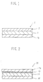
- Fig. 1 is a schematic sectional view showing an embodiment of the thermal transfer sheet according to the present invention.
- Fig. 2 is a schematic sectional view showing another embodiment of the thermal transfer sheet according to the present invention.
- Fig. 1 is a schematic sectional view showing an embodiment of the thermal transfer sheet according to the present invention.
- the thermal transfer sheet 1 comprises a substrate film 2, a back coating layer 3 formed on one surface side of the substrate film 2, and a recording material layer 4 formed on the other surface side of the substrate film 2.
- the above-mentioned back coating layer 3 is one capable of contacting a thermal head.
- the substrate film 2 to be used in the present invention may be one selected from those used in the conventional thermal transfer sheet.
- the above-mentioned substrate film 2 is not restricted thereto and can be any of other films.
- the substrate film 2 may include: plastic films such as those comprising polyester, polypropylene, cellophane, polycarbonate, cellulose acetate,polyethylene, polyvinyl chloride, polystyrene, nylon, polyimide, polyvinylidene chloride, polyvinyl alcohol, fluorine-cortaining resin, chlorinated rubber, and ionomer resin; papers such as capacitor paper and paraffin paper; non-woven fabric; etc.
- the substrate film 2 can also comprise a combination or laminate of the above-mentioned films.
- the substrate film 2 may preferably have a thickness of 0.5 to 50 ⁇ m, more preferably 3 to 10 ⁇ m, while the thickness can appropriately be changed corresponding to the materials thereof so as to provide suitable strength and heat conductivity.
- the back coating layer primarily characterising the present invention is formed on one surface side of the above-mentioned substrate film.
- the substrate film may preferably be one having a relatively high heat resistance such as polyethylene terephthalate film.
- the binder component of the back coating layer 3 predominantly comprises a styrene-acrylonitrile copolymer which may be obtained by co-polymerizing styrene and acrylonitrile. Such a copolymer may easily be prepared in an ordinary manner.
- any of commercially available products of various grades can be used in the present invention. Specific examples thereof may include those sold under the trade names of Sebian AD, Sebian LD, and Sebian NA (mfd. by Daiseru Kagaku K.K.).
- styrene-acrylonitrile copolymers of various grades it is preferred to use one having a molecular weight of 10 x 104 to 20 x 104 (more preferably 15 x 104 to 19 x 104), and/or an acrylonitrile content of 20 to 40 mol% (more preferably 25 to 30 mol%).
- Such a copolymer may preferably have a softening temperature of 400°C or higher according to differential thermal analysis, in view of heat resistance and dissolution stability to an organic solvent.
- the adhesion property between the above-mentioned styrene-acrylonitrile copolymer and the substrate film is not necessarily sufficient. Accordingly, in such a case, it is preferred to subject a monomer containing a small amount (e.g., several mol percent) of a functional group (such as methacrylic acid) to copolymerization, at the time of production of the styrene-acrylonitrile copolymer.
- a monomer containing a small amount (e.g., several mol percent) of a functional group (such as methacrylic acid) to copolymerization, at the time of production of the styrene-acrylonitrile copolymer.
- thermo transfer sheet having a back coating layer excellent in heat resistance, without troublesome heat treatment.
- a primer layer 13 is preliminarily formed on one surface side of a substrate film 12, a back coating layer 14 is then formed on the primer layer 13, and further a recording material layer 15 is formed on the other surface side of the substrate film 12, whereby a thermal transfer sheet 11 is obtained.
- the primer layer 13 may be formed by applying an adhesive resin onto the substrate film 12. Further, it is possible to use a small amount of such an adhesive resin in combination with the above-mentioned binder.
- the adhesive resin may preferably comprise an amorphous linear saturated polyester resin having a glass transition point of 50°C or higher.
- a polyester resin may include: those sold under trade names of Bairon (mfd. by Toyobo K.K.), Eriter (mfd. by Unitika K.K.), Polyester (mfd. by Nihon Gosei Kagaku K.K.). These resins of various grades are commercially available, and any of these resins can be used in the present invention.
- the primer layer In a case where the above-mentioned polyester resin is used for forming a primer layer, it is preferred to form the primer layer having a thickness of about 0.05 to 0.5 ⁇ m. If the thickness is too small, the resultant adhesive property may be insufficient. If the thickness is too large, sensitivity to a thermal head or heat resistance may undesirably be lowered.
- the adhesive resin e.g., polyester resin
- the adhesive resin content may preferably be 1 to 30 wt. parts per 100 wt. parts of the styrene-acrylonitrile copolymer. If the adhesive resin content is too low, the resultant adhesive property may be insufficient. If the adhesive resin content is too high, the heat resistance of the back coating layer may be lowered, or sticking may be caused.
- the back coating layer 3 comprising a binder predominantly comprising the styrene-acrylonitrile copolymer as described above also includes at least two species of heat-resistant particles having different particle sizes.
- the back coating layer 3 can also contain an optional additive.
- the heat-resistant particles used in the present invention may be as such known in the art. Specific examples thereof may include: Hydrotalsite DHT-4A (mfd. by Kyowa Kagaku Kogyo), Talcmicroace L-1 (mfd. by Nihon Talc), Taflon Rubron L-2 (mfd. by Daikin Kogyo), Fluorinated Graphite SCP-10 (mfd. by Sanpo Kagaku Kogyo), Graphite AT40S (mfd.
- heat-resistant particles those having various particle sizes are commercially available.
- a mixture of at least two species of heat-resistant particles having clearly different particle sizes is used.
- the particle sizes of these particles may preferably be selected corresponding to the thickness of the back coating layer to be formed.
- the back coating layer may preferably have a thickness of 0.1 to 0.5 ⁇ m
- the larger species of particle constituting the above-mentioned at least two species of heat-resistant particles may preferably have a particle size in the range of X/2 to X, wherein X denotes the thickness of the back coating layer.
- X denotes the thickness of the back coating layer.
- the particle size is smaller than 1 ⁇ 2 times the thickness of the back coating layer, resultant improvement in heat-resistance is insufficient.
- the particle size is larger than the thickness of the back coating layer, the formation of a back coating layer having a smooth surface is considerably obstructed, whereby a thermal head is liable to be worn.
- the smaller species of particle constituting the above-mentioned at least two species of heat-resistant particles may preferably have a particle size which is 1 ⁇ 2 times or smaller the particle size of the above-mentioned larger particles.
- the larger species of particle has a particle size of 0.3 ⁇ m
- the smaller species of particle may preferably have a particle size of 0.15 ⁇ m or smaller. If the smaller species of particle has a particle size exceeding such 0.15 ⁇ m, the particle size difference between the two species of particles is small, whereby it is difficult to fill the gaps between the larger particles with the smaller particles.
- the present invention is based on a discovery such that sufficient strength of a back coating layer may be maintained by using a combination of at least two species of heat-resistant particles having different particle sizes as described above, even when a relatively large amount of the heat-resistant particles are contained in the back coating layer.
- the larger species of heat-resistant particle has a function of imparting sufficient heat resistance to the back coating layer.
- the smaller species of heat-resistant particle has a function such that they fill gaps between the larger species of particle without decreasing the strength of the back coating layer, thereby to increase the heat-resistant particle content in the back coating layer and to further improve the heat-resistance of the back coating layer.
- the above-mentioned heat-resistant particles may preferably be used in an amount of 10 to 200 wt. parts with respect to 100 wt. parts of a binder. Further, the weight ratio between the larger and smaller species of particle may preferably be (20 to 80): (80 to 20). Outside these ranges of the amount and ratio to be used, good heat-resistance and strength of the back coating layer are not compatible with each other.
- a thermal release agent or lubricating agent may also be contained therein, within such an extent that the addition thereof does not substantially obstruct the achievement of the object of the present invention.
- a release agent or lubricating agent may include wax, higher fatty acid amide, ester, surfactant, and higher fatty acid metal salt.
- the larger species of particle imparts good heat resistance to the back coating layer and the smaller species of particle enhances the total amount of the filler.
- the back coating layer having good heat resistance and film strength by the synergistic effect based on the larger and smaller species of particles.
- the back coating layer may further comprise an alkylphosphate (or alkylphosphoric acid ester) multi-valent metal salt.
- the back coating layer can further contain an optional additive.
- the alkylphosphate multi-valent metal salt may be obtained by replacing the alkali metal of an alkylphosphate alkali metal salt with a multi-valent metal, and the alkylphosphate multi-valent metal salt per se is known as an additive for plastic in the art.
- Such multi-valent metal salts of various grades are commercially available, and any of these multi-valent metal salts can be used in the present invention.
- alkylphosphate multi-valent metal salt may include those represented by the following formula: and/or wherein R denotes an alkyl group having 12 or more carbon atoms such as cetyl, lauryl, and stearyl (particularly, stearyl); M denotes an alkaline earth metal such as barium, calcium and magnesium, and zinc, aluminum, etc.; and n denotes the valence of M .
- the above-mentioned alkylphosphate multi-valent metal salt in an amount of 10 to 150 wt. parts with respect to 100 wt. parts of the above-mentioned binder resin. If the amount of the multi-valent salt to be used is below the above range, sufficient slip property is difficult to be obtained. On the other hand, if the amount of the multi-valent salt exceeds the above range, the physical strength of the back coating layer may undesirably be lowered.
- a conductivity-imparting agent such as carbon black
- an antistatic agent such as quaternary ammonium salt and phosphate
- the back coating layer 3 may be formed by dissolving or dispersing the above-mentioned material in an appropriate solvent such as acetone, methyl ethyl ketone, toluene and xylene to prepare a coating liquid; and applying the coating liquid by an ordinary coating means such as gravure coater, roll coater, and wire bar; and drying the resultant coating.
- an appropriate solvent such as acetone, methyl ethyl ketone, toluene and xylene
- the coating amount of the back coating layer i.e., the thickness thereof, is also important.
- a back coating layer having sufficient performances may preferably be formed by using a coating amount of 0.5 g/m2 or below, more preferably 0.1 to 0.5 g/m2, based on the solid content thereof. If the back coating layer is too thick, the thermal sensitivity at the time of transfer operation may undesirably be lowered.
- the alkylphosphate multi-valent metal salt to be used in the present invention has a melting point of 150°C or higher, and further has a melting point of 200°C or higher in most cases, while it has an excellent slip property.
- a thermal transfer sheet which not only has an excellent heat resistance but also has an excellent slip property without contaminating another member (or object) or a thermal head, or wearing the thermal head.
- the recording material layer 4 may comprise an ink comprising a heat-fusible ink capable of being melted under heating and an optional mixed therewith.
- the heat-fusible ink used in the present invention comprises a colorant and a vehicle.
- the heat-fusible ink can also contain an optional additive selected from various species thereof, as desired.
- the colorant may preferably be one having a good recording property as a recording material, which is selected from organic or inorganic dyes or pigments.
- the colorant may preferably be one having a sufficient colouring density (or colouring power) and is not substantially faded due to light, heat, temperature, etc..
- the colorant can also comprise a substance such that it is colourless under no heating, or develops a colour when it contacts another substance which has been applied onto a transfer-receiving member.
- the colorant may be one capable of providing various colours in illusive of cyan, magenta, yellow, and black.
- the vehicle may predominantly comprise a wax or may comprise a mixture of a wax and another component such as drying oil, resin, mineral oil, and derivatives of cellulose and rubber.
- wax may include microcrystalline wax, carnauba wax, paraffin wax, etc.
- specific examples of the wax may include: various species thereof such as Fischer-Tropsch wax, various low-molecular weight polyethylene, Japan wax, beeswax, whale wax, insect wax, lanolin, shellac wax, candelilla wax, petrolactam, partially modified wax, fatty acid ester, and fatty acid amide.
- a heat-conducting substance can also be incorporated into the heat-fusible ink.
- a heat-conducting substance may include carbon substances such as carbon black, aluminum, copper, tin oxide, and molybdenum disulfide.
- a hot-melt coating material or a hot-lacquer coating material containing a solvent is prepared and such a coating material is applied by various means such as gravure coating, gravure reverse coating, gravure offset coating, roller coating and wire-bar coating.
- the thickness of the ink layer to be formed should be determined so that the requisite image density and thermal sensitivity are balanced with each other.
- the thickness may preferably be 0.1 to 30 ⁇ m, more preferably 2 to 10 ⁇ m.
- the surface layer constitutes a portion of a transferable film and has a function such that it forms a surface on one surface side contacting a transfer-receiving paper and sealing the printed portion of the transfer-receiving paper, and it prevents ground staining and enhances the adhesion property of the ink layer to the transfer-receiving paper.
- the surface layer may comprise a wax which is the same as that used in the above-mentioned heat-fusible ink layer.
- the surface layer comprising the wax may be formed by applying a liquid of melted wax and cooling the resultant coating; by applying a solution of the wax in an organic solvent and drying the resultant coating; by applying an aqueous dispersion containing particles of the wax and drying the resultant coating, etc..
- the surface layer may be formed by using various techniques in the same manner as in the formation of the ink layer.
- the surface layer may be selected so that the sensitivity does not become insufficient even in the case of a high-speed type printer using a low printing energy.
- the surface layer may preferably have a thickness which is not smaller than 0.1 ⁇ m and smaller than 5 ⁇ m.
- the printed letter obtained by thermal transfer method generally has a gloss and is beautiful, but in some cases, such a printed letter can decrease the readableness of the resultant document. Accordingly, dull printed images are sometimes preferred.
- a dispersion obtained by dispersing an inorganic pigment such as silica and calcium carbonate in appropriate resin and solvent is applied onto a substrate film to form thereon a matt layer, and then a heat-fusible ink is applied onto the matt layer; thereby to prepare a thermal transfer sheet, as proposed by our research group in Japanese Patent Application No. 208306/1983.
- the present invention is applicable to a thermal transfer sheet for colour printing. Accordingly, a multi-colour thermal transfer sheet is also within the scope of the present invention.
- the recording material layer 4 may comprise an ink comprising a sublimable (or heat-migrating) dye, and another material as desired.
- the dye used in the present invention may be any of dyes usable in the conventional thermal transfer sheet, and is not particularly restricted.
- Preferred examples of such a dye may include; red dyes such as MS Red G, Macrolex red Violet R, Ceres Red 7B, Samaron Red HBSL, Resolin Red F3BS; yellow dyes such as Horon Brilliant Yellow 6GL, PTY-52, Macrolex Yellow 6G; and blue dyes such as Kayaset Blue 714, Wacsorin Blue AP-FW, Horon Brilliant Blue S-R, and MS Blue 100.
- the binder for carrying the above-mentioned heat-migrating dye any of known binders can be used.
- Preferred examples of the binder resin may include: cellulose resins such as ethylcellulose, hydroxyethyl cellulose, ethylhydroxy-ethylcellulose, hydroxypropyl cellulose, methylcellulose, cellulose acetate, and cellulose acetate butyrate; vinyl-type resins such as polyvinyl alcohol, polyvinyl acetate, polyvinyl butyral, polyvinyl acetal, polyvinyl pyrrolidone, and polyacrylamide; and polyester resin.
- cellulose resins, acetal-type resins, butyral-type resins, and polyester-type resins are particularly preferred.
- the recording material layer can further contain an additive selected from those known in the prior art, as desired.
- the recording material layer 4 may preferably be formed by dissolving or dispersing the above-mentioned sublimable dye, binder resin and another optional components in an appropriate solvent to prepare a coating material or ink; applying the coating material or ink onto the above-mentioned substrate film; and drying the resultant coating.
- the thus formed recording material layer 4 may generally have a thickness of about 0.2 to 5.0 ⁇ m, preferably about 0.4 to 2.0 ⁇ m.
- the sublimable dye content in the recording material layer 4 may preferably be 5 to 90 wt.%, more preferably 10 to 70 wt.% based on the weight of the recording material layer.
- the back coating layer 3 may preferably contain a lubricating agent comprising alkylphosphate multi-valent metal salt.
- the alkylphosphate multi-valent metal salt to be used in the present invention has a melting point of 150°C or higher, and further has a melting point of 200°C or higher in most cases, while it has an excellent slipping property.
- a thermal transfer sheet having an excellent dye barrier property which not only has an excellent heat resistance, but also has an excellent slipping property without contaminating another member or a thermal head, or wearing the thermal head.
- the image-receiving sheet to be used for forming an image by use of the above-mentioned thermal transfer sheet containing a sublimable dye may be any of those having a recording surface having a dye receptibility to the above-mentioned dye.
- a sheet or film having no dye receptibility such as paper, metal, glass and synthetic resin
- a dye-receiving layer can also contain an optional additive within such an extent that the object of the present invention is not substantially obstructed.
- the additive may include: solid wax known as a release agent, such polyethylene wax, amide wax, and teflon powder; surfactant such as fluorine-containing surfactant and phosphoric ester-type surfactant.
- thermo printer e.g., Video Printer VY-100, mfd. by Hitachi Seisakusho K.K.
- the respective materials for the inks were mixed under stirring and subjected to dispersing treatment for three hours by means of a paint shaker.
- inks for recording material layer were prepared by using compositions shown in the following Table 7.
- the ink R-1 was a heat-fusible ink and was prepared by melt-kneading respective materials by means of a blade kneader at 100°C for 6 hours.
- the ink R-2 was a sublimable dye ink prepared at 50°C in a similar manner as described above.
- the inks for each coating layer were each applied onto their respective films in a coating amount (based on solid content) 0.2 grams per square metre (g/m2) or 0.5 grams per square metre (g/m2) by means of a wire bar coater, and the resultant coating was dried by hot air, thereby to form a back coating layer.
- the above-mentioned primer coating material was applied onto a polyethylene terephthalete film in a coating amount (based on solid content) of 0.2 grams per square metre (g/m2) by means of a wire bar coater, and then dried thereby to form a primer layer in advance. Thereafter, a back coating layer was formed onto the thus formed primer layer.
- the ink R-1 for recording material layer was heated at 100°C and applied onto the surface of the substrate film reverse to the surface thereof provided with the above-mentioned back coating layer, by a hot-melt roller coating method in a coating amount of about 5.0 grams per square metre (g/m2), thereby to form a recording material layer.
- the ink R-2 for recording material layer was applied onto the surface of the substrate film reverse to the surface thereof provided with the above-mentioned back coating layer, by means of a wire bar in a coating amount of 2.0 grams per square metre (g/m2) (after drying), and then dried, thereby to form a recording material layer.
- the test was conducted under the above-mentioned respective conditions. With respect to the Samples 1 to 5, 7 and 8, plain paper was used for printing. With respect to the Samples 6 and 9, printing was effected on an image-receiving sheet for thermal transfer instead of the plain paper.
- Polyester (Bairon 103, mfd. by Toyo Boseki K.K.) 8.0 parts Polymer plasticizer (Erubaroi 741P, mfd. by Mitsui Polychemical K.K.) 2.0 parts Amino-modified silicone oil (KF-393, mfd. by Shinetsu Silicone K.K.) 0.125 parts Epoxy-modified silicone oil (X-22-343, mfd by Shinetsu silicone K.K.) 0.125 parts Toluene 70.0 parts Methyl ethyl ketone 10.0 parts Cyclohexanone 20.0 parts
- Static characteristic was evaluated by using a device for test as a current-conduction time of 6ms. The results are shown in Table 8 appearing hereinafter according to the following evaluation standards.
- Heat-wiping test under heating was conducted by using a calender roller.
- the back coating loyer was caused to contact the roller surface and the peeling of the back coating layer was evaluated under the above-mentioned conditions. The results are shown in Table 8 appearing hereinafter.
Landscapes
- Physics & Mathematics (AREA)
- Optics & Photonics (AREA)
- Thermal Transfer Or Thermal Recording In General (AREA)
Claims (12)
- Thermotransferflachmaterial mit einem Substratfilm, einer Aufzeichnungs-Materialschicht, die auf einer Oberflächenseite des Substratfilms gebildet ist, und einer hinteren Beschichtungsschicht, die auf der anderen Oberflächenseite des Substratfilms gebildet ist, um in Kontakt mit einem Thermokopf zu stehen, wobei die Aufzeichnungs-Materialschicht eine wärmeschmelzbare Farbe, die durch Erwärmen geschmolzen werden kann, oder einen Farbstoff und Bindemittel aufweist, dadurch gekennzeichnet, daß die hintere Beschichtungsschicht ein Bindemittel aufweist, das hauptsächlich ein Styrol-Acrylnitril-Copolymer und mindestens zwei Arten von hitzeresistenten Teilchen mit unterschiedlichen Partikelgrößen aufweist.
- Flachmaterial nach Anspruch 1, dadurch gekennzeichnet, daß die hintere Beschichtungsschicht weiterhin ein mehrwertiges Alkylphosphat-Metallsalz aufweist.
- Flachmaterial nach Anspruch 1 oder 2, dadurch gekennzeichnet, daß das Styrol-Acrylnitril-Copolymer ein Acrylnitril-Copolymerisations-Verhältnis von 20 bis 40 Mol% hat.
- Flachmaterial nach einem der Ansprüche 1 bis 3, dadurch gekennzeichnet, daß das Styrol-Acrylnitril-Copolymer ein Molekulargewicht von 10 x 10⁴ bis 20 x 10⁴ hat.
- Flachmaterial nach einem der Ansprüche 1 bis 4, dadurch gekennzeichnet, daß die hintere Beschichtungsschicht ein lineares Polyesterharz als ein darin vermischtes Klebeharz enthält.
- Flachmaterial nach einem der Ansprüche 1 bis 5, dadurch gekennzeichnet, daß eine ein Klebeharz aufweisende Grundierungsschicht zwischen dem Substratfilm und der hinteren Beschichtungsschicht vorhanden ist.
- Flachmaterial nach einem der Ansprüche 1 bis 6, dadurch gekennzeichnet, daß die mindestens zwei Arten von hitzeresistenten Teilchen eine größere Art von Teilchen und eine kleinere Art von Teilchen umfassen, wobei die größere Art von Teilchen eine Partikelgröße von 1/2 X bis X hat, wobei X die Dicke der hinteren Beschichtungsschicht darstellt; wobei die kleinere Art von Teilchen eine Partikelgröße hat, die 1/2 mal so groß wie die Partikelgröße der größeren hitzeresistenten Teilchen oder kleiner ist.
- Flachmaterial nach einem der Ansprüche 1 bis 7, dadurch gekennzeichnet, daß die gesamte Menge der hitzeresistenten Teilchen 10 bis 200 Gewichtsteile in bezug auf 100 Gewichtsteile des Bindemittels beträgt.
- Flachmaterial nach einem der Ansprüche 1 bis 8, dadurch gekennzeichnet, daß das Verhältnis zwischen dem Gewicht, das für die größere Teilchenart verwendet wird und dem der kleineren Teilchenart (20 bis 80)/(80 bis 20) beträgt.
- Flachmaterial nach einem der Ansprüche 1 bis 9, dadurch gekennzeichnet, daß die hintere Beschichtungsschicht eine Dicke von 0,1 bis 0,5µm hat.
- Flachmaterial nach einem der Ansprüche 2 bis 10, dadurch gekennzeichnet, daß das mehrwertige Alkylphosphat-Metallsalz eine Verbindung ist, die durch die folgende Formeln dargestellt ist:


- Flachmaterial nach einem der Ansprüche 2 bis 11, dadurch gekennzeichnet, daß das mehrwertige Alkylphophat-Metallsalz in der hinteren Beschichtungsschicht in einer Menge von 10 bis 150 Gewichtsteilen in bezug auf 100 Gewichtsteile des Bindemittels enthalten ist.
Priority Applications (1)
| Application Number | Priority Date | Filing Date | Title |
|---|---|---|---|
| EP95106869A EP0672543B1 (de) | 1989-07-07 | 1990-07-06 | Thermisches Übertragungsblatt |
Applications Claiming Priority (4)
| Application Number | Priority Date | Filing Date | Title |
|---|---|---|---|
| JP1176538A JP2792603B2 (ja) | 1989-07-07 | 1989-07-07 | 熱転写シート |
| JP1176537A JP2904814B2 (ja) | 1989-07-07 | 1989-07-07 | 熱転写シート |
| JP176537/89 | 1989-07-07 | ||
| JP176538/89 | 1989-07-07 |
Related Child Applications (2)
| Application Number | Title | Priority Date | Filing Date |
|---|---|---|---|
| EP95106869.1 Division-Into | 1990-07-06 | ||
| EP95106869A Division EP0672543B1 (de) | 1989-07-07 | 1990-07-06 | Thermisches Übertragungsblatt |
Publications (3)
| Publication Number | Publication Date |
|---|---|
| EP0407220A2 EP0407220A2 (de) | 1991-01-09 |
| EP0407220A3 EP0407220A3 (en) | 1991-08-21 |
| EP0407220B1 true EP0407220B1 (de) | 1996-03-06 |
Family
ID=26497413
Family Applications (2)
| Application Number | Title | Priority Date | Filing Date |
|---|---|---|---|
| EP90307433A Expired - Lifetime EP0407220B1 (de) | 1989-07-07 | 1990-07-06 | Thermisches Übertragungsblatt |
| EP95106869A Expired - Lifetime EP0672543B1 (de) | 1989-07-07 | 1990-07-06 | Thermisches Übertragungsblatt |
Family Applications After (1)
| Application Number | Title | Priority Date | Filing Date |
|---|---|---|---|
| EP95106869A Expired - Lifetime EP0672543B1 (de) | 1989-07-07 | 1990-07-06 | Thermisches Übertragungsblatt |
Country Status (4)
| Country | Link |
|---|---|
| US (1) | US5260127A (de) |
| EP (2) | EP0407220B1 (de) |
| CA (1) | CA2020619C (de) |
| DE (2) | DE69032794T2 (de) |
Families Citing this family (11)
| Publication number | Priority date | Publication date | Assignee | Title |
|---|---|---|---|---|
| US5593940A (en) * | 1989-07-07 | 1997-01-14 | Dai Nippon Insatsu Kabushiki Kaisha | Thermal transfer sheet |
| US5096875A (en) * | 1990-06-28 | 1992-03-17 | Eastman Kodak Company | Thermal dye transfer receiving element with backing layer |
| US5162292A (en) * | 1991-05-06 | 1992-11-10 | Eastman Kodak Company | Slipping layer containing a phosphonic acid derivative for dye-donor element used in thermal dye transfer |
| EP0527520A1 (de) * | 1991-08-13 | 1993-02-17 | Agfa-Gevaert N.V. | Farbstoffgebendes Element für thermische Farbstoffübertragung durch Sublimation |
| US5459120A (en) * | 1993-06-09 | 1995-10-17 | Agfa-Gevaert, N.V. | Heat-resistant layer for dye-donor element |
| DE69305159T2 (de) * | 1993-07-12 | 1997-04-10 | Agfa Gevaert Nv | Farbstoffdonorelement zur Anwendung in einem thermischen Farbstoffübertragungsverfahren |
| US5559077A (en) * | 1994-09-26 | 1996-09-24 | Eastman Kodak Company | Antistatic backing layer for transparent receiver used in thermal dye transfer |
| US5932643A (en) * | 1997-04-11 | 1999-08-03 | Ncr Corporation | Thermal transfer ribbon with conductive polymers |
| JP2000339895A (ja) * | 1999-03-24 | 2000-12-08 | Nitto Denko Corp | 制振材およびそれを用いたヘッドサスペンション |
| US20050137291A1 (en) * | 2003-12-17 | 2005-06-23 | Schneider John R. | Coating compositions with enhanced corrosion resistance and appearance |
| CN102381069B (zh) * | 2011-08-10 | 2015-02-11 | 福州艾瑞数码影像有限公司 | 喷墨或激光两用打印热转印纸 |
Family Cites Families (13)
| Publication number | Priority date | Publication date | Assignee | Title |
|---|---|---|---|---|
| US4720480A (en) * | 1985-02-28 | 1988-01-19 | Dai Nippon Insatsu Kabushiki Kaisha | Sheet for heat transference |
| JPS5926632B2 (ja) * | 1976-12-18 | 1984-06-29 | 堺化学工業株式会社 | 有機りん化合物の製造法 |
| JPS5936880B2 (ja) * | 1979-07-31 | 1984-09-06 | 富士通株式会社 | 熱転写記録方法 |
| US4567113A (en) * | 1983-09-12 | 1986-01-28 | General Company Limited | Heat-sensitive transferring recording medium |
| CA1228728A (en) * | 1983-09-28 | 1987-11-03 | Akihiro Imai | Color sheets for thermal transfer printing |
| JPS60250989A (ja) * | 1984-05-29 | 1985-12-11 | Pilot Pen Co Ltd:The | 感熱転写リボン |
| JPS62292484A (ja) * | 1986-06-11 | 1987-12-19 | Diafoil Co Ltd | 感熱転写フイルム |
| JPS639574A (ja) * | 1986-07-01 | 1988-01-16 | Dainippon Printing Co Ltd | 熱転写シ−ト |
| US4925735A (en) * | 1986-07-29 | 1990-05-15 | Konishiroku Photo Industry Co., Ltd. | Resin composition for heat-sensitive transfer recording medium and heat-sensitive transfer recording medium |
| US4727057A (en) * | 1986-10-27 | 1988-02-23 | Eastman Kodak Company | Polyester subbing layer for slipping layer of dye-donor element used in thermal dye transfer |
| JPS641586A (en) * | 1987-03-02 | 1989-01-05 | Konica Corp | Thermal transfer recording medium |
| JPS645884A (en) * | 1987-06-29 | 1989-01-10 | Dainippon Printing Co Ltd | Thermal transfer sheet |
| JPH01141794A (ja) * | 1987-11-30 | 1989-06-02 | Matsushita Electric Ind Co Ltd | 発熱体 |
-
1990
- 1990-07-05 US US07/548,094 patent/US5260127A/en not_active Expired - Lifetime
- 1990-07-06 DE DE69032794T patent/DE69032794T2/de not_active Expired - Lifetime
- 1990-07-06 EP EP90307433A patent/EP0407220B1/de not_active Expired - Lifetime
- 1990-07-06 DE DE69025661T patent/DE69025661T2/de not_active Expired - Lifetime
- 1990-07-06 CA CA002020619A patent/CA2020619C/en not_active Expired - Lifetime
- 1990-07-06 EP EP95106869A patent/EP0672543B1/de not_active Expired - Lifetime
Also Published As
| Publication number | Publication date |
|---|---|
| CA2020619C (en) | 1996-07-16 |
| CA2020619A1 (en) | 1991-01-08 |
| EP0672543B1 (de) | 1998-11-25 |
| EP0407220A3 (en) | 1991-08-21 |
| US5260127A (en) | 1993-11-09 |
| DE69032794D1 (de) | 1999-01-07 |
| DE69032794T2 (de) | 1999-08-05 |
| EP0407220A2 (de) | 1991-01-09 |
| DE69025661T2 (de) | 1996-11-21 |
| EP0672543A1 (de) | 1995-09-20 |
| DE69025661D1 (de) | 1996-04-11 |
Similar Documents
| Publication | Publication Date | Title |
|---|---|---|
| EP0333873B1 (de) | Wärmeübertragungsblatt | |
| JP3585598B2 (ja) | 熱転写シート | |
| EP0625429B1 (de) | Thermische Übertragungsschicht | |
| CA2047981C (en) | Receptor layer transfer sheet, thermal transfer sheet, thermal transfer method and apparatus therefor | |
| CA1225524A (en) | Heat transfer printing sheet | |
| EP0411924B1 (de) | Thermische Übertragungsschicht | |
| EP0407220B1 (de) | Thermisches Übertragungsblatt | |
| EP1316437B1 (de) | Verfahren zur Bilderzeugung und Produkt mit darauf erzeugtem Bild | |
| US5593940A (en) | Thermal transfer sheet | |
| EP1136279B1 (de) | Polyamidimidharzrückseitenbeschichtung enthaltendes thermisches Übertragungsblatt | |
| JP3033829B2 (ja) | 熱転写シート | |
| EP0683058A1 (de) | Wärmeempfindliches Übertragungsblatt zum Drucken eines Weiss-Bildes | |
| JP2967538B2 (ja) | 熱転写シート及びカードの製造方法 | |
| JPH0630969B2 (ja) | 感熱転写シート | |
| JP3114977B2 (ja) | 熱転写シート | |
| JP2792603B2 (ja) | 熱転写シート | |
| EP1736322A2 (de) | Thermisches Übertragungsblatt. | |
| JP2895492B2 (ja) | 熱転写シート | |
| JP2925944B2 (ja) | 被熱転写シート | |
| JPH0342286A (ja) | 熱転写シート | |
| JPH02251485A (ja) | 多数回印字用熱転写シート | |
| JPH04142985A (ja) | 画像形成方法及び複合熱転写シート |
Legal Events
| Date | Code | Title | Description |
|---|---|---|---|
| PUAI | Public reference made under article 153(3) epc to a published international application that has entered the european phase |
Free format text: ORIGINAL CODE: 0009012 |
|
| AK | Designated contracting states |
Kind code of ref document: A2 Designated state(s): DE FR GB IT NL |
|
| 17P | Request for examination filed |
Effective date: 19901219 |
|
| PUAL | Search report despatched |
Free format text: ORIGINAL CODE: 0009013 |
|
| AK | Designated contracting states |
Kind code of ref document: A3 Designated state(s): DE FR GB IT NL |
|
| 17Q | First examination report despatched |
Effective date: 19931124 |
|
| GRAA | (expected) grant |
Free format text: ORIGINAL CODE: 0009210 |
|
| AK | Designated contracting states |
Kind code of ref document: B1 Designated state(s): DE FR GB IT NL |
|
| XX | Miscellaneous (additional remarks) |
Free format text: TEILANMELDUNG 95106869.1. |
|
| ITF | It: translation for a ep patent filed | ||
| REF | Corresponds to: |
Ref document number: 69025661 Country of ref document: DE Date of ref document: 19960411 |
|
| ET | Fr: translation filed | ||
| PLBE | No opposition filed within time limit |
Free format text: ORIGINAL CODE: 0009261 |
|
| STAA | Information on the status of an ep patent application or granted ep patent |
Free format text: STATUS: NO OPPOSITION FILED WITHIN TIME LIMIT |
|
| 26N | No opposition filed | ||
| REG | Reference to a national code |
Ref country code: GB Ref legal event code: IF02 |
|
| PGFP | Annual fee paid to national office [announced via postgrant information from national office to epo] |
Ref country code: FR Payment date: 20090617 Year of fee payment: 20 |
|
| PGFP | Annual fee paid to national office [announced via postgrant information from national office to epo] |
Ref country code: NL Payment date: 20090623 Year of fee payment: 20 Ref country code: GB Payment date: 20090707 Year of fee payment: 20 Ref country code: DE Payment date: 20090824 Year of fee payment: 20 |
|
| PGFP | Annual fee paid to national office [announced via postgrant information from national office to epo] |
Ref country code: IT Payment date: 20090721 Year of fee payment: 20 |
|
| REG | Reference to a national code |
Ref country code: NL Ref legal event code: V4 Effective date: 20100706 |
|
| REG | Reference to a national code |
Ref country code: GB Ref legal event code: PE20 Expiry date: 20100705 |
|
| PG25 | Lapsed in a contracting state [announced via postgrant information from national office to epo] |
Ref country code: NL Free format text: LAPSE BECAUSE OF EXPIRATION OF PROTECTION Effective date: 20100706 |
|
| PG25 | Lapsed in a contracting state [announced via postgrant information from national office to epo] |
Ref country code: GB Free format text: LAPSE BECAUSE OF EXPIRATION OF PROTECTION Effective date: 20100705 |
|
| PG25 | Lapsed in a contracting state [announced via postgrant information from national office to epo] |
Ref country code: DE Free format text: LAPSE BECAUSE OF EXPIRATION OF PROTECTION Effective date: 20100706 |