EP0409175A2 - Aufzeichnungsvorrichtung - Google Patents
Aufzeichnungsvorrichtung Download PDFInfo
- Publication number
- EP0409175A2 EP0409175A2 EP90113692A EP90113692A EP0409175A2 EP 0409175 A2 EP0409175 A2 EP 0409175A2 EP 90113692 A EP90113692 A EP 90113692A EP 90113692 A EP90113692 A EP 90113692A EP 0409175 A2 EP0409175 A2 EP 0409175A2
- Authority
- EP
- European Patent Office
- Prior art keywords
- stepping motor
- control
- motor
- carriage
- speed
- Prior art date
- Legal status (The legal status is an assumption and is not a legal conclusion. Google has not performed a legal analysis and makes no representation as to the accuracy of the status listed.)
- Granted
Links
- 238000001514 detection method Methods 0.000 abstract description 5
- 238000000034 method Methods 0.000 description 7
- 230000000875 corresponding effect Effects 0.000 description 6
- 230000001276 controlling effect Effects 0.000 description 5
- 238000012545 processing Methods 0.000 description 5
- 238000010586 diagram Methods 0.000 description 3
- 230000004044 response Effects 0.000 description 3
- 230000007246 mechanism Effects 0.000 description 2
- 230000000630 rising effect Effects 0.000 description 2
- 230000032683 aging Effects 0.000 description 1
- 238000010276 construction Methods 0.000 description 1
- 230000008602 contraction Effects 0.000 description 1
- 230000000694 effects Effects 0.000 description 1
- 230000007613 environmental effect Effects 0.000 description 1
- 230000012447 hatching Effects 0.000 description 1
- 230000020169 heat generation Effects 0.000 description 1
- 239000010687 lubricating oil Substances 0.000 description 1
- 239000000463 material Substances 0.000 description 1
- 230000003287 optical effect Effects 0.000 description 1
- 239000002245 particle Substances 0.000 description 1
- 230000002250 progressing effect Effects 0.000 description 1
- 229920006395 saturated elastomer Polymers 0.000 description 1
- 238000004804 winding Methods 0.000 description 1
Images




Classifications
-
- B—PERFORMING OPERATIONS; TRANSPORTING
- B41—PRINTING; LINING MACHINES; TYPEWRITERS; STAMPS
- B41J—TYPEWRITERS; SELECTIVE PRINTING MECHANISMS, i.e. MECHANISMS PRINTING OTHERWISE THAN FROM A FORME; CORRECTION OF TYPOGRAPHICAL ERRORS
- B41J29/00—Details of, or accessories for, typewriters or selective printing mechanisms not otherwise provided for
- B41J29/38—Drives, motors, controls or automatic cut-off devices for the entire printing mechanism
-
- B—PERFORMING OPERATIONS; TRANSPORTING
- B41—PRINTING; LINING MACHINES; TYPEWRITERS; STAMPS
- B41J—TYPEWRITERS; SELECTIVE PRINTING MECHANISMS, i.e. MECHANISMS PRINTING OTHERWISE THAN FROM A FORME; CORRECTION OF TYPOGRAPHICAL ERRORS
- B41J19/00—Character- or line-spacing mechanisms
- B41J19/18—Character-spacing or back-spacing mechanisms; Carriage return or release devices therefor
- B41J19/20—Positive-feed character-spacing mechanisms
- B41J19/202—Drive control means for carriage movement
-
- Y—GENERAL TAGGING OF NEW TECHNOLOGICAL DEVELOPMENTS; GENERAL TAGGING OF CROSS-SECTIONAL TECHNOLOGIES SPANNING OVER SEVERAL SECTIONS OF THE IPC; TECHNICAL SUBJECTS COVERED BY FORMER USPC CROSS-REFERENCE ART COLLECTIONS [XRACs] AND DIGESTS
- Y10—TECHNICAL SUBJECTS COVERED BY FORMER USPC
- Y10S—TECHNICAL SUBJECTS COVERED BY FORMER USPC CROSS-REFERENCE ART COLLECTIONS [XRACs] AND DIGESTS
- Y10S400/00—Typewriting machines
- Y10S400/903—Stepping-motor drive for carriage feed
Definitions
- the present invention relates to a recording apparatus and, more particularly, to a serial type recording apparatus in which a stepping motor is used as a driving source for effecting at least the movement for the recording and scanning of a recording head.
- a stepping motor or a brushless motor of the hybrid type or the PN (permanent magnet) type is frequently used as a motor to drive a carriage for conveying a recording head in order to record and scan.
- a Hall element is ordinarily used to detect the position of the magnetic pole of a rotor to control a current supply.
- An optical or magnetical type encoder is used to detect the speed of the rotor.
- the driving control of the stepping motor has been executed by easily open loop controlling the frequency of the pulses of the same number as the number of driving pulses of the stepping motor.
- an encoder is attached to the rotary shaft of the stepping motor, an output signal of the encoder is counted, the rotational position is detected, and a motor energization signal is switched when the count value coincides with a predetermined count value, thereby controlling the rotation of the stepping motor.
- the load torque increases in the following cases. For instance, under a low temperature environment, a viscosity of lubricating oil for reducing the friction which was coated onto the carriage sliding shaft deteriorates, or coefficients of thermal contraction are not matched due to a difference of materials of the parts, or paper particles, dusts, and the like enter between the sliding shaft and the carriage, so that a friction load increases and the load torque of the motor is increased.
- a load torque margin is provided so that the normal operation can be also executed even if the driving system changed.
- the number of parts increases, the costs rise, and the like.
- Another object of the Invention is to enable the optimum driving state to be always obtained by changing an output torque characteristic in accordance with a motor load.
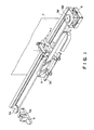
- Fig. 1 shows a carriage driving mechanism.
- Reference numeral 1 denotes a recording head of, for example, the ink jet type; 2 a carriage on which the recording head 1 is mounted and which moves along guide shafts 3A and 3B; 4 a timing belt whose both ends are coupled to the carriage 2 and which is reeved between pulleys 5A and 5B; 6 a carriage driving motor to drive the carriage 2 through the timing belt 4; and 7 a recording sheet which is held at the opposite position of the recording head 1 by a platen or the like (not shown).
- a shielding plate 8 is attached to the carriage 2.
- the shielding plate 8 is inserted into a slit 9A of a photo sensor 9.
- an encoder (not shown) attached coaxially with the carriage driving motor 6 is initialized as "0".
- the carriage 2 is moved from the initial position in the F direction, namely, to the right, the position is successively detected by counting the signal from the encoder and, at the same time, the recording is executed onto the recording sheet 7.
- the recording sheet 7 is fed by an amount corresponding to only one line by sheet feeding means (not shown).
- a rotational speed of the motor 1 corresponding to such a recording desity is set to about 800 r.p.m. in the high speed mode and is set to about 400 r.p.m. in the low speed mode.
- a time which is required from the start of the carriage until the arrival at a constant speed running (rotational speed: 800 r.p.m.) in the high speed mode is set to about 60 msec
- a constant speed running time is set to about one second
- a time which is required from the constant speed run until the stop of the carriage is set to about 60 msec.
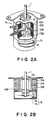
- Figs. 2A and 2B show an example of a construction of the carriage driving motor 6 mentioned above.
- Reference numeral 10 denotes a rotor; 11 a rotor shaft; 12A and 12B stators arranged around the rotor 10; and 13A and 13B coils.
- a detecting disk 14 of the encoder is attached coaxially to the rotor shaft 11.
- a photo interrupter 15 is attached on the stator side. Therefore, the rotational position of the motor 6 can be detected by counting output pulses from a rotary encoder 16 comprising the detecting disk 14 and the photo interrupter 15.
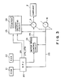
- a motor drive control system to execute a closed loop control of the carriage driving motor 6 will now be described with reference to Figs. 3 and 4.
- reference numeral 20 denotes an MPU (microprocessor unit) to control the whole recording apparatus.
- the MPU 20 drives and controls driving sources of the other mechanisms (not shown) by using an RAM (random access memory) 22 for processing recording data and also controls the carriage driving motor 6 to drive the carriage 2.
- the MPU 20 has a counter constructed by a hardware or software (not shown) and detects the position of the carriage 2 by counting output pulses 23 from the rotary encoder 16.
- the MPU 20 controls the rotational speed of the carriage driving motor 6 to foregoing speed in the high or low speed mode through a motor speed control circuit 24.
- the MPU 20 controls the start, stop, and rotating direction of the carriage driving motor 6 through a current switching circuit 25 for switching energization currents to the coils 13A and 13B of the motor 6, thereby starting, stopping, and moving the carriage 2.
- the motor speed control circuit 24 closed-loop controls the rotational speed of the motor 6 in accordance with a detection output of the encoder 16. Practically speaking, a time interval between the output pulses 23 from the encoder 16 is compared with a preset reference time. In accordance with the result of the comparison, a control output 26 to the motor 6 is adjusted so as to eliminate the time difference.
- the motor speed control circuit 24 selects the comparing reference time corresponding to the instructed speed in response to such a speed instruction and compares the reference time with the pulse interval, thereby controlling the rotational speed of the motor 6 to the speed in the high or low speed modes.
- the current switching circuit 25 starts the switching operation of the energization currents by a start signal 27A which is input from the MPU 20, thereby starting the motor 6.
- the motor 6 is stopped by a stop signal 27B which is input from the MPU 20.
- the current switching circuit 25 controls the switching timing of the coil energization currents of the carriage driving motor 6 by a closed loop in response to the detection output of the encoder 16 in accordance with a procedure, which will be explained hereinlater, by the MPU 20.
- the current switching circuit 25 has a counter 28. The output pulses from the encoder 16 are counted by the counter 28 and the energization currents are switched at a time point when the count value coincides with a predetermined value.
- the energization currents are switched 48 times per rotation of the rotor by a pattern of a single phase.
- the motor 6 since the motor 6 is not rotated unless a predetermined relative positional relation is held between the magnetic pole of the rotor and the magnetic poles of the stators 12A and 12B, it is necessary to match the relative positions between the magnetic pole of the rotor and the magnetic poles of the stators as an initial operation. Therefore, actually, in a state in which a predetermined phase was energized, the counter 28 in the current switching circuit 25 is reset to a predetermined numerical value. After that, the pulses from the encoder 16 are counted by the counter 28 and the energization currents are switched every other predetermined value (six pulses in the case of the embodiment).
- the energization currents can be switched.
- a ring counter which can count 24 pulses of one torque cycle, that is, four steps is used as a counter 28. Assuming that the count values for switching of the energization in this case are set to 6, 12, 18, and 0, energization waveforms as shown in Fig. 5A are obtained.
- step S1 a check is made to see if the difference between the actual rotational speed and the instructed speed from the MPU 20 is 0 or not. If it is not 0, step S2 follows and a control output corresponding to the difference is calculated. In the next step S3, a check is made to see if the control output has exceeded an 80% output or not. If NO, step S4 follows and the motor 6 is driven by the control output. If it has exceeded the 80% output in step S3, the processing routine advances to step S5 and the energization switching value is changed and the processing routine is returned to step S1.
- the energization switching value of the counter 28 in the current switching circuit 28 is corrected by only 1 in the direction reverse to the direction of the count by a phase advance signal 29.
- the count value of the counter 28 is increased, the energization waveforms are as shown in Fig. 5B.
- the phase of the energization current switching signal is advanced, so that a current can easily flow in the winding.
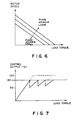
- Fig. 6 shows a change in output torque characteristic of the motor in the case where the phase of the energization signal was advanced. As will be understood from Fig.
- the motor 6 since the output torque of the motor 6 increases as the switching phase is advanced, the motor 6 can be also controlled to a predetermined speed even for a load in a wide range. Therefore, even in the case where the load torque increases and the output becomes maximum and exceeds the speed control limit, by advancing the phase, the output torque can be raised and the speed control can be properly executed. A situation such that when the control output arrived at 100%, the motor becomes uncontrollable as in the conventional apparatus does not occur.
- Fig. 7 shows the relation between the load torque and the output of the control circuit.
- the control output also increases in proportion to an increase in load torque and, finally, the control output is saturated as shown by a broken line.
- the phase for energization switching is advanced, so that the output value is suppressed to a low value as shown by a solid line and, thereafter, the output value similarly increases in proportion to the load.
- the output can be controlled to a predetermined value or less.
- the reason why the output characteristics of the motor 6 have been switched in accordance with the load of the motor 6 is because the optimum values of the various constants (for instance, loop gain and phase) for the speed control differ depending on the output characteristics of the motor and the load state.
- the various constants for instance, loop gain and phase
- control output value for the load of the motor 6 is also likewise traced and examined. However, if the control output value has exceeded a certain limit value (for instance, 80% of the maximum output), the power source voltage is increased. A control procedure in the above case is shown in Fig. 8.
- the power source voltage in such a case can be switched by a transistor or the like (not shown).
- step S4 Since the procedure for the control operation from step S1 to step S4 is similar to that in the case of Fig. 4, its description is omitted. If the control output has exceeded the 80% output in step S3, the processing routine advances to step S5 and the driving power source is raised as mentioned above. Then, the processing routine is returned to step S1.
- the carriage driving motor is closed-loop controlled so as to optimize the output torque characteristics of the motor in accordance with a change in load of the motor, a stable control of a high reliability can be connected, and the high speed recording of a low noise can be executed.
- a recording apparatus in which a stepping motor is used as a driving source to reciprocate a carriage on which a recording head is mounted and the recording is executed by the recording head in accordance with the timing when the stepping motor rotates, comprising: a rotational position detector to detect a rotational position of the stepping motor; a current switching circuit to switch energization currents to the stepping motor on the basis of a detection signal from the rotational position detector; a motor speed control circuit to closed loop control a rotational speed of the stepping motor through the current switching circuit; and a controller for detecting a load corresponding to the stepping motor by a speed control output from the motor speed control circuit and for controlling so as to change output torque characteristics of the stepping motor in accordance with the load.
Landscapes
- Control Of Stepping Motors (AREA)
- Character Spaces And Line Spaces In Printers (AREA)
Applications Claiming Priority (2)
| Application Number | Priority Date | Filing Date | Title |
|---|---|---|---|
| JP183742/89 | 1989-07-18 | ||
| JP1183742A JPH0798414B2 (ja) | 1989-07-18 | 1989-07-18 | 記録装置 |
Publications (3)
| Publication Number | Publication Date |
|---|---|
| EP0409175A2 true EP0409175A2 (de) | 1991-01-23 |
| EP0409175A3 EP0409175A3 (en) | 1991-08-14 |
| EP0409175B1 EP0409175B1 (de) | 1996-10-09 |
Family
ID=16141183
Family Applications (1)
| Application Number | Title | Priority Date | Filing Date |
|---|---|---|---|
| EP90113692A Expired - Lifetime EP0409175B1 (de) | 1989-07-18 | 1990-07-17 | Aufzeichnungsvorrichtung |
Country Status (4)
| Country | Link |
|---|---|
| US (1) | US5097189A (de) |
| EP (1) | EP0409175B1 (de) |
| JP (1) | JPH0798414B2 (de) |
| DE (1) | DE69028816T2 (de) |
Cited By (2)
| Publication number | Priority date | Publication date | Assignee | Title |
|---|---|---|---|---|
| EP0482356A3 (en) * | 1990-09-21 | 1992-08-05 | Canon Kabushiki Kaisha | Recording apparatus |
| EP0834405A3 (de) * | 1996-10-03 | 1999-08-04 | Canon Kabushiki Kaisha | Aufzeichnungsgerät |
Families Citing this family (17)
| Publication number | Priority date | Publication date | Assignee | Title |
|---|---|---|---|---|
| US5467173A (en) * | 1993-02-05 | 1995-11-14 | Konica Corporation | Speed control circuit for an optical scanning system driving motor for an image forming apparatus |
| JPH07195784A (ja) * | 1993-12-28 | 1995-08-01 | Canon Inc | プリンタの駆動方法 |
| KR100316280B1 (ko) * | 1995-03-10 | 2002-04-24 | 무라타 기카이 가부시키가이샤 | 스텝모터의제어방법 |
| EP0748038B1 (de) * | 1995-06-05 | 2002-08-21 | Kollmorgen Corporation | System und Verfahren zur Steuerung von bürstenlosen Permanentmagnetmotoren |
| TW492944B (en) * | 1997-03-20 | 2002-07-01 | Barmag Barmer Maschf | Traversing device and method for controlling a traversing device |
| US6174037B1 (en) * | 1997-06-02 | 2001-01-16 | Xerox Corporation | Multiple pass ink jet printer with optimized power supply |
| JPH11147322A (ja) * | 1997-08-29 | 1999-06-02 | Seiko Epson Corp | プリンタ |
| US6078158A (en) * | 1998-12-04 | 2000-06-20 | International Business Machines Corporation | Disk drive motor spin-up control |
| US6322184B1 (en) * | 1999-05-10 | 2001-11-27 | Hewlett-Packard Company | Method and apparatus for improved swath-to-swath alignment in an inkjet print engine device |
| US7342690B2 (en) * | 2003-03-17 | 2008-03-11 | Kabushiki Kaisha Toshiba | Method and apparatus for reading image |
| US20050199140A1 (en) * | 2004-02-27 | 2005-09-15 | Ho Wai Y. | Automatic transmission system for a printer carriage drive |
| US7106020B1 (en) | 2005-08-30 | 2006-09-12 | Honeywell International Inc. | Method of operating a brushless DC motor |
| US7265512B2 (en) | 2005-08-30 | 2007-09-04 | Honeywell International Inc. | Actuator with feedback for end stop positioning |
| US7586279B2 (en) * | 2006-11-09 | 2009-09-08 | Honeywell International Inc. | Actuator position switch |
| US8084982B2 (en) * | 2008-11-18 | 2011-12-27 | Honeywell International Inc. | HVAC actuator with output torque compensation |
| US8084980B2 (en) * | 2009-01-30 | 2011-12-27 | Honeywell International Inc. | HVAC actuator with internal heating |
| JP6087737B2 (ja) * | 2013-06-06 | 2017-03-01 | Thk株式会社 | ステッピングモータの制御装置、及び制御方法 |
Family Cites Families (13)
| Publication number | Priority date | Publication date | Assignee | Title |
|---|---|---|---|---|
| US4459675A (en) * | 1981-10-16 | 1984-07-10 | International Business Machines Corporation | Printer control system with error count averaging |
| JPS617299U (ja) * | 1984-06-18 | 1986-01-17 | 株式会社東芝 | パルスモ−タ駆動装置 |
| JPS6292799A (ja) * | 1985-10-17 | 1987-04-28 | Silver Seiko Ltd | ステツピングモ−タの駆動装置 |
| JPS62181696A (ja) * | 1986-02-06 | 1987-08-10 | Nec Corp | ステツプモ−タ制御回路 |
| JPS62193548A (ja) * | 1986-02-19 | 1987-08-25 | Shikoo Giken:Kk | 磁気エンコ−ダ内蔵pm形ステツピングモ−タ |
| JPS62193549A (ja) * | 1986-02-19 | 1987-08-25 | Shikoo Giken:Kk | 磁気エンコ−ダ内蔵pm形ステツピングモ−タ |
| JP2563788B2 (ja) * | 1986-03-07 | 1996-12-18 | セイコーエプソン株式会社 | プリンタのキヤリツジ制御方法 |
| US4794292A (en) * | 1986-07-21 | 1988-12-27 | Canon Kabushiki Kaisha | Stepping motor with divided stator pole pieces |
| GB2194693A (en) * | 1986-08-29 | 1988-03-09 | Rank Pullin Controls Ltd | Stepper motor drive apparatus |
| DE3874280T2 (de) * | 1987-10-21 | 1993-01-21 | Canon Kk | Motorregelvorrichtung. |
| JPH0193979U (de) * | 1987-12-15 | 1989-06-21 | ||
| FR2627312B1 (fr) * | 1988-01-29 | 1994-02-18 | Canon Kk | Enregistreur de donnees |
| US5029264A (en) * | 1988-09-27 | 1991-07-02 | Canon Kabushiki Kaisha | Recording apparatus |
-
1989
- 1989-07-18 JP JP1183742A patent/JPH0798414B2/ja not_active Expired - Fee Related
-
1990
- 1990-07-12 US US07/551,796 patent/US5097189A/en not_active Expired - Lifetime
- 1990-07-17 DE DE69028816T patent/DE69028816T2/de not_active Expired - Fee Related
- 1990-07-17 EP EP90113692A patent/EP0409175B1/de not_active Expired - Lifetime
Cited By (4)
| Publication number | Priority date | Publication date | Assignee | Title |
|---|---|---|---|---|
| EP0482356A3 (en) * | 1990-09-21 | 1992-08-05 | Canon Kabushiki Kaisha | Recording apparatus |
| US6015202A (en) * | 1990-09-21 | 2000-01-18 | Canon Kabushiki Kaisha | Recording apparatus |
| EP0834405A3 (de) * | 1996-10-03 | 1999-08-04 | Canon Kabushiki Kaisha | Aufzeichnungsgerät |
| US5998956A (en) * | 1996-10-03 | 1999-12-07 | Canon Kabushiki Kaisha | Recording apparatus |
Also Published As
| Publication number | Publication date |
|---|---|
| JPH0349973A (ja) | 1991-03-04 |
| DE69028816D1 (de) | 1996-11-14 |
| JPH0798414B2 (ja) | 1995-10-25 |
| US5097189A (en) | 1992-03-17 |
| EP0409175B1 (de) | 1996-10-09 |
| EP0409175A3 (en) | 1991-08-14 |
| DE69028816T2 (de) | 1997-02-27 |
Similar Documents
| Publication | Publication Date | Title |
|---|---|---|
| US5097189A (en) | Recording apparatus | |
| EP0401843A1 (de) | Aufzeichnungsgerät | |
| US6870346B2 (en) | Method and apparatus for controlling acceleration and velocity of a stepper motor | |
| US7262569B2 (en) | Electronic rotor pointing with high angular resolution | |
| US4514667A (en) | Method and apparatus for the constant speed control of brushless DC motors | |
| US4928050A (en) | Recorder | |
| US5029264A (en) | Recording apparatus | |
| US4477757A (en) | Phase commutator for closed loop control of a stepping motor | |
| JPH0459267A (ja) | 記録装置 | |
| US6459229B1 (en) | Motor control apparatus | |
| US4631457A (en) | Method of leading a moving body driven by a direct current brushless motor to a starting position | |
| US5117164A (en) | Linear driving apparatus | |
| JPH10174493A (ja) | ステッピングモータの制御回路 | |
| JP2726071B2 (ja) | 記録装置 | |
| JP3347470B2 (ja) | 振動型アクチュエーター装置 | |
| JPH03218299A (ja) | 記録装置 | |
| JPH04275097A (ja) | 記録装置 | |
| KR100214384B1 (ko) | 축방향 및 회전 운동하는 스위치드 릴럭턴스 모터의 회전자 위치 검출장치 | |
| JPH0295200A (ja) | 記録装置 | |
| JPH0798412B2 (ja) | 記録装置 | |
| JPH0514628A (ja) | 画像読取装置の駆動方式 | |
| JPS6236965A (ja) | カラ−画像読取り装置 | |
| JPH03136884A (ja) | 記録装置 | |
| JPH02153772A (ja) | 記録装置 | |
| JP3331119B2 (ja) | ステッピングモータの駆動方法 |
Legal Events
| Date | Code | Title | Description |
|---|---|---|---|
| PUAI | Public reference made under article 153(3) epc to a published international application that has entered the european phase |
Free format text: ORIGINAL CODE: 0009012 |
|
| AK | Designated contracting states |
Kind code of ref document: A2 Designated state(s): DE FR GB IT |
|
| 17P | Request for examination filed |
Effective date: 19901221 |
|
| PUAL | Search report despatched |
Free format text: ORIGINAL CODE: 0009013 |
|
| RHK1 | Main classification (correction) |
Ipc: B41J 19/20 |
|
| AK | Designated contracting states |
Kind code of ref document: A3 Designated state(s): DE FR GB IT |
|
| 17Q | First examination report despatched |
Effective date: 19930319 |
|
| GRAH | Despatch of communication of intention to grant a patent |
Free format text: ORIGINAL CODE: EPIDOS IGRA |
|
| GRAH | Despatch of communication of intention to grant a patent |
Free format text: ORIGINAL CODE: EPIDOS IGRA |
|
| GRAA | (expected) grant |
Free format text: ORIGINAL CODE: 0009210 |
|
| AK | Designated contracting states |
Kind code of ref document: B1 Designated state(s): DE FR GB IT |
|
| REF | Corresponds to: |
Ref document number: 69028816 Country of ref document: DE Date of ref document: 19961114 |
|
| ET | Fr: translation filed | ||
| ITF | It: translation for a ep patent filed | ||
| PLBE | No opposition filed within time limit |
Free format text: ORIGINAL CODE: 0009261 |
|
| STAA | Information on the status of an ep patent application or granted ep patent |
Free format text: STATUS: NO OPPOSITION FILED WITHIN TIME LIMIT |
|
| 26N | No opposition filed | ||
| REG | Reference to a national code |
Ref country code: GB Ref legal event code: IF02 |
|
| PGFP | Annual fee paid to national office [announced via postgrant information from national office to epo] |
Ref country code: GB Payment date: 20060712 Year of fee payment: 17 |
|
| PGFP | Annual fee paid to national office [announced via postgrant information from national office to epo] |
Ref country code: DE Payment date: 20060713 Year of fee payment: 17 |
|
| PGFP | Annual fee paid to national office [announced via postgrant information from national office to epo] |
Ref country code: FR Payment date: 20060719 Year of fee payment: 17 |
|
| PGFP | Annual fee paid to national office [announced via postgrant information from national office to epo] |
Ref country code: IT Payment date: 20060731 Year of fee payment: 17 |
|
| GBPC | Gb: european patent ceased through non-payment of renewal fee |
Effective date: 20070717 |
|
| PG25 | Lapsed in a contracting state [announced via postgrant information from national office to epo] |
Ref country code: DE Free format text: LAPSE BECAUSE OF NON-PAYMENT OF DUE FEES Effective date: 20080201 |
|
| PG25 | Lapsed in a contracting state [announced via postgrant information from national office to epo] |
Ref country code: GB Free format text: LAPSE BECAUSE OF NON-PAYMENT OF DUE FEES Effective date: 20070717 |
|
| REG | Reference to a national code |
Ref country code: FR Ref legal event code: ST Effective date: 20080331 |
|
| PG25 | Lapsed in a contracting state [announced via postgrant information from national office to epo] |
Ref country code: FR Free format text: LAPSE BECAUSE OF NON-PAYMENT OF DUE FEES Effective date: 20070731 |
|
| PG25 | Lapsed in a contracting state [announced via postgrant information from national office to epo] |
Ref country code: IT Free format text: LAPSE BECAUSE OF NON-PAYMENT OF DUE FEES Effective date: 20070717 |