EP0410489A2 - Multimodusvideosignal-Wiedergabe- und -Anzeigevorrichtung - Google Patents
Multimodusvideosignal-Wiedergabe- und -Anzeigevorrichtung Download PDFInfo
- Publication number
- EP0410489A2 EP0410489A2 EP90114508A EP90114508A EP0410489A2 EP 0410489 A2 EP0410489 A2 EP 0410489A2 EP 90114508 A EP90114508 A EP 90114508A EP 90114508 A EP90114508 A EP 90114508A EP 0410489 A2 EP0410489 A2 EP 0410489A2
- Authority
- EP
- European Patent Office
- Prior art keywords
- signal
- circuit
- video signal
- mode
- displaying
- Prior art date
- Legal status (The legal status is an assumption and is not a legal conclusion. Google has not performed a legal analysis and makes no representation as to the accuracy of the status listed.)
- Withdrawn
Links
Images


Classifications
-
- H—ELECTRICITY
- H04—ELECTRIC COMMUNICATION TECHNIQUE
- H04N—PICTORIAL COMMUNICATION, e.g. TELEVISION
- H04N9/00—Details of colour television systems
- H04N9/79—Processing of colour television signals in connection with recording
- H04N9/7921—Processing of colour television signals in connection with recording for more than one processing mode
- H04N9/7925—Processing of colour television signals in connection with recording for more than one processing mode for more than one standard
Definitions
- This invention relates to an operation control circuit and an operation control method in a multi-mode displaying device integral with a video signal recording and playback device.
- the prior art device was made such that a multi-mode displaying device was in itself an independent device, a mode discrimination of an input video signal or a changing-over control operation for circuits was performed under a control of an exclusive control circuit provided in the multi-mode displaying device.
- the aforesaid prior art had some problems that there was no arrangement for performing a discrimination of a signal mode again in the multi-mode displaying device, a circuit size was increased and a consumption power was also increased due to the fact that in case of playing-back and displaying a signal recorded in a recording medium under a connection with the multi-mode video signal playing-back device, the aforesaid multi-mode video signal recording and playing-back device discriminated once the mode of signal reproduced from the recording medium and outputted it to the multi-mode displaying device, the aforesaid multi-mode video signal recording and playing-back device and the aforesaid multi-mode displaying device were an independent device, respectively.
- the multi-mode displaying device and the multi-mode video signal recording and playing-back device are made integral to each other, and a circuit for discriminating the video signal modes and various control circuits capable of being commonly utilized are made in common with the aforesaid multi-mode displaying device and the aforesaid multi-mode video signal recording and play-back circuit, respectively.
- the multi-mode displaying device and the multi-mode video signal recording and playing-back device are made integral to each other, in which an operation of a circuit not related to the playing-back signal is controlled or stopped by applying a circuit which is common with the aforesaid multi-mode display device and the aforesaid video signal recording and playing-back circuit.
- the multi-mode displaying device and the multi-mode video signal recording and playing-back device are made integral to each other to have a common control circuit, thereby it is not necessary to provide a separate control circuit for each of the aforesaid multi-mode displaying device and the aforesaid multi-mode video signal recording and playing-back circuit and thus a size of the circuit can be reduced. Due to the fact that the common control circuit is utilized, the control signal is commonly applied in the multi-mode displaying device and the multi-mode video signal recording and playing-back circuit so as to simplify the configuration of the device and then the operation modes of the recording and playing-back circuit and the displaying circuit when the playing-back operation is carried out can be positively unified.
- Fig.1 is a block diagram for showing a configuration of a liquid crystal displaying device integral with a video tape recorder (hereinafter called as a liquid crystal displaying device integral with VTR) of the present invention.
- a signal processing circuit system before a switch 4 can be considered as a VTR part, and each of the modes of croma-video signal processing circuits 50, 51 and 52 and a displaying device 7 can be considered as a displaying part, wherein the preferred embodiment shown in Fig.1 illustrates a system in which the aforesaid VTR and the displaying device are substantially made integral to each other.
- Reference numeral 100 denotes a video tape of VHS standard
- 1a denotes a playing-back signal of an electrical signal got through a playing-back of a magnetic signal recorded in the video tape 100 by a magnetic signal recording and playing-back circuit 101
- 10 denotes an NTSC mode video signal processing circuit of a VHS standard
- 11 denotes a PAL mode video signal processing circuit of a VHS standard
- 12 denotes a SECAM mode video signal processing circuit of a VHS standard
- 2 denotes a signal discriminating circuit for sue in discriminating a mode of the playing-back signal 1a
- 2a denotes a discriminating signal for showing a result of discrimination of a signal in the signal mode discriminating circuit 2
- 3 denotes a control circuit
- 3a denotes a control signal for use in controlling the operations of an NTSC mode, a PAL mode and an SECAM mode video signal processing circuit
- 3b denotes a switch changing-over signal
- 3c
- 50, 51 and 52 denote croma-video signal processing circuits of each of NTSC mode, PAL mode and SECAM mode.
- R N , G N , B N and R p , G p , B p as well as R S , G B , B S denote primary color signals of red, green and blue of outputs of each of NTSC mode, PAL mode and SECAM mode croma-video signal processing circuits 50, 51 and 52.
- R, G and B denote primary color signals got as the outputs from the signal changing-over switch 6.
- 7 denotes a liquid crystal displaying device.
- a playing-back signal 1a reproduced from the video tape 100 by the magnetic signal recording and playing-back circuit 101 is applied to each of the NTSC mode, PAL mode and SECAM mode video signal processing circuits 10, 11 and 12, respectively, and at the same time applied to a signal mode discriminating circuit 2.
- the signal mode discriminating circuit 2 may discriminate the signal as follows, for example. At first, since the NTSC mode has a vertical frequency of 60 Hz, the PAl mode and the SECAM mode have a vertical frequency of 50 Hz, so that a detection of the aforesaid vertical frequency enables a discrimination of whether the mode is an NTSC mode or a PAL mode or an SECAM mode.
- each of the NTSC mode, PAL mode and SECAM mode has such a recording mode as one shown in Fig. 2, respectively.
- the playing-back signal 1a contains information showing which mode of Fig.2 does the aforesaid playing-back signal 1a correspond to.
- the signal mode discriminating circuit 2 may discriminate the mode of the playing-back signal 1a and output the result of discrimination as a discriminating signal 2a.
- the discriminating signal 2a is applied to the control circuit 3, and the control circuit may output a control signal 3a in response to the aforesaid discriminating signal 2a.
- Each of the video signal processing circuits 10, 11 and 12 of the NTSC mode, PAL mode and SECAM mode may process the playing-back signal 1a in response to the control signal 3a applied so as to otuput a plurality of video signals V N , V P or V S . Operation of the signal processing circuit other than the selected mode at this time may consume not only a non-required electrical power but also cause an interference by a production of non-required signal or an interference of beat, so that it is preferable to terminate the operation of the signal processing circuit other than the selected mode.
- the aforesaid complex video signals V N , V P and V S are applied to the signal changign-over switch 4.
- the signal changing-over switch 4 performs a changing-over operation in response to a switch changing-over signal 3b applied from the control circuit 3 and then any one of the complex video signals V N , V P and V S can be attained as an output complex video signal V of the signal changing-over switch 4.
- the control circuit 3 may apply the changing-over signal 3b to the signal changing-over switch in response to the distinction signal 2a indicating the distinction result so as to change-over the signal changing-over switch 4 to enable the complex video signal V P of PAL mode to be attained as the output complex video signal V.
- the complex video signal V and the timing signal 3d are applied to the NTSC mode, PAL mode and SECAM mode croma-video signal circuits 50, 51 and 52 so as to get any of the primary color signals of at least R N , G N , B N , R P , G P , B P , R S , B S as the outputs of each of the croma-video signal circuits 50, 51 and 52 of the aforesaid NTSC mode, PAL mode and SECAM mode, respectively.
- Each of the primary color signals R N , G N , B N , R P , G P , B P , R S , G S and B S is applied to the signal changing-over switch 6, respectively.
- the changign-over of the signal changing-over switch 6 is controlled by the switch changing-over signal 3b in the same manner as that of the aforesaid signal changing-over switch 4.
- the complex video signal V P of PAL mode is got as an output complex video signal V of the signal changing-over switch 4
- the changing-over of the signal changing-over switch 6 is carried out in such a way as the output primary color signals R P , G P , B P of croma-video signal circuits 51 of PAL mode may be attained as an output of the signal changing-over switch 6.
- the output primary color signals R, G, B of the signal changing-over switch 6 are applied to the liquid crystal display device 7.
- a display control signal 3c is simultaneously applied to the aforesaid liquid crystal display device 7, the liquid crystal display device 7 may control a display timing in response to the aforesaid display control signal 3c and display in reference to the content of each of the aforesaid primary color signals R, G, and B.
- the displaying part comprised of a VTR part having as its major part NTSC mode, PAL mode and SF-CAM mode video signal circuits 10, 11 and 12, and the NTSC mode, PAL mode and SECAM mode croma-video signal circuits 50, 51, 52 and the liquid crystal display device 7 has not an independent separate one to each other, but is a combined one unit, so that a control circuit for use in controlling a changing-over between the signal changing-over switches 4 and 6 can be used in common between the VTR part and the displaying part, and it is not necessary to provide a control circuit separately for each of the portions, with a result that its configuration can be simplified and at the same time a simple configuration enables a consumption power to be saved.
- FIG. 3 Another preferred embodiment of the present invention will be illustrated in Fig. 3.
- reference numerals 8 and 9 denote a power supply changing-over switch
- V cc1 denotes a power supply for NTSC
- PV denotes an output of the power supply V cc1
- V cc2 denotes a power supply for NTSC mode
- PL denotes an output of the power supply V cc2 .
- a video signal of PAL mode is recorded in the video tape 100 and a circuit operation shown in Fig.3 in which the aforesaid PAL video signal is played back will be described.
- the control circuit 3 may output the switch changing-over signal 3b in response to the distinction signal 2a for indicating the result of distinction.
- the aforesaid switch changing-over signal 3b is applied to the signal changing-over switches 4 and 6 for use in changing-over a complex video signal and a primary color signal to be outputted and also applied to the power supply changing-over switches 8 and 9.
- the switch changing-over signal 3b is applied to the power supply changing-over switches 8 and 9, thereby the power supply changing-over switches 8 and 9 are changed over to each other.
- the switch changing-over signal 3b is applied to the power supply changing-over switches 8 and 9 to cause the power supply changing-over switches 8 and 9 to be changed over.
- the output PV of the power supply V cc1 and the output PL of the power supply V cc2 are applied to only each of the PAL mode video signal circuit 11 and the PAL mode croma-video signal circuit 51, respectively.
- the power supply is supplied only to the PAL mode video signal circuit 11 and the PAL mode croma-video signal circuit 51, and then no power supply is supplied to the remaining NTSC mode and SECAM mode video signal circuits 10, 12 and 50, 52.
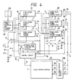
- FIG.4 A still another preferred embodiment of the present invention is illustrated in Fig.4.
- reference numeral 30 denotes a control circuit, i.e. a control circuit 81 having a function to generate characters or figure information to be displayed on the screen
- reference numeral 91 denotes a power supply switch
- 500 denotes an on-screen display circuit
- 3e denotes an on-screen display signal
- 3f denotes control signals of the power supply switches 81 and 91
- Ro, Go and Bo denote a primary color singal including the on-screen information.
- the on-screen display circuit 500 may display the information such as a mode of the playing-back signal 1a during a playing-back operation, for example, in response to the on-screen display signal 3e.
- the control circuit 30 may change over the power supply switches 81 and 91 with the control signal 3f so as to prohibit the power supply from being applied to all the video signal circuits and the croma-video signal circuits 50, 51 and 52 of the NTSC mode, PAL mode and SECAM mode.
- the control circuit 30 may output the on-screen displaying signal 3e to the on-screen displaying circuit 500.
- the on-screen displaying circuit 500 may cause the liquid crystal display device 7 to display in response to the content of the applied on-screen display signal 3e.
- An arrangement position of the on-screen display circuit 500 is not limited to the location shown in Fig. 4, but it may be arranged before or at the middle of or after the NTSC, PAL, SECAM mode video signal circuits 10, 11 and 12 and further it may be arranged at the middle of or after the output of the switch or NTSC, PAL, SECAM croma-video signal circuits 50, 51 and 52, respectively.
- One of the preferred embodiments will be illustrated in Fig. 10 and described later.
- Fig.5 is illustrated one example of a configuration of an active matrix mode displaying device of the liquid crystal displaying device 7.
- Reference numeral 71 denotes a displaying control circuit, 71a a horizontal driving control circuit, 71ba vertical scanning control signal, 72 a polarity alternating circuit, 72a a polarity alternating singal, 73 a horizontal driving circuit, 730 a horizontal driving electrode, 74 a vertical scanning circuit, 740 a vertical scanning electrode, 75 a displaying part, 76 a MOS transistor, 77 a liquid crystal element, 78 a common electrode for applying the same electrical potential to all the liquid crystal elements 77.
- the primary color signals Ro, Go, Bo applied the polarity alternating circuit 72 are reversed at their polarities, and the polarity alternating signals 72a of a positive polarity and a negative polarity are applied to the horizontal driving circuit 73.
- the displaying control circuit 71 may form the horizontal driving signal 71a and the vertical scanning signal 71b in response to the applied displaying control signal, apply them to the horizontal driving circuit 73 and the vertical scanning circuit 74 as as to control their operations.
- the horizontal driving circuit 73 may sample the polarity alternating signal 72a applied in response to the horizontal driving signal 71a and output the sampled voltage to each of the horizontal driving electrodes 730.
- a voltage is applied in sequence to each of the vertical scanning electrodes 740 by the vertical scanning circuit 74 in response to applied vertical scanning signal 71b so as to perform a vertical scanning operation.
- the MOS transistor 76 becomes ON state when a voltage is applied to the gate through the vertical scanning electrodes 740, thereby the display having the applied signal voltage of the horizontal driving electrode 730 written into the liquid crystal 77 is carried out.
- a specified voltage for use in carrying out a display to the primary color signal Bo of the inputs of the polarity alternating circuit 72, and at the same time a specified voltage for preventing the display may be applied to Ro and Go.
- the input primary color singals Ro, Go and Bo of the liquid crystal displaying device 7 may not necessarily be a video signal including the horizontal synchronous signal shown in Fig. 6.
- any of the croma-video signal circuits 50, 51 and 52 of NTSC, PAL and SECAM modes are not necessarily be operated, but a specified voltage may be supplied as the primary color signals Ro, Go and Bo only for a predetermined period of time required for the display from the on-screen display circuit 500 (In case of the aforesaid blue-back display, the specified voltage may always be applied as the primary color signals Ro, Go and Bo.)
- Fig.7 is a configuration figure for showing a still further preferred embodiment of the present invention.
- a different feature of the preferred embodiment shown in Fig.7 from that of the preferred embodiment shown in Fig.4 consists in the fact that a timing signal 71C is supplied from the displaying control circuit 71 to the control circuit 30.
- the displaying control signal outputted from the control circuit 30 for example, there is a method for using the horizontal and vertical synchronous signals.
- an intensity of a tuner (not shown) input electric field is quite weak, it is not possible to get a positive aforesaid horizontal vertical synchronous signal.
- the timing signal 71c is outputted from the displaying control circuit 71 and this is applied to the control circuit 30, thereby the timing of the on-screen displaying information 3e is coincided with the horizontal driving signal 71a and the vertical scanning signal 71b so as to prevent the displayed content from being disturbed.
- 710 denotes a phase comparator
- 711 denotes an LPF
- 712 denotes a VCO
- Vout denotes an output of VCO
- 713 denotes a frequency divider
- Nout denotes an output of the frequency divider
- 714 denotes a timing signal forming circuit.
- phase comparator signal 3CH a horizontal synchronous signal is applied.
- any signal of the NTSC mode, PAL mode and SECAM mode can be displayed as disclosed in the preferred embodiment shown in Fig. 7, it is preferable to set a free run frequency of VCO 712 by coinciding it with any one of the NTSC mode or PAL mode and SECAM mode due to the fact that NTSC mode shows 15.734 kHz, PAL mode and SECAM mode show 15.625 kHz for the different frequencies of the horizontal synchronous signal 3c.
- Fig. 9 there is a method in which two types of VCO 712 and VCO 715 are provided and the aforesaid two types of VCC 712 and 715 are changed over in response to a signal 3cc showing a system of the playing-back signal 1a. In this case, it may be fixed to any one of them (it may be fixed to any VCO).
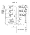
- FIG. 10 A still further preferred embodiment of the present invention is illustrated in Fig. 10.
- a different feature of the preferred embodiment shown in Fig.10 is different from that of Fig.7 consists in the fact that the on-screen information information 3e is not the primary color signals of R, G, B, but is mixed with the complex video signal V. Even in case of the preferred embodiment shown in Fig. 10, the timing signal 71c is outputted to the on-screen display circuit 500, thereby the screen may not be disturbed in case of weak electric field and in case of no signal and then the on-screen display can be performed.
- Fig. 1 the signal distinction corresponding to the signal mode and the recording and playing-back mode is automatically realized by the signal mode distinction circuit 2.
- the aforesaid mode is mechanically specified through a selection of a button or the like.
- the preferred embodiment in this case is shown in Fig. 11.
- reference numeral 20 denotes a signal mode selection switch circuit
- reference numeral 20a denotes a mode distinction signal corresponding to 2a in Fig. 1
- reference numeral 20N denotes a selection switch of NTSC mode signal
- reference numeral 20P denotes a selection switch of PAL mode signal
- reference numeral 20S denotes a selection switch of SECAM mode signal.
- the preferred embodiment is constructed such that the distinction of the signal mode is manually selected by using the signal mode selection switch circuit 20. Even in case of using the configuration shown in Fig. 11, it is possible to perform a changing-over operation between the video signal selection switch 4 and the displaying selection switch 6 in the same manner as that of the preferred embodiments shown in Figs.1 to 10.
- Fig. 11 As regards the mode changing-over operation for SP, LP and EP or the like, the preferred embodiment shown in Fig. 11 can be applied.
- Fig. 12 is a block diagram for showing a still another preferred embodiment of the present invention.
- each of the complex video signals VN, Vp and Vs is directly applied to the NTSC mode, PAL mode and SECAM mode croma-video signal circuits, respectively.
- Applying the circuit shown in Fig. 12 enables the configuration to be simplified more as compared with the case shown in Figs.1 to 11 and at the same time the displaying selection switch 6 is changed over to select the proper signal and to display it.
- Fig.13 is a block diagram for showing a still further preferred embodiment of the present invention and illustrates also the example of the practical configuration of the control circuit 3 shown in Fig. 1.
- reference numeral 31 denotes a controlling part
- 32 denotes a synchronous separating circuit or a synchronous signal forming circuit
- 3d denotes a horizontal synchronous signal
- Vsync denotes a vertical synchronous signal.
- a horizontal synchronous signal is utilized at AGC part or a clamp part, for example, a horizontal synchronous signal is utilized at the clamp part or a burst gate part in case of the croma-video signal circuits 50, 51 and 52, for example, and a horizontal synchronous signal is utilized in the liquid crystal displaying device 7 for use in performing the synchronous scanning operation. Due to this fact, in Fig.
- the aforesaid horizontal synchronous signal is commonly supplied to each of the aforesaid video signal circuits 10, 11, 12 and each of the aforesaid croma-video signal circuits 50, 51, 52 as well as with the aforesaid liquid crystal displaying device 7, thereby each of the aforesaid circuits can be controlled in a substantial same timing and an application of the common circuit enables the configuration to be simplified.
- Fig. 14 is a block diagram for showing a still further preferred embodiment of the present invention and illustrates a practical example of configuration of the control circuit 30 in Fig. 4.
- reference numeral 33 denotes a character and figure information generating circuit.
- the horizontal synchronous signal 3d and the vertical synchronous signal Vsync for use in performing a synchronous scanning are supplied to the liquid crystal displaying device 7 and at the same time applied to the character and figure information generating circuit for use in displaying the on-screen display.
- the liquid crystal displaying device 7 and the character and figure information generating circuit 33 can be operated in a substantial same timing, resulting in that no disturbance in on-screen is found.
- Figs.1 to 14 The preferred embodiments of the present invention have been illustrated in Figs.1 to 14.
- each of the signals 3a, 3b, 3c and 3d has been separately illustrated, and the aforesaid signals 3a, 3b, 3c and 3d may also be combined into one control signal in view of the practical configuration.
- the displaying selection switch 6 has been described as one for changing-over the primary color signals.
- the example of playing-back the video tape of VHS standard has been described and a similar effect can be attained for the case in which signals recorded in the video tape of B standard or 8-mm video standard or other recording media are to be played back.
- the liquid crystal displaying device has been described, and a similar effect can be expected in case that other display devices such as CRT (a cathode ray tube) or a plasma display and the like are used.
- control circuit for controlling an operation of multi-mode video singal recording and playing-back circuit and its output changing-over operation and a control signal can be made in common with the control circuit for controlling a changing-over output of the multi-mode displaying device and the control signal, a size of the circuit can be reduced and at the same time a circuit configuration can be simplified.
- the present invention Since the operation of the circuit not related to the displaying operation can be controlled or stopped by using the common control circuit and the control signal, the present invention has such effects in which the non-required interference can be prevented and the consumption power can be reduced.
Landscapes
- Engineering & Computer Science (AREA)
- Multimedia (AREA)
- Signal Processing (AREA)
- Television Signal Processing For Recording (AREA)
Applications Claiming Priority (2)
| Application Number | Priority Date | Filing Date | Title |
|---|---|---|---|
| JP1194084A JP2771266B2 (ja) | 1989-07-28 | 1989-07-28 | 多方式の映像信号の再生表示装置 |
| JP194084/89 | 1989-07-28 |
Publications (2)
| Publication Number | Publication Date |
|---|---|
| EP0410489A2 true EP0410489A2 (de) | 1991-01-30 |
| EP0410489A3 EP0410489A3 (en) | 1992-09-02 |
Family
ID=16318691
Family Applications (1)
| Application Number | Title | Priority Date | Filing Date |
|---|---|---|---|
| EP19900114508 Withdrawn EP0410489A3 (en) | 1989-07-28 | 1990-07-27 | Multi-mode video signal playback and display device |
Country Status (3)
| Country | Link |
|---|---|
| US (1) | US5432612A (de) |
| EP (1) | EP0410489A3 (de) |
| JP (1) | JP2771266B2 (de) |
Cited By (4)
| Publication number | Priority date | Publication date | Assignee | Title |
|---|---|---|---|---|
| EP0488337A3 (en) * | 1990-11-30 | 1993-05-19 | Hitachi, Ltd. | Magnetic recording apparatus |
| EP0533092A3 (en) * | 1991-09-18 | 1993-08-25 | Hitachi, Ltd. | Video cameras capable of switching an aspect ratio and view finders for use in the same |
| EP0687107A3 (de) * | 1994-06-07 | 1996-07-31 | Matsushita Electric Industrial Co Ltd | Fernsehempfänger, der eine Videoaufnahme-/Wiedergabe-Einrichtung enthält |
| US6463210B1 (en) | 1992-09-11 | 2002-10-08 | Pioneer Corporation | Video disc having an aspect ratio information and video disc player having an aspect ratio converting function |
Families Citing this family (2)
| Publication number | Priority date | Publication date | Assignee | Title |
|---|---|---|---|---|
| JP2003009160A (ja) * | 2001-06-27 | 2003-01-10 | Pioneer Electronic Corp | カラー方式判別装置およびカラー方式判別方法 |
| KR20040067579A (ko) * | 2003-01-24 | 2004-07-30 | 삼성전자주식회사 | 액정 표시 장치의 백라이트 구동 장치 |
Family Cites Families (15)
| Publication number | Priority date | Publication date | Assignee | Title |
|---|---|---|---|---|
| GB1412091A (en) * | 1973-01-17 | 1975-10-29 | Sony Corp | Systems for recording and reproducing colour television signals |
| DE3137447C2 (de) * | 1980-11-19 | 1987-02-19 | Philips Patentverwaltung Gmbh, 2000 Hamburg | Farbfernsehempfänger-Schaltungsanordnung zur Identifikation der Norm |
| BE889952A (fr) * | 1981-08-12 | 1981-12-01 | Erumba Gotha H | Systeme de mise en commun de circuits pour televiseur et videocassette ou videobande dans un meme boitier |
| JPS58139587A (ja) * | 1982-02-13 | 1983-08-18 | Mitsubishi Electric Corp | 映像再生装置 |
| JPS58186279A (ja) * | 1982-04-23 | 1983-10-31 | Sony Corp | デジタルvtr |
| JPS59176985A (ja) * | 1983-03-26 | 1984-10-06 | Citizen Watch Co Ltd | 液晶テレビ受信装置 |
| US4694348A (en) * | 1985-06-14 | 1987-09-15 | Citizen Watch Co., Ltd. | Method of driving liquid crystal display panel of TV receiver |
| JPH0824363B2 (ja) * | 1985-06-18 | 1996-03-06 | カシオ計算機株式会社 | 磁気記録再生装置 |
| JPH0719330B2 (ja) * | 1985-12-18 | 1995-03-06 | 松下電器産業株式会社 | 映像信号記録再生装置 |
| DE3720353A1 (de) * | 1987-06-19 | 1989-01-05 | Online Tech Datenuebertragungs | Verfahren und schaltungsanordnung zur ansteuerung einer bildwiedergabeeinrichtung |
| JPS643391A (en) * | 1987-06-26 | 1989-01-09 | Nippon Kokan Kk | Pipe unit for penetrating to wall |
| JP2638815B2 (ja) * | 1987-07-28 | 1997-08-06 | ソニー株式会社 | ディスク再生装置 |
| JPH0195692A (ja) * | 1987-10-08 | 1989-04-13 | Victor Co Of Japan Ltd | 磁気記録再生装置 |
| JP2644797B2 (ja) * | 1988-01-25 | 1997-08-25 | 松下電器産業株式会社 | ビデオテープレコーダ |
| DE68915228T2 (de) * | 1988-09-02 | 1994-12-15 | Sanyo Electric Co | Phasensynchronisierschaltung in einem Videosignalempfänger und Verfahren zur Herstellung der Phasensynchronisation. |
-
1989
- 1989-07-28 JP JP1194084A patent/JP2771266B2/ja not_active Expired - Fee Related
-
1990
- 1990-07-27 US US07/558,521 patent/US5432612A/en not_active Expired - Fee Related
- 1990-07-27 EP EP19900114508 patent/EP0410489A3/en not_active Withdrawn
Cited By (8)
| Publication number | Priority date | Publication date | Assignee | Title |
|---|---|---|---|---|
| EP0488337A3 (en) * | 1990-11-30 | 1993-05-19 | Hitachi, Ltd. | Magnetic recording apparatus |
| US5499145A (en) * | 1990-11-30 | 1996-03-12 | Hitachi, Ltd. | Magnetic recording apparatus with capability of recording signals of a plurality of different television systems |
| EP0533092A3 (en) * | 1991-09-18 | 1993-08-25 | Hitachi, Ltd. | Video cameras capable of switching an aspect ratio and view finders for use in the same |
| US5414463A (en) * | 1991-09-18 | 1995-05-09 | Hitachi, Ltd. | Video cameras capable of switching an aspect ratio and view finders for use in the same |
| US6463210B1 (en) | 1992-09-11 | 2002-10-08 | Pioneer Corporation | Video disc having an aspect ratio information and video disc player having an aspect ratio converting function |
| US6968121B2 (en) | 1992-09-11 | 2005-11-22 | Pioneer Electronic Corporation | Video disc having an aspect ratio information and video disc player having an aspect ratio converting function |
| EP0687107A3 (de) * | 1994-06-07 | 1996-07-31 | Matsushita Electric Industrial Co Ltd | Fernsehempfänger, der eine Videoaufnahme-/Wiedergabe-Einrichtung enthält |
| CN1086092C (zh) * | 1994-06-07 | 2002-06-05 | 松下电器产业株式会社 | 自带录放像装置的电视机 |
Also Published As
| Publication number | Publication date |
|---|---|
| EP0410489A3 (en) | 1992-09-02 |
| US5432612A (en) | 1995-07-11 |
| JPH0360288A (ja) | 1991-03-15 |
| JP2771266B2 (ja) | 1998-07-02 |
Similar Documents
| Publication | Publication Date | Title |
|---|---|---|
| EP0096628B1 (de) | Einrichtung zum Kombinieren von Bildsignalen mit grafischen und alphanumerischen Zeichen eines Computers | |
| EP0096627B1 (de) | Interaktives Informationsanzeigesystem mit einem Rechner | |
| US5638485A (en) | Video signal processing apparatus for processing video signals with different aspect ratios | |
| EP0488337B1 (de) | Magnetisches Aufzeichnungsgerät | |
| US5432612A (en) | Multi-mode video signal playback and display device | |
| US5502487A (en) | Character signal display for a camcorder using existent synchronization signals for character display | |
| JP3141404B2 (ja) | マルチスキャンモニタの入力映像信号のシステム判別方法及びマルチスキャンモニタ | |
| JPH03263984A (ja) | 映像処理装置 | |
| JP2508610B2 (ja) | 自動ホワイトバランス調整回路 | |
| JP2868366B2 (ja) | オンスクリーン信号を利用したバックスクリーン表示方法及び装置 | |
| JPH05199462A (ja) | 映像信号処理回路 | |
| JPH0695766B2 (ja) | 自動ホワイトバランス調整回路 | |
| KR960042655A (ko) | 멀티형 비디오 카세트 레코더의 기준주파수 스위칭회로 | |
| KR920001160B1 (ko) | 비데오 테이프 레코오더 녹화시 온스크린문자 녹화회로 | |
| JP3157785B2 (ja) | 映像信号処理回路及び同期分離システム | |
| JP3235423B2 (ja) | 磁気録画再生装置の目詰まり検知装置 | |
| JPS63142780A (ja) | 文字信号発生装置 | |
| KR19980034756A (ko) | Osd(on-screen display) 문자에 대한 색상조정기능을 갖춘 영상재생장치 | |
| KR200162300Y1 (ko) | 표시 장치의 동기 신호 발생 장치 | |
| JPH06233235A (ja) | 不要信号記録阻止装置 | |
| JPH09139896A (ja) | 自動画面設定回路 | |
| JPH05268569A (ja) | 映像信号切換装置 | |
| JPH07231406A (ja) | 字幕移動機能付き子画面表示回路 | |
| JPH11113017A (ja) | 信号切換回路 | |
| JPH066714A (ja) | モニタ装置 |
Legal Events
| Date | Code | Title | Description |
|---|---|---|---|
| PUAI | Public reference made under article 153(3) epc to a published international application that has entered the european phase |
Free format text: ORIGINAL CODE: 0009012 |
|
| 17P | Request for examination filed |
Effective date: 19900809 |
|
| AK | Designated contracting states |
Kind code of ref document: A2 Designated state(s): DE FR GB IT |
|
| PUAL | Search report despatched |
Free format text: ORIGINAL CODE: 0009013 |
|
| AK | Designated contracting states |
Kind code of ref document: A3 Designated state(s): DE FR GB IT |
|
| 17Q | First examination report despatched |
Effective date: 19950131 |
|
| GRAG | Despatch of communication of intention to grant |
Free format text: ORIGINAL CODE: EPIDOS AGRA |
|
| STAA | Information on the status of an ep patent application or granted ep patent |
Free format text: STATUS: THE APPLICATION HAS BEEN WITHDRAWN |
|
| 18W | Application withdrawn |
Withdrawal date: 19960514 |