EP0410732A2 - Système d'emmagasinage de plaques lithographiques - Google Patents
Système d'emmagasinage de plaques lithographiques Download PDFInfo
- Publication number
- EP0410732A2 EP0410732A2 EP90308169A EP90308169A EP0410732A2 EP 0410732 A2 EP0410732 A2 EP 0410732A2 EP 90308169 A EP90308169 A EP 90308169A EP 90308169 A EP90308169 A EP 90308169A EP 0410732 A2 EP0410732 A2 EP 0410732A2
- Authority
- EP
- European Patent Office
- Prior art keywords
- lithographic plate
- lithographic
- plate
- hook
- carriage means
- Prior art date
- Legal status (The legal status is an assumption and is not a legal conclusion. Google has not performed a legal analysis and makes no representation as to the accuracy of the status listed.)
- Granted
Links
- 238000005192 partition Methods 0.000 claims abstract description 14
- 239000000725 suspension Substances 0.000 description 8
- 230000001174 ascending effect Effects 0.000 description 3
- 230000002452 interceptive effect Effects 0.000 description 3
- 239000000543 intermediate Substances 0.000 description 2
- 238000000034 method Methods 0.000 description 2
- 230000002411 adverse Effects 0.000 description 1
- 238000013459 approach Methods 0.000 description 1
- 239000003638 chemical reducing agent Substances 0.000 description 1
- 230000009850 completed effect Effects 0.000 description 1
- 230000008878 coupling Effects 0.000 description 1
- 238000010168 coupling process Methods 0.000 description 1
- 238000005859 coupling reaction Methods 0.000 description 1
- 238000003780 insertion Methods 0.000 description 1
- 230000037431 insertion Effects 0.000 description 1
- 239000000463 material Substances 0.000 description 1
- 230000003405 preventing effect Effects 0.000 description 1
- 230000002265 prevention Effects 0.000 description 1
Images





Classifications
-
- B—PERFORMING OPERATIONS; TRANSPORTING
- B41—PRINTING; LINING MACHINES; TYPEWRITERS; STAMPS
- B41F—PRINTING MACHINES OR PRESSES
- B41F27/00—Devices for attaching printing elements or formes to supports
- B41F27/12—Devices for attaching printing elements or formes to supports for attaching flexible printing formes
- B41F27/1206—Feeding to or removing from the forme cylinder
Definitions
- the present invention relates to a storing system of lithographic plates which are used for printing newspapers and the like so that they may be taken out so as to be mounted to a rotary press.
- Lithographic plates are usually conveyed by means of a hanger conveyor in a suspended manner. Before they are mounted to a rotary press, they are temporarily stored in a shelf. The stored lithographic plates are required to be selectively taken out from the storage shelf so that they may be mounted to a designated rotary press.
- a storage shelf is disclosed in, for example, in United States Patent No. 4,903,817 according to which the lithographic plates must be taken out on the basis of "first-in, first-out". In other words, lithographic plates cannot be taken out from the storage shelf at random or selectively.
- a lithographic plate P which has been transported by a hanger conveyor H is first disengaged from the conveyor H and slides along a guiding chute G so as to be received by a pair of supporting sections.
- the lithographic plate P is then dropped to a lateral feed conveyor C which in turn feeds the lithographic plate Pinto a shelf comprising a plurality of endlessly revolving trays T.
- the shelf S is so constructed that each time a lithographic plate P is received by a tray T from the lateral feed conveyor C, the tray T descends by the mounting pitch of the trays; and the next empty tray T is adapted to receive the next lithographic plate P.
- a number of lithographic plates may be stored on the trays in the descending path.
- the lithographic plate P may be taken out from an exit D.
- the emptied trays are then sent upward in the ascending path.
- the lithographic plates P may be stored in the descending path of the trays between the feeding end of the lateral feed conveyor C and the exit.
- a lithographic plate storing system comprising a lifting member for engaging with a hook of a lithographic plate, a carriage means including a lithographic plate engagement member which is adapted to be located in an advanced position while said lifting member is lowered so as to receive said lithographic plate and in a retreated position while said lifiting member is raised so as not to interfere therewith and a pusher for sidewardly pushing said lithographic plate while said lithographic plate is supported by said engagement member, and a fixed storage shelf comprising a plurality of perpendicularly spaced-apart partitions.
- the lifting member engages with the hook of a lithographic plate which lies on a lateral feed conveyor horizontally; and raises the lithographic plate into a suspended form.
- the lithographic plate is then received by an engagement member carried by a carriage means which is adapted to run along the opening side of the fixed storage shelf.
- the pusher provided to the carriage means pushes the lithographic plate suspended by said engagement member sidewardly so as to insert the lithographic plate into a space defined by adjacent partitions of said fixed storage shelf.
- the lithographic plates held between the adjacent partitions may be taken out at random and selectively without regard to the order of their storage into the shelf.
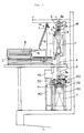
- a lithographic plate 1 which has been conveyed by a conveyor H in a suspended manner slides down along a chute G so as to be received in a horizontal form by the uppermost shelf of a support means E.
- the support means E comprises a plurality of shelves each comprising a pair of opposing support members.
- the support means E is arranged in multiple stages of like structures.
- the lithographic plate 1 received by the uppermost shelf is dropped to the next stage shelf as the uppermost opposing support members open.
- the lithographic plate 1 is finally received by an intermittently driven conveyor C so as to be fed forward with a downwardly facing hook 1′ placed at the frontmost position.
- an upright shaft 2 is erected.
- a driving sprocket 3a and driven sprocket 3b are provided at the upper and lower ends of the shaft 2, respectively with a driving chain spanning therebetween.
- a lithographic plate lifting member 5 is connected to the driving chain 4 having a support member 6 which is pivotably connected to the lithographic plate lifting member 5.
- a lithographic plate engagement member 7 is secured so as to engage with the hook 1′ of the lithographic plate 1.
- a lithographic plate holding lever 8 is pivotably supported to the support member 6 so that the top of the hook 1′ engaging with the engagement member 7 may be securely held.
- the lever 8 is adapted to be operated to take two positions, open and closed, by a pneumatic cylinder 9 mounted to the support member 6.
- the lifting member 5 includes a guiding member 10 slidably engageable with a guide rail 2′ formed in the upright shaft 2 and further includes a motor M for driving the shaft 6′ of the support member 6, a speed reducer V and a coupling, etc.
- the engaging section 7′ of the engagement member 7 picks up the hook 1′ and thus lifts the lithographic plate 1 upward.
- the lithographic plate 1 may be suspended as shown by solid line in Fig. 1.
- the thus suspended lithographic plate 1 may be turned by 90 degrees about the shaft 6′ to the position as shown in two-dot-dash line in Fig. 1. Then, the suspended lithographic plate 1 may descend without interfering with the take-out end of the conveyor C.
- the lifting member 5 engaging with the lithographic plate 1 is then caused to descend by the chain 4 to the lowermost position as shown in Fig. 2.
- reference numeral 20 denotes a frame supporting a carriage means 30 (described later) for storing lithographic plate(s) 1 into a storage shelf 40 in a suspended manner.
- said swivelable engagement members 21, 21 are supported by the respective shafts 24, 24 mounted to a pair of plates 23, 23 which are respectively secured to beams 22, 22 supported by the frame 20. And, the respective shafts 24, 24 are adapted to be turned 90 degrees so as to face with each other.
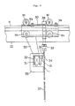
- the swivelable engaging members 21, 21 may take the two selective positions, namely, the one which is horizontal as shown by solid line in Fig. 4 for engaging with the hook 1′ of a lithographic plate 1 and the other position which is vertical as shown by two-dot-dash line in Fig. 4 to allow the lithographic plate 1 to drop therefrom.
- the swivelable engaging members 21, 21 are adapted to advance and retreat as shown by solid line and two-dot-dash line respectively in Fig. 2 by means of a motor 26.
- the engaging section 7′ of the engagement member 7 is adapted to engage with the intermediate portion of the hook 1′ while the swivelable engaging members 21, 21 are adapted to engage with the two end portions of the hook 1′.
- the advanced, horizontally held swivelable engaging members 21, 21 may engage with the two end portions of the hook 1′ without interfering with the engaging section 7′ of another engagement member 7.
- the engaging section 7′ of the engagement member 7 disengages from the hook 1′; and then, the hook 1 ′ are suspended by means, only, of the swivelable engaging members 21, 21.
- the swivelable engaging members 21, 21 are caused to retreat by means of the motor 26 to the position as shown by two-dot-dash line in Fig. 2 so as to be outside the moving path of the engaging section 7′; then, the lifting member 5 is capable of ascending without interfering with the swivelable engaging members 21, 21, so that the lifting member 5 may be again raised in order to receive the next lithographic plate, and turned 90 degrees, and then await the next lithographic plate at the take-out end of the conveyor C.
- a pair of rails R, R are disposed so as to guide the carriage means 30.
- the carriage means 30 comprises a pair of running wheels W1 ,W1, a pair of guide rollers W2 , W2 ,and a pair of floating prevention rollers w3, W3 .
- a driving sprocket 27 and a driven sprocket 28 are respectively disposed; and a belt 29 spans therebetween so as to drive the carriage means 30 attached thereto.
- a fixture 32 including a rod-less cylinder 31 is secured via a york 33.
- the stroke of the piston (not shown) of the rod-less cylinder 31 is substantially equal to the full length thereof and is adapted to actuate to and fro a pusher 34 along a guide (not shown) provided to the fixture 32.
- the pusher 34 is further adapted to be reversely actuated as it reaches the stroke end limit switch LS1 ; and stops as it reaches the retreat end limit switch LS2.
- a pair of space-apart, inversely C-shaped fixtures 35, 35 are secured to the fixing beam 32.
- a lithographic plate supension plate 36 is fixed, so as to suspend a lithographic plate 1 with the upper edge 36′ thereof at the level slightly lower than the level of the hook 1′ when the lithographic plate 1 is suspended by the pair of swivelable engaging members 21, 21.
- a plate 37 for preventing vibration of the lithographic plate 1 is provided at the lower free end thereof.
- a plate 39 is attached to the carriage means 30 so as to urge the hook portion 1′ of the lithographic plate 1 toward the upper edge 36′ of the suspension plate 36 by means of a cylinder 38.
- the pair of swivelable engaging members 21, 21 are turned to the position shown by two-dot-dash line in Fig. 4, the lithographic plate 1 drops therefrom; and the hook 1′ thereof is received by the upper edge 36′ of the suspension plate 36; and then, the plate 39 is lowered to the position as shown by two-dot-dash line in Fig. 4 so as to positively hold the hook 1′ against the upper edge 36′ of the suspension plate 36.
- a llthographic plate storage shelf 40 is provided at one of the lower sides of the carriage means 30.
- the shelf 40 comprises a number of perpendicularly spaced-apart partitions 41, 41...; and a pair of photosensors 42 are provided to each of the opposing surfaces of the partitions 41 at the different levels.
- the opening of the shelf 40 faces toward the running path of the carriage means 30.
- a photo sensor 42 is operated so that a lamp is lit on the panel 43 for indicating the given number of the particular space defined by said pair of partitions; and at the same time, the type of said lithographic plate as registered when the plate 1 was put to the hanger conveyor H is also indicated.
- the carriage means 30 first approaches (from left to right in Fig. 6) the pair of the swivelable engaging members 21, 21 which are holding a lithographic plate 1 as mentioned before; and receives the lithographic plate therefrom as explained hereinabove with reference to Fig. 4 by means of the suspension plate 36. Thereafter, the carriage means 30 runs along the front opening of the shelf 40 and stops in front of an empty space between a pair of partitions 41, 41. Then, the rod-less cylinder 31 is operated so as to actuate the pusher 34 in the leftward direction in Fig. 4. The righthand edge of the lithographic plate 1 is thus pushed such that the lithographic plate 1 is inserted into the space as the desired location.
- Each partition 41 includes a suspension fitting 41′ which is at substantially the same level with the edge 36′ of the suspension plate 36, so that a lithographic plate 1 inserted into a space between adjacent partitions 41, 41 may be suspended vertically by means of said suspension fitting 41′.
- a free end of a flexible supporting sheath 50 is connected to the carriage means 30 so as to supply power to the carriage means 30.
- horizontally conveyed lithographic plates may be picked up so as to change into a vertically suspended position. And while maintaining the vertically suspended position, they are conveyed by the carriage means and are serially inserted into the spaces defined by adjacent, perpendicularly spaced-apart partitions.
- first-in, first-out is no longer applicable; and any desired lithographic plate may be selectively picked out regardless of the order of storage so as to be sent to the position of a rotary presses.
Landscapes
- Warehouses Or Storage Devices (AREA)
Applications Claiming Priority (2)
| Application Number | Priority Date | Filing Date | Title |
|---|---|---|---|
| JP1989087443U JPH0326541U (fr) | 1989-07-27 | 1989-07-27 | |
| JP87443/89 | 1989-07-27 |
Publications (3)
| Publication Number | Publication Date |
|---|---|
| EP0410732A2 true EP0410732A2 (fr) | 1991-01-30 |
| EP0410732A3 EP0410732A3 (en) | 1991-07-31 |
| EP0410732B1 EP0410732B1 (fr) | 1994-09-07 |
Family
ID=13915005
Family Applications (1)
| Application Number | Title | Priority Date | Filing Date |
|---|---|---|---|
| EP90308169A Expired - Lifetime EP0410732B1 (fr) | 1989-07-27 | 1990-07-25 | Système d'emmagasinage de plaques lithographiques |
Country Status (4)
| Country | Link |
|---|---|
| US (1) | US5118240A (fr) |
| EP (1) | EP0410732B1 (fr) |
| JP (1) | JPH0326541U (fr) |
| DE (1) | DE69012252T2 (fr) |
Families Citing this family (3)
| Publication number | Priority date | Publication date | Assignee | Title |
|---|---|---|---|---|
| JPH0522452U (ja) * | 1991-08-30 | 1993-03-23 | 村田機械株式会社 | パツケージ移載装置 |
| DE19805420C2 (de) * | 1998-02-11 | 2000-02-17 | Heinz Rathmer | Präsentationseinrichtung |
| DE102005055116A1 (de) * | 2005-11-18 | 2007-05-24 | Maschinenfabrik Wifag | Druckformzuordnungseinrichtung in einer Rotationsdruckmaschine |
Family Cites Families (8)
| Publication number | Priority date | Publication date | Assignee | Title |
|---|---|---|---|---|
| US3715040A (en) * | 1970-07-14 | 1973-02-06 | Advanced Digital Syst Inc | Data accessing system |
| JPS57189901A (en) * | 1981-05-20 | 1982-11-22 | Fujitsu General Ltd | Stock control system |
| DE3172116D1 (en) * | 1981-05-20 | 1985-10-10 | Schenck Ag Carl | Press unloading apparatus |
| JPH0624849B2 (ja) * | 1985-09-27 | 1994-04-06 | 株式会社東京機械製作所 | 刷版搬送・着脱システム |
| US4727807A (en) * | 1985-09-30 | 1988-03-01 | Tokyo Kikai Seisakusho | Apparatus for automatically mounting and removing printing plates in rotary printing press |
| US4866661A (en) * | 1986-03-26 | 1989-09-12 | Prins Maurits L De | Computer controlled rental and sale system and method for a supermarket and the like |
| JPH051395Y2 (fr) * | 1987-07-30 | 1993-01-14 | ||
| DE3738973C1 (de) * | 1987-11-17 | 1989-05-18 | Kleinewefers Gmbh | Vorrichtung zum Auswechseln elastischer Superkalander-Walzen |
-
1989
- 1989-07-27 JP JP1989087443U patent/JPH0326541U/ja active Pending
-
1990
- 1990-07-19 US US07/555,265 patent/US5118240A/en not_active Expired - Fee Related
- 1990-07-25 DE DE69012252T patent/DE69012252T2/de not_active Expired - Fee Related
- 1990-07-25 EP EP90308169A patent/EP0410732B1/fr not_active Expired - Lifetime
Also Published As
| Publication number | Publication date |
|---|---|
| US5118240A (en) | 1992-06-02 |
| JPH0326541U (fr) | 1991-03-18 |
| EP0410732B1 (fr) | 1994-09-07 |
| DE69012252T2 (de) | 1995-02-23 |
| EP0410732A3 (en) | 1991-07-31 |
| DE69012252D1 (de) | 1994-10-13 |
Similar Documents
| Publication | Publication Date | Title |
|---|---|---|
| US5930144A (en) | Parts supply system | |
| US7210889B2 (en) | Circulating storage system | |
| EP0240535B1 (fr) | Installation pour rassembler des caisses a claire-voie et analogues | |
| EP0452159A2 (fr) | Convoyeur de plateaux de pièces | |
| EP0594079B1 (fr) | Procédé et dispositif pour le transport de plateaux | |
| KR19980080629A (ko) | 시트 더미를 언로딩하는 방법 및 장치 | |
| EP0410732B1 (fr) | Système d'emmagasinage de plaques lithographiques | |
| JPH05116877A (ja) | 物品の搬送装置 | |
| JPH0134886B2 (fr) | ||
| JP3946375B2 (ja) | トレー移送機構及び該トレー移送機構を用いた部品供給装置 | |
| JP2771745B2 (ja) | 物品の搬送装置 | |
| CN214398429U (zh) | 一种料盘的搬运供应装置 | |
| EP0681887A2 (fr) | Dispositif et procédé d'alimentation de pièces | |
| JP2792794B2 (ja) | ゴミの分別搬送装置 | |
| JP2816193B2 (ja) | アンプル収納ケース及び該ケースを使用したアンプル補給装置並びに該ケースの搬入装置及び搬出装置 | |
| JP3878354B2 (ja) | トレー移送機構及び該トレー移送機構を用いた部品供給装置 | |
| US5294101A (en) | Automatic film-loading device for sheet film cassettes | |
| JP3447790B2 (ja) | 部品供給装置 | |
| JP2771743B2 (ja) | 物品の搬送装置 | |
| JP2000269684A (ja) | 部品供給装置 | |
| JP3447841B2 (ja) | 収容箱ストックモジュールおよびこれを用いた部品供給装置 | |
| JPH0730234U (ja) | 育苗箱自動供給装置 | |
| JP2793934B2 (ja) | ゴミの分別搬送装置 | |
| JP3344870B2 (ja) | 部品供給装置 | |
| JPH0636026Y2 (ja) | 刷版移送機 |
Legal Events
| Date | Code | Title | Description |
|---|---|---|---|
| PUAI | Public reference made under article 153(3) epc to a published international application that has entered the european phase |
Free format text: ORIGINAL CODE: 0009012 |
|
| AK | Designated contracting states |
Kind code of ref document: A2 Designated state(s): CH DE GB IT LI |
|
| 17P | Request for examination filed |
Effective date: 19901228 |
|
| PUAL | Search report despatched |
Free format text: ORIGINAL CODE: 0009013 |
|
| AK | Designated contracting states |
Kind code of ref document: A3 Designated state(s): CH DE GB IT LI |
|
| 17Q | First examination report despatched |
Effective date: 19930406 |
|
| GRAA | (expected) grant |
Free format text: ORIGINAL CODE: 0009210 |
|
| AK | Designated contracting states |
Kind code of ref document: B1 Designated state(s): CH DE GB IT LI |
|
| PG25 | Lapsed in a contracting state [announced via postgrant information from national office to epo] |
Ref country code: IT Free format text: LAPSE BECAUSE OF FAILURE TO SUBMIT A TRANSLATION OF THE DESCRIPTION OR TO PAY THE FEE WITHIN THE PRESCRIBED TIME-LIMIT;WARNING: LAPSES OF ITALIAN PATENTS WITH EFFECTIVE DATE BEFORE 2007 MAY HAVE OCCURRED AT ANY TIME BEFORE 2007. THE CORRECT EFFECTIVE DATE MAY BE DIFFERENT FROM THE ONE RECORDED. Effective date: 19940907 |
|
| REF | Corresponds to: |
Ref document number: 69012252 Country of ref document: DE Date of ref document: 19941013 |
|
| PLBE | No opposition filed within time limit |
Free format text: ORIGINAL CODE: 0009261 |
|
| STAA | Information on the status of an ep patent application or granted ep patent |
Free format text: STATUS: NO OPPOSITION FILED WITHIN TIME LIMIT |
|
| 26N | No opposition filed | ||
| PGFP | Annual fee paid to national office [announced via postgrant information from national office to epo] |
Ref country code: GB Payment date: 19960716 Year of fee payment: 7 |
|
| PGFP | Annual fee paid to national office [announced via postgrant information from national office to epo] |
Ref country code: DE Payment date: 19960802 Year of fee payment: 7 |
|
| PGFP | Annual fee paid to national office [announced via postgrant information from national office to epo] |
Ref country code: CH Payment date: 19960805 Year of fee payment: 7 |
|
| PG25 | Lapsed in a contracting state [announced via postgrant information from national office to epo] |
Ref country code: GB Free format text: LAPSE BECAUSE OF NON-PAYMENT OF DUE FEES Effective date: 19970725 |
|
| PG25 | Lapsed in a contracting state [announced via postgrant information from national office to epo] |
Ref country code: LI Free format text: LAPSE BECAUSE OF NON-PAYMENT OF DUE FEES Effective date: 19970731 Ref country code: CH Free format text: LAPSE BECAUSE OF NON-PAYMENT OF DUE FEES Effective date: 19970731 |
|
| REG | Reference to a national code |
Ref country code: CH Ref legal event code: PL |
|
| GBPC | Gb: european patent ceased through non-payment of renewal fee |
Effective date: 19970725 |
|
| PG25 | Lapsed in a contracting state [announced via postgrant information from national office to epo] |
Ref country code: DE Free format text: LAPSE BECAUSE OF NON-PAYMENT OF DUE FEES Effective date: 19980401 |