EP0410814A2 - Kraftfahrzeugsitz mit einem Mechanismus zum Erleichtern des Zugangs - Google Patents
Kraftfahrzeugsitz mit einem Mechanismus zum Erleichtern des Zugangs Download PDFInfo
- Publication number
- EP0410814A2 EP0410814A2 EP90308325A EP90308325A EP0410814A2 EP 0410814 A2 EP0410814 A2 EP 0410814A2 EP 90308325 A EP90308325 A EP 90308325A EP 90308325 A EP90308325 A EP 90308325A EP 0410814 A2 EP0410814 A2 EP 0410814A2
- Authority
- EP
- European Patent Office
- Prior art keywords
- arm
- seat
- lever
- lower arm
- locking
- Prior art date
- Legal status (The legal status is an assumption and is not a legal conclusion. Google has not performed a legal analysis and makes no representation as to the accuracy of the status listed.)
- Granted
Links
Images





Classifications
-
- B—PERFORMING OPERATIONS; TRANSPORTING
- B60—VEHICLES IN GENERAL
- B60N—SEATS SPECIALLY ADAPTED FOR VEHICLES; VEHICLE PASSENGER ACCOMMODATION NOT OTHERWISE PROVIDED FOR
- B60N2/00—Seats specially adapted for vehicles; Arrangement or mounting of seats in vehicles
- B60N2/02—Seats specially adapted for vehicles; Arrangement or mounting of seats in vehicles the seat or part thereof being movable, e.g. adjustable
- B60N2/22—Seats specially adapted for vehicles; Arrangement or mounting of seats in vehicles the seat or part thereof being movable, e.g. adjustable the back-rest being adjustable
- B60N2/235—Seats specially adapted for vehicles; Arrangement or mounting of seats in vehicles the seat or part thereof being movable, e.g. adjustable the back-rest being adjustable by gear-pawl type mechanisms
- B60N2/2352—Seats specially adapted for vehicles; Arrangement or mounting of seats in vehicles the seat or part thereof being movable, e.g. adjustable the back-rest being adjustable by gear-pawl type mechanisms with external pawls
-
- B—PERFORMING OPERATIONS; TRANSPORTING
- B60—VEHICLES IN GENERAL
- B60N—SEATS SPECIALLY ADAPTED FOR VEHICLES; VEHICLE PASSENGER ACCOMMODATION NOT OTHERWISE PROVIDED FOR
- B60N2/00—Seats specially adapted for vehicles; Arrangement or mounting of seats in vehicles
- B60N2/02—Seats specially adapted for vehicles; Arrangement or mounting of seats in vehicles the seat or part thereof being movable, e.g. adjustable
- B60N2/04—Seats specially adapted for vehicles; Arrangement or mounting of seats in vehicles the seat or part thereof being movable, e.g. adjustable the whole seat being movable
- B60N2/12—Seats specially adapted for vehicles; Arrangement or mounting of seats in vehicles the seat or part thereof being movable, e.g. adjustable the whole seat being movable slidable and tiltable
- B60N2/123—Seats specially adapted for vehicles; Arrangement or mounting of seats in vehicles the seat or part thereof being movable, e.g. adjustable the whole seat being movable slidable and tiltable and provided with memory locks
-
- B—PERFORMING OPERATIONS; TRANSPORTING
- B60—VEHICLES IN GENERAL
- B60N—SEATS SPECIALLY ADAPTED FOR VEHICLES; VEHICLE PASSENGER ACCOMMODATION NOT OTHERWISE PROVIDED FOR
- B60N2/00—Seats specially adapted for vehicles; Arrangement or mounting of seats in vehicles
- B60N2/02—Seats specially adapted for vehicles; Arrangement or mounting of seats in vehicles the seat or part thereof being movable, e.g. adjustable
- B60N2/20—Seats specially adapted for vehicles; Arrangement or mounting of seats in vehicles the seat or part thereof being movable, e.g. adjustable the back-rest being tiltable, e.g. to permit easy access
- B60N2/206—Seats specially adapted for vehicles; Arrangement or mounting of seats in vehicles the seat or part thereof being movable, e.g. adjustable the back-rest being tiltable, e.g. to permit easy access to a position in which it can be used as a support for objects, e.g. as a tray
Definitions
- the present invention relates generally to a seat structure for an automotive vehicle. More specifically, the invention relates to an automotive seat structure with a walk-in mechanism for frontwardly inclining a seat back and, simultaneously, shifting the seat frontwardly for providing a clearance for passing into a rear seat. Further particularly, the invention relates to an automotive seat structure which can fold the seat back beyond the frontwardly inclined position for orienting the back side of the seat back substantially in horizontal so that the back side of the seat back can be used as a table. Additionally, the invention relates to a seat structure which is particularly adapted for a cab-over type wagon, or mini-bus having front, center and rear seats.
- Japanese Patent First (unexamined) Publication (Tokkai) Showa 62-29440 disclose an automotive seat, particularly adapted for cab-over type wagon.
- the disclosed seat is particularly designed as center or intermediate seat in particular type of wagon having front, center or intermediate and rear seats.
- the seat has a seat back to be inclined frontwardly.
- the seat is slidable frontwardly when the seat back is inclined so as to provide a passage for rear seat passengers to pass therethrough.
- Such mechanism is per se known as walk-in mechanism.
- the above-identified prior proposed invention further proposes the seat which has a seat back being capable of further inclined so that the back side of the seat back can be oriented substantially in horizontal.
- Such seat back position may be hereafter referred to as "folded position".
- the back side oriented substantially in horizontal may serve for placing luggage, or, in the alternative, for using as table.
- an object of the present invention to provide an automotive seat structure with a compact walk-in mechanism and mechanism for folding seat into the folded position.
- an automotive seat structure including a seat cushion and a seat back which is operable for selecting a seat back reclining position at first position, for frontwardly inclined position for providing space for a passenger to pass therethrough at a second position and for orienting the seat back at substantially horizontal position, comprises: a base plate fixed to the seat cushion; a first arm pivotably mounted on the base plate; a second arm fixed to the seat back of the seat, the second arm belong pivotally connected to the first arm at one end; a first locking means for locking the first and second arms in substantially alignment with each other; a second locking means for locking the first and second arms locked in alignment by the first means at a selected angular position relative to the seat cushion at the first position of the seat back; a third locking means for locking the second arm while the seat back is placed at the third position; and a manually operable member associated with the first arm for pivotal movement therewith, the manually operable member having first component extending frontwardly and a second component extending rearwardly, the first and second components
- the automotive seat structure further comprises an elastic member associated with the second arm for elastically biasing the second arm for eliminating free movement of the second arm due to play.
- the automotive seat structure may further comprise a seat slide mechanism cooperated with the second locking means for preventing longitudinal displacement of seat while the second locking means is in locking state and responsive to releasing of locking of the second means for releasing locking for permitting frontward movement of the seat.
- the automotive seat structure may further comprise a seat back hinge assembly including a first arm pivotally mounted on a base plate and a second arm pivotally connected to the first arm, the first arm being associated with a first latch and second second arm being associated with a second latch, which first and second latches are cooperated via a link disposed therebetween for permitting the seat back to be operated into the first, second and third positions.
- a seat back hinge assembly including a first arm pivotally mounted on a base plate and a second arm pivotally connected to the first arm, the first arm being associated with a first latch and second second arm being associated with a second latch, which first and second latches are cooperated via a link disposed therebetween for permitting the seat back to be operated into the first, second and third positions.
- an automotive seat structure comprises: a base plate fixed to a seat cushion; a lower arm pivotably supported on the base plate, the lower arm being biased in a predetermined direction; an operation lever being provided for pivotal movement with the lower arm, the operation lever being integrally formed with a foot pedal; a tooth member cooperable with the operation lever for releasably engaging with the lower arm; a swing lever for pivotally moving the tooth member for establishing and releasing locking engagement with the lower arm; an upper arm rigidly fixed to a seat back of the seat; a locking pin extending from one end of the upper arm; a spring disposed between the base plate and the lower arm for frontwardly biasing the lower arm; a catching lever pivotably mounted on the lower arm and releasably engaging with the locking pin; a link lever associated with the catching lever for causing pivotal movement thereof, the link lever being cooperably connected to the swing plate.
- an automotive seat structure comprises: a base plate fixed to a seat cushion; a lower arm pivotably supported on the base plate, the lower arm being biased in a predetermined direction; an operation lever being provided for pivotal movement with the lower arm, the operation lever being integrally formed with a foot pedal; a tooth member cooperable with the operation lever for releasably engaging with the lower arm; a swing lever for pivotally moving the tooth member for establishing and releasing locking engagement with the lower arm; an upper arm rigidly fixed to a seat back of the seat; a locking pin extending from one end of the upper arm; a spring disposed between the base plate and the lower arm for frontwardly biasing the lower arm; a catching lever pivotably mounted on the lower arm and releasably engaging with the locking pin and the swing lever; and a stopper formed on the base plate for abutting with the catching lever.
- an automotive seat structure comprises: a base plate fixed to a seat cushion; a lower arm pivotably supported on the base plate, the lower arm being biased in a predetermined direction; an operation lever being provided for pivotal movement with the lower arm, the operation lever being integrally formed with a foot pedal; a tooth member cooperable with the operation lever for releasably engaging with the lower arm; a swing lever for pivotally moving the tooth member for establishing and releasing locking engagement with the lower arm; an upper arm rigidly fixed to a seat back of the seat; a locking pin extending from one end of the upper arm; a spring disposed between the base plate and the lower arm for frontwardly biasing the lower arm; a catching lever pivotably mounted on the lower arm and releasably engaging with the locking pin; a link lever associated with the catching lever for causing pivotal movement thereof, the link lever being cooperably connected to the swing plate; a walk-in mechanism including a seat slide for shifting seat back and force, the walk-in
- an automotive seat structure comprises: a base plate fixed to a seat cushion; a lower arm pivotably supported on the base plate, the lower arm being biased in a predetermined direction; an operation lever being provided for pivotal movement with the lower arm, the operation lever being integrally formed with a foot pedal; a tooth member cooperable with the operation lever for releasably engaging with the lower arm; a swing lever for pivotally moving the tooth member for establishing and releasing locking engagement with the lower arm; an upper arm rigidly fixed to a seat back of the seat; a locking pin extending from one end of the upper arm; a spring disposed between the base plate and the lower arm for frontwardly biasing the lower arm; a catching lever pivotably mounted on the lower arm and releasably engaging with the locking pin; a link lever associated with the catching lever for causing pivotal movement thereof, the link lever being cooperably connected to the swing plate; and an elastic damper provided on the lower arm for elastic engagement with the upper arm for restricting play movement
- a hinge structure for an automotive seat which is operable for selecting a seat back reclining position at first position, for frontwardly inclined position for providing space for a passenger to pass therethrough at a second position and for orienting the seat back at substantially horizontal position, comprises: a base plate secured to the seat cushion; a lower arm pivotally mounted on the base plate; an upper arm secured to the seat back and pivotably connected to the lower arm; an upper latch pivotably mounted on the lower arm and engageable with the upper arm; a lower latch pivotably mounted on the base plate and engageable with the lower arm; a link cooperably connecting the upper and lower latches; and an elastic member mounted on the upper latch for elastic contact with the upper arm.
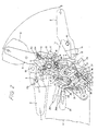
- the preferred embodiment of an automotive seat has a seat cushion A and a seat back B pivotably adjoined with the rear end of the seat cushion.
- a seat back adjusting mechanism C is provided between the seat cushion A and the seat back B for pivotally adjusting seat back position relative to the seat cushion.
- the seat back adjusting mechanism C includes a seat back reclining mechanism D for adjusting seat back angular position backward from a predetermined neutral position, and a walk-in seat back adjusting mechanism for permitting the seat back B to be tilted frontwardly from the neutral position.
- the seat back adjusting mechanism C further includes a double arm structure E for permitting the seat back B to be folded into a folded position, in which the back side of the seat back B is oriented substantially in horizontal as shown by phantom line. At the folded position, the back side of the seat back B can be used as table or luggage shelf for placing drink, food, luggage and so forth.
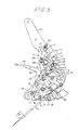
- the double arm structure E generally comprises a lower arm 2 and an upper arm 8 which is connected to the upper end of the lower arm in pivotal fashion.
- the lower arm 2 is associated with a seat back reclining mechanism D fixed on the rear end of a seat cushion frame which is not shown.
- the upper arm 8 is rigidly secured on a seat cushion frame which is not shown.
- the lower and upper arms 2 and 8 are normally locked for serving as an integrally formed arm.
- the upper arm 8 is pivotable with carrying the seat back B for placing the seat back to the folded position.
- a base plate 1 is rigidly secured onto the seat cushion frame supporting seat cushion A .
- the lower arm 2 is pivotably about a pivot shaft 3 which extends from from the base plate 1 .
- An arc shaped slot 4 is formed through the base plate 1 , through which a pin 5 projected from the lower arm 2 extends. Therefore, the pivotal movement of the lower arm 2 is guided and restricted by the arc shaped slot 4 .
- a spiral spring 6 is provided between the pivot shaft 3 and the pin 5 so as to normally bias the lower arm 2 in couterclockwise direction in Fig. 2 .
- the upper arm 8 is pivotably connected to the upper end of the lower arm 2 for pivotal movement about a pivot 9 .
- the upper arm 8 has a locking pin 10 in the vicinity of the lower end thereof.
- the locking pin 10 is engageable with a catching lever 11 which is pivotable about a pivot 12 .
- the catching lever 11 is normally biased in clockwise direction in Fig. 2 by means of a coil spring 13 which has one end connected to a projection 13a projecting from the upper arm 8 and a projection 13b projecting from the catching lever 11 .
- the catching lever 11 defines a locking pin receptable recess 14 for establishing locking engagement between the locking pin 10 and the catching lever 11 .
- the catching lever 11 is integrally formed with a lever section 15 which is oriented substantially perpendicular to the major section.
- a lock release lever 16 is pivotable about a shaft 17 and oriented in the vicinity of the catching lever 11 so that the lever may contact with the locking pin 10 .
- the lock release lever 16 has an upper edge 18 where it contact with the locking pin 10 and formed into arc shaped configuration.
- the lock release lever 16 has a bifurcated legs 19 and 19a .
- the lock release lever 16 is biased in counterclockwise direction by means of a torsional spring 20 .
- the leg 19a of the lock release lever 16 is associated with a walk-in lever 21 is pivotally supported by the pivot 3 for pivotal movement thereabout.
- the walk-in lever 21 has an integrally formed actuation lever section 22 which is oriented in opposition to the leg 19 of the lock release lever 16 .
- the walk-in lever 21 is connected to an actuation wire 23 which extends through a flexible guide tube 25 , end of which is secured to the seat cushion frame by means of a fastening bracket 24 . Through the actuation wire 23 , the walk-in lever 21 is connected to a walk-in mechanism F .
- An operation lever 26 is pivotable about the shaft 3 .
- the operation lever 26 has a lever section 28 which has one end mounted thereon a manual grouper handle 27 .
- the operation lever 26 is also provided with a foot pedal 29 .
- a return spring 30 is provided between the operation lever 26 and a holder plate 31 for biasing the operation lever in counterclockwise direction in Fig. 2 .
- a tooth member 32 is disposed between the base plate 1 and the holder plate 31 and pivotable about a pivot 33 .
- the tooth member 32 has a locking tooth 35 .
- the locking tooth 35 is designed for engagement with a locking tooth 34 formed on the outer periphery of the lower arm 2 .
- a pin 36 extends from a swing lever 43 and extends through an elongated opening 38 formed through the holder plate 31 .
- the pin 36 extends through an elongated opening 37 of the operation lever 26 .
- a cam member 39 is provided for pivotal movement about a shaft 40 on the base plate 1 .
- the cam member 39 is formed a leg 42 which is engageable with a recess 41 of the tooth member 32 .
- the swing lever 43 is connected with the cam member 39 via an emboss section 44 to be formed into crank shaped configuration as assembled together with the cam member 39 .
- the swing lever 43 is pivotable about a pivot 40 together with the cam member 39 .
- the pin 36 which extends though the elongated opening 37 is extended from the swing lever 43 .
- a link lever 45 is connected to the swing lever 43 via a connecting pin 46 at one end and has a contact pin 47 which contacts with the lever section 15 of the catching lever 11 .
- a link 48 is pivotally connected to the link lever 45 at one end and to the holder plate 31 at the other end.
- a stationary damper housing 50 is secured on the lower arm 2 .
- the stationary damper housing 50 serves as stopper for the pivot 12 of the catching lever 11 .
- a rubber damper 51 is housed within the stationary damper housing 50 .
- the rubber damper 51 is frictionally engageable with the side face of the upper arm 8 .
- An axis a extending through the pivot 12 of the catching lever 11 and the locking pin 10 , and an axis b extending through the locking pin 10 and the pivot 9 of the upper arm 8 intersects to reach other with an angle smaller than or equal to 90°.
- the walk-in mechanism F includes a seat slide rail 52 including a stationary rail rigidly secured on the floor of the vehicular body and a movable rail.
- a bracket 53 is secured on the movable rail.
- the bracket 53 supports a locking lever 56 which is biased by means of a spring 54 for locking engagement with one of a plurality of locking holes 55 formed through the stationary rail.
- the actuation wire 23 is connected to the free end of the locking lever 56 .
- a guide bracket 57 is provided for guiding the wire 23 so that the wire can be arranged in alignment with the locking lever 56 at least at the end thereof.
- the seat back reclining mechanism E can be operated through the operation lever 26 .
- the swing lever 43 is pivotally moved about the pivot 40 via the pin 36 .
- the cam member 39 which is integrated with the swing lever and engages the leg 42 with the recess 41 of the tooth member 32 , pivotally moves for causing clockwise rotation of the tooth member 32 about the pivot 33 .
- the locking engagement between teeth 34 and 35 is released.
- the lower arm 2 is permitted to pivot about the pivot 3 .
- the force of the spiral spring 6 becomes active for causing pivotal movement of the seat back B frontwardly.
- the seat back may stop frontward movement at the seat occupant back.
- the operation lever 26 By pushing the seat back B through the seat occupant back against the spring force, the seat can be tilted frontwardly for increasing reclining angle.
- the operation lever 26 By releasing the force pulling the operation lever 26 upwardly, the operation lever 26 is returned into initial position by the spring force of the spring 30 .
- the pin 36 causes clockwise pivotal movement of the swing lever 43 .
- the cam member 39 pivots in clockwise direction to release the keg 42 from the recess 41 of the tooth member 32 . Therefore, the tooth member 32 pivots in counterclockwise direction to cause engagement between teeth 34 and 35 . Therefore, the lower arm 2 is locked at the selected position.
- the seat back reclining mechanism permits reclining adjustment between the neutral position P and a fully reclined position Q .
- the operation lever 26 When walk-in mechanism F is to be used, the operation lever 26 is pulled upwardly or the foot pedal 29 . By this, the operation lever 26 is pivoted about the pivot 3 in clockwise direction. Accordingly, the locking engagement between the teeth 34 and 35 is release. Therefore, the lower arm 2 becomes free from the locking engagement. Therefore, the lower arm 2 is pivoted by means of the spiral spring 6 .
- the walk-in mechanism F since the walk-in mechanism F is operable in absence of the seat occupant, the lower arm 2 is inclined or tilted frontwardly.
- the pin 5 is pivotally moved along the arc shaped elongated slot 4 of the lower arm 2 .
- the lever section 15 of the swing lever comes into contact with the link lever 47 . This causes slight pivotal movement of the catching lever 11 about the pivot 12 in counterclockwise direction. Therefore, incomplete locking between the locking pin receptacle recess 14 of the catching lever 11 and the locking pin 10 is established.
- the operation lever 26 is initially pulled up to the uppermost position 26a as set forth above for causing frontward inclination.
- the link lever 45 is placed at a downwardly shifted position since it is depressed downwardly by the lever section 15 of the catching lever 11 .
- the operation lever 26 is operated to return into the half pulled-up position as represented by 26b .
- the swing lever 43 pivotally moved about the pivot 40 in clockwise direction.
- the link lever 45 shifts upwardly to push the the lever section 15 of the catching lever 11 by the contacting pin 47 .
- the catching lever 11 is pivoted in clounterclockwise direction. Therefore, the locking pin 10 and the locking pin receptable recess 14 of the catching lever 11 which are placed in incomplete engagement state by initially pulling the operation lever 26 in uppermost position 26a , are released. By this, the upper arm 8 becomes free to pivot about the pivot 9 .
- the catching lever 11 is designed for slight pivotal movement according to frontwardly tilting movement of the lower arm 2 and maintain the angle between the axes a and b smaller than or equal to 90° , the locking pin 10 becomes easily released from locking engagement with the catching lever 11 . Therefore, despite of the force exerted on the catching lever 11 for depressing the upper arm 8 onto the rubber damper 51 , the operational force required for releasing locking engagement between the locking pin 10 and the catching lever 11 becomes small.
- the upper arm 8 pivots about the pivot 9 in counterclockwise direction. Then, a pin 13a receiving one end of the coil spring 13 comes into engagement with the recess 2a of the lower arm 2 .
- the pin 13a and recess 2a engagement assures to maintain the seat back at the folded position, R in cooperation with the spring 13 .
- the locking pin 10 is shifted off the guide edge 18 of the lock release lever 16 which pushes the lever section 22 of the walk-in lever 21 .
- the lock release lever 16 is pivoted about the pivot 17 by means of the spring 20 in counterclockwise direction to place the leg 19a into contact with the pin 5 .
- the leg 19 is released from the lever section 22 of the walk-in lever 21 . Therefore, the walk-in lever 21 is forced into pivotal motion by the spring force of the spring 54 via the wire 23 , in clockwise direction. Therefore, the walk-in mechanism D is again placed into locking state. Therefore, the movable rail with the seat cushion is locked to the stationary lever at frontwardly shifted position. Therefore, the seat placed at the folded position can be stably maintained.
- the upper arm 8 with the seat back is pivoted in clockwise direction, as shown in Fig. 6 .
- the locking pin 10 comes into contact with the guide edge 18 of the lock release lever 16 to cause clockwise pivotal movement of the latter.
- the leg 19 of the lock release lever 16 again pushes the leg 22 of the walk-in lever 21 for causing counterclockwise pivotal movement about the pivot 3 of the walk-in lever.
- the actuation wire 23 is again pulled to release locking of the walk-in mechanism C .
- the locking pin 10 comes into engagement with the locking pin receptacle recess 14 of the catching lever 11 .
- the side face of the upper arm 8 comes into contact with the rubber damper 51 .
- the pin 13a shifts from the recess 2a for causing integrally locking of the lower and upper arms 2 and 8 .
- the movable rail of the seat slide 52 is shifted rearwardly on the stationary rail.
- the tilt angle of the seat back B is adjusted to the desired position in the manner discussed with respect to the operation of the seat back reclining mechanism.
- the tooth 35 of the tooth member 32 and the tooth 34 of the lower arm 2 comes into engagement. Therefore, the seat back B is fixedly maintained at the selected angular position as illustrated by P .
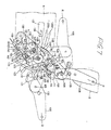
- Figs. 7 through 9 shows the second embodiment of the automotive seat structure, according to the present invention.
- a base plate 101 is rigidly secured onto the seat cushion frame supporting seat cushion A .
- the lower arm 102 is pivotably about a pivot shaft 103 which extends from from the base plate 101 .
- An arc shaped slot 104 is formed through the base plate 101 , though which a pin 105 projected from the lower arm 102 extends. Therefore, the pivotal movement of the lower arm 102 is guided and restricted by the arc shaped slot 104 .
- a spiral spring 106 is provided between the pivot shaft 103 and the pin 105 so as to normally bias the lower arm 102 in couterclockwise direction in Fig. 7 .
- the upper arm 108 is pivotably connected to the upper end of the lower arm 102 for pivotal movement about a pivot 109 .
- the upper arm 108 has a locking pin 110 in the vicinity of the lower end thereof.
- the locking pin 110 is engageable with a catching lever 111 which is pivotable about a pivot 112 .
- the catching lever 111 is normally biased in clockwise direction in Fig. 7 by means of a coil spring 113 which has one end connected to a projection 109 projecting from the upper arm 108 and a projection 113b projecting from the catching lever 111 .
- the catching lever 111 defines a locking pin receptable recess 114 for establishing locking engagement between the locking pin 110 and the catching lever 111 .
- the catching lever 111 is integrally formed with a lever section 115 which is oriented substantially perpendicular to the major section.
- the lever section 115 is formed with a pin 116 .
- the pin 116 is engageable with an elongated arc shaped opening 117 having arc radius centered at the pivot 112 of the lower arm 102 .
- a plate lever 119 is pivotable about the locking pin 110 of the upper arm 108 .
- the upper arm 108 has a stopper 120 projecting therefrom. The stopper 120 is designed to contact with the side edge of the lower arm 102 when the upper arm is tilted frontwardly.
- a walk-in lever 121 is pivotally supported by the pivot 103 for pivotal movement thereabout.
- the walk-in lever 121 has an integrally formed actuation lever section 122 which is oriented in opposition to the leg 119 of the lock release lever 116 .
- the walk-in lever 121 is connected to an actuation wire 123 which extends through a flexible guide tube 125 , end of which is secured to the seat cushion frame by means of a fastening bracket 124 .
- the walk-in lever 121 is connected to a walk-in mechanism F .
- An operation lever 126 is pivotable about the shaft 103 .
- the operation lever 126 has a lever section 128 which has one end mounted thereon a manual gripper handle 127 .
- the operation lever 126 is also provided with a foot pedal 129 .
- a return spring 130 is provided between the operation lever 126 and a holder plate 131 for biasing the operation lever in counterclockwise direction in Fig. 7 .
- a tooth member 132 is disposed between the base plate 101 and the holder plate 131 and pivotable about a pivot 133 .
- the tooth member 132 has a locking tooth 135 .
- the locking tooth 135 is designed for engagement with a locking tooth 134 formed on the outer periphery of the lower arm 102 .
- a pin 136 extends from a swing lever 143 and extends through an elongated opening 138 formed through the holder plate 131 . Furthermore, the pin 136 extends through an elongated opening 137 of the operation lever 126 .
- a cam member 139 is provided for pivotal movement about a shaft 140 on the base plate 101 .
- the cam member 139 is formed a leg 142 which is engageable with a recess 141 of the tooth member 132 .
- the swing lever 143 is connected with the cam member 139 via an emboss section 144 to be formed into crank shaped configuration as assembled together with the cam member 139 .
- the swing lever 143 is pivotable about a pivot 140 together with the cam member 139 .
- the pin 136 which extends though the elongated opening 137 is extended from the swing lever 143 .
- a swing lever 146 is pivotable with a common pivot of the tooth member 132 , at one end.
- the other end of the swing lever 146 is formed into a configuration adapted to contact with the pin 116 of the catching lever 111 .
- the swing lever 146 is formed with an elongated opening 148 which is engageable with a projection 149 on the operation lever 112 .
- a stationary damper housing 150 is secured on the lower arm 102 .
- the stationary damper housing 150 serves as stopper for the pivot 112 of the catching lever 111 .
- a rubber damper 151 is housed within the stationary damper housing 150 .
- the rubber damper 151 is frictionally engageable with the side face of the upper arm 108 .
- the seat back reclining mechanism E can be operated through the operation lever 126 .
- the swing lever 143 is pivotally moved about the pivot 140 via the pin 136 .
- the cam member 139 which is integrated with the swing lever and engages the leg 142 with the recess 141 of the tooth member 132 , pivotally moves for causing clockwise rotation of the tooth member 132 about the pivot 133 .
- the locking engagement between teeth 134 and 135 is released.
- the lower arm 102 is permitted to pivot about the pivot 103 .
- the force of the spiral spring 106 becomes active for causing pivotal movement of the seat back B frontwardly.
- the seat back may stop frontward movement at the seat occupant back.
- the seat can be tilted frontwardly for increasing reclining angle.
- the operation lever 126 is returned into initial position by the spring force of the spring 130 .
- the pin 136 causes clockwise pivotal movement of the swing lever 143 .
- the cam member 139 pivots in clockwise direction to release the keg 142 from the recess 141 of the tooth member 132 . Therefore, the tooth member 132 pivots in counterclockwise direction to cause engagement between teeth 134 and 135 . Therefore, the lower arm 102 is locked at the selected position.
- the seat back reclining mechanism permits reclining adjustment between the neutral position P and a fully reclined position Q .
- the operation lever 126 When walk-in mechanism F is to be used for permitting the rear seat passenger to pass therethrough, the operation lever 126 is pulled upwardly or the foot pedal 129 . By this, the operation lever 126 is pivoted about the pivot 310 in clockwise direction. Accordingly, the locking engagement between the teeth 134 and 135 is release. Therefore, the lower arm 102 becomes free from the locking engagement. Therefore, the lower arm 102 is pivoted by means of the spiral spring 106 . As can be appreciated, since the walk-in mechanism F is operable in absence of the seat occupant, the lower arm 102 is inclined or tilted frontwardly. At the same time, the pin 105 is pivotally moved along the arc shaped elongated slot 104 of the lower arm 102 .
- the plate lever 119 comes into contact with the lever section 122 of the walk-in lever 121 for causing latter to pivot in counterclockwise direction.
- the actuation wire 123 is pulled for a predetermined direction to pull the locking lever 56 in lock releasing position for causing frontward shifting the movable rail with the seat structure.
- the operation lever 126 is initially pulled up to the uppermost position 126a as set forth above for causing frontward inclination.
- the swing lever 146 is depressed by the pin 116 of the catching lever 111 so as to be maintained in counterclockwise pivoted position.
- the operation lever 126 is maintained to the uppermost position 126a .
- the pin 116 of the catching lever 111 comes into contact with the stopper 118 .
- the catching lever 11 is slightly pivoted in clounterclockwise direction.
- the catching lever 111 is designed for slight pivotal movement according to frontwardly tilting movement of the lower arm 102 and maintain the angle between the axes a and b smaller than or equal to 90° , the locking pin 110 becomes easily released from locking engagement with the catching lever 111 . Therefore, despite of the force exerted on the catching lever 111 for depressing the upper arm 108 onto the rubber damper 151 , the operational force required for releasing locking engagement between the locking pin 110 and the catching lever 111 becomes small.
- the upper arm 108 pivots about the pivot 109 in counterclockwise direction. Then, as shown by phantom line in Fig. 9 , the locking engagement between the plate lever 119 and the lever section 122 of the walk-in lever 121 is released. Therefore, the walk-in lever 121 is forced into pivotal motion by the spring force of the spring 154 via the wire 123 , in clockwise direction. Therefore, the walk-in mechanism D is again placed into locking state. Therefore, the movable rail with the seat cushion is locked to the stationary lever at frontwardly shifted position. Therefore, the seat placed at the folded position can be stably maintained.
- the upper arm 108 with the seat back is pivoted in clockwise direction, as shown in Fig. 7 .
- the locking pin 10 comes into engagement with the locking pin receptacle recess 114 of the catching lever 111 for causing integrally locking of the lower and upper arms 102 and 108 .
- the movable rail of the seat slide 152 is shifted rearwardly on the stationary rail.
- the tilt angle of the seat back B is adjusted to the desired position in the manner discussed with respect to the operation of the seat back reclining mechanism.
- the tooth 135 of the tooth member 132 and the tooth 134 of the lower arm 102 comes into engagement. Therefore, the seat back B is fixedly maintained at the selected angular position as illustrated by P .
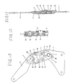
- Figs. 10 through 13 shows a seat back hinge structure which is applicable for pivotally supporting the seat back B on the seat cushion A at the side opposite to that where the preferred embodiments of the seat back adjusting mechanism is provided.
- a base plate 201 is rigidly fixed on the seat cushion frame.
- a lower arm 203 is pivotally mounted on the base plate 201 for pivotal movement about a pivot 202 .
- An upper arm 205 is pivotably connected to the upper end of the lower arm 203 via a pivot 204 .
- Upper and lower latches 211 and 213 are provided at upper and lower ends of the lower arm 203 .
- the upper latch 211 is pivotable about a pivot 210 .
- the lower latch 213 is pivotable about a pivot 212 .
- a link plate 216 is provided between the upper and lower latches 211 and 213 .
- the link plate 216 pivotable about pivot pins 214 and 215 respectively projecting from the upper and lower latches 211 and 213 .
- the upper arm 205 is formed with an extension 205a engageable with a recess 211a of the upper latch 211 .
- the lower latch 213 is formed with a recess 213a for receiving an extension 201a formed on the upper edge of the base plate 201 .
- the lower latch 213 .
- the lower latch 213 is designed to place the pivoting center for interengagement between the extension 201a and the recess 213a , and also the lower latch 213 may Figs. 10 and 13 .
- the lower latch 213 is normally biased in clockwise direction by means of a spring 217 .
- the upper latch 211 is formed with a cut-out 218 .
- An elastic member 219 such as rubber member, is secured in the cut-out 218 .
- the elastic member 219 is projected for frictionally contacting with the side face of the upper arm 205 .
- a stopper 220 is provided on the base plate 201 for limiting pivoting angular range of the lower arm 203 .
- the lower arm 203 is formed with a stopper projection 221 to abut against the stopper 220 .
- the whole structure of the hinge is covered by a holder 222 .
- the lower arm 203 when the seat back B is operated into the folded position, the lower arm 203 follows pivotal movement of the seat back to be pivoted about the pivot 202 in counterclockwise direction in Figs. 10 and 13 . Pivotal movement of the lower arm 203 is limited by the abutting of the stopper projection 221 onto the stopper 220 .
- the lower latch 213 slides on the guide edge 208 of the base plate 201 to establish engagement between the extension 201a and the recess 213a .
- the lower latch 213 pivot about the pivot 212 .
- the link plate 216 drives the upper latch 211 in clockwise direction about the pivot 210 .
- engagement between the recess 211a and the extension 205a is released. Therefore, the upper arm 205 is pivoted about the pivot 204 to be placed at substantially horizontal position.
- the seat back is pulled in clockwise direction.
- the extension 205a of the upper arm 205 comes into engagement with the recess 211a of the upper latch 211 . Therefore, the upper latch 211 pivots about the pivot 210 in counterclockwise direction.
- the lower latch 213 is driven to pivot in counterclockwise about the pivot 212 via the link plate 216 .
- the extension 201a of the base place 201 is released from the recess 213a of the lower latch 213 . Therefore, the lower latch 213 becomes movable along the guide edge 208 on the base plate 201 . Therefore, the seat back is maintained at the desired reclining position.
Landscapes
- Engineering & Computer Science (AREA)
- Aviation & Aerospace Engineering (AREA)
- Transportation (AREA)
- Mechanical Engineering (AREA)
- Seats For Vehicles (AREA)
- Chairs For Special Purposes, Such As Reclining Chairs (AREA)
Applications Claiming Priority (6)
| Application Number | Priority Date | Filing Date | Title |
|---|---|---|---|
| JP19560589A JPH0787804B2 (ja) | 1989-07-28 | 1989-07-28 | 二段折れリクライナー |
| JP195605/89 | 1989-07-28 | ||
| JP8878689U JPH0741389Y2 (ja) | 1989-07-28 | 1989-07-28 | リクライナー用ヒンジ |
| JP195606/89 | 1989-07-28 | ||
| JP88786/89 | 1989-07-28 | ||
| JP19560689A JPH0787805B2 (ja) | 1989-07-28 | 1989-07-28 | 二段折れリクライナー |
Publications (3)
| Publication Number | Publication Date |
|---|---|
| EP0410814A2 true EP0410814A2 (de) | 1991-01-30 |
| EP0410814A3 EP0410814A3 (en) | 1991-11-13 |
| EP0410814B1 EP0410814B1 (de) | 1995-09-13 |
Family
ID=27305908
Family Applications (1)
| Application Number | Title | Priority Date | Filing Date |
|---|---|---|---|
| EP90308325A Expired - Lifetime EP0410814B1 (de) | 1989-07-28 | 1990-07-30 | Kraftfahrzeugsitz mit einem Mechanismus zum Erleichtern des Zugangs |
Country Status (3)
| Country | Link |
|---|---|
| EP (1) | EP0410814B1 (de) |
| DE (1) | DE69022327T2 (de) |
| ES (1) | ES2079443T3 (de) |
Cited By (10)
| Publication number | Priority date | Publication date | Assignee | Title |
|---|---|---|---|---|
| EP0512517A1 (de) * | 1991-05-10 | 1992-11-11 | FUJI KIKO CO., Ltd. | Sitz-Umklappvorrichtung |
| WO1999038723A1 (en) * | 1998-01-28 | 1999-08-05 | Bertrand Faure Components Ltd. | Rotary recliner control mechanism for multifunction vehicle seat applications |
| FR2799420A1 (fr) * | 1999-10-08 | 2001-04-13 | Faure Bertrand Equipements Sa | Siege de vehicule |
| FR2800021A1 (fr) * | 1999-10-26 | 2001-04-27 | Faure Bertrand Equipements Sa | Siege de vehicule comportant un dossier basculable vers l'avant avec une commande a rattrapage de jeux |
| FR2804386A1 (fr) * | 2000-02-02 | 2001-08-03 | Faure Bertrand Equipements Sa | Siege de vehicule comportant un dossier rabattable vers l'avant |
| FR2820695A1 (fr) * | 2001-02-15 | 2002-08-16 | Faurecia Sieges Automobile | Siege de vehicule dote d'un dossier rabattable |
| GB2379384A (en) * | 2001-09-07 | 2003-03-12 | Johnson Controls Tech Co | Foldable seat |
| FR2850913A1 (fr) * | 2003-02-12 | 2004-08-13 | Faurecia Sieges Automobile | Siege de vehicule automobile comportant un dossier basculable vers l'avant |
| US6880888B2 (en) | 2001-03-31 | 2005-04-19 | Keiper Gmbh & Co. Kg | Fitting for a vehicle seat |
| GB2586163A (en) * | 2019-08-09 | 2021-02-10 | Ford Global Tech Llc | A Seat for a vehicle |
Families Citing this family (2)
| Publication number | Priority date | Publication date | Assignee | Title |
|---|---|---|---|---|
| DE10310424B4 (de) * | 2003-03-11 | 2008-01-03 | Faurecia Autositze Gmbh | Kraftfahrzeugsitz |
| DE102010023765B4 (de) | 2009-08-05 | 2018-04-26 | Adient Luxembourg Holding S.À R.L. | Verfahren zur Überführung einer Rückenlehne von der Gebrauchs- in eine Verstaustellung und Kraftfahrzeugsitz |
Family Cites Families (3)
| Publication number | Priority date | Publication date | Assignee | Title |
|---|---|---|---|---|
| DE2317926C3 (de) * | 1973-04-10 | 1979-08-30 | Maschinenfabrik Augsburg-Nuernberg Ag, 8000 Muenchen | Kippbarer, in seiner Gebrauchslage mittels einer Verriegelungsvorrichtung festlegbarer Fahrzeugsitz |
| JPS5330530A (en) * | 1976-08-30 | 1978-03-22 | Aisin Seiki Co Ltd | Device for reclining automotive seat |
| JPS57110535A (en) * | 1980-12-26 | 1982-07-09 | Nissan Motor Co Ltd | Walk-in device for seat of vehicle |
-
1990
- 1990-07-30 DE DE1990622327 patent/DE69022327T2/de not_active Expired - Fee Related
- 1990-07-30 ES ES90308325T patent/ES2079443T3/es not_active Expired - Lifetime
- 1990-07-30 EP EP90308325A patent/EP0410814B1/de not_active Expired - Lifetime
Cited By (14)
| Publication number | Priority date | Publication date | Assignee | Title |
|---|---|---|---|---|
| EP0512517A1 (de) * | 1991-05-10 | 1992-11-11 | FUJI KIKO CO., Ltd. | Sitz-Umklappvorrichtung |
| WO1999038723A1 (en) * | 1998-01-28 | 1999-08-05 | Bertrand Faure Components Ltd. | Rotary recliner control mechanism for multifunction vehicle seat applications |
| US6464299B1 (en) | 1999-10-08 | 2002-10-15 | Faurecia Sieges D'automobile S.A. | Vehicle seat |
| FR2799420A1 (fr) * | 1999-10-08 | 2001-04-13 | Faure Bertrand Equipements Sa | Siege de vehicule |
| FR2800021A1 (fr) * | 1999-10-26 | 2001-04-27 | Faure Bertrand Equipements Sa | Siege de vehicule comportant un dossier basculable vers l'avant avec une commande a rattrapage de jeux |
| FR2804386A1 (fr) * | 2000-02-02 | 2001-08-03 | Faure Bertrand Equipements Sa | Siege de vehicule comportant un dossier rabattable vers l'avant |
| FR2820695A1 (fr) * | 2001-02-15 | 2002-08-16 | Faurecia Sieges Automobile | Siege de vehicule dote d'un dossier rabattable |
| US6880888B2 (en) | 2001-03-31 | 2005-04-19 | Keiper Gmbh & Co. Kg | Fitting for a vehicle seat |
| GB2379384A (en) * | 2001-09-07 | 2003-03-12 | Johnson Controls Tech Co | Foldable seat |
| GB2379384B (en) * | 2001-09-07 | 2005-02-16 | Johnson Controls Tech Co | Foldable seat |
| FR2850913A1 (fr) * | 2003-02-12 | 2004-08-13 | Faurecia Sieges Automobile | Siege de vehicule automobile comportant un dossier basculable vers l'avant |
| US7036885B2 (en) | 2003-02-12 | 2006-05-02 | Faurecia Sieges D'automobile | Motor vehicle seat including a seat back that can be tilted forwards |
| GB2586163A (en) * | 2019-08-09 | 2021-02-10 | Ford Global Tech Llc | A Seat for a vehicle |
| GB2586163B (en) * | 2019-08-09 | 2021-09-01 | Ford Global Tech Llc | A seat for a vehicle |
Also Published As
| Publication number | Publication date |
|---|---|
| EP0410814B1 (de) | 1995-09-13 |
| DE69022327D1 (de) | 1995-10-19 |
| DE69022327T2 (de) | 1996-02-29 |
| EP0410814A3 (en) | 1991-11-13 |
| ES2079443T3 (es) | 1996-01-16 |
Similar Documents
| Publication | Publication Date | Title |
|---|---|---|
| US4268086A (en) | Seat assembly for an automobile | |
| US5052750A (en) | Tiltable auxiliary chair having locking means and pivotal seat belt engagement plate for forward and rearward facing | |
| US5531503A (en) | Vehicle seat track assembly | |
| US5104189A (en) | Reclining seat for motor vehicle | |
| EP4222019B1 (de) | Basisstruktur für einen sitzkörper eines kindersicherheitssitzes | |
| EP0410814A2 (de) | Kraftfahrzeugsitz mit einem Mechanismus zum Erleichtern des Zugangs | |
| US20040051361A1 (en) | Motor vehicle seat | |
| US6698835B2 (en) | Seat support mechanism of vehicles | |
| JP2005153874A (ja) | 自動車シート | |
| KR20050049556A (ko) | 플로어 격납 자동 시트 조립체 | |
| JP4266633B2 (ja) | 自動車の内壁用の調節可能なアームレスト | |
| EP1500550B1 (de) | Sitzvorrichtung | |
| US4801177A (en) | Reclining device of seat | |
| US5609392A (en) | Integrated child seat | |
| JP4260570B2 (ja) | 車両用シート装置 | |
| JPH0360604A (ja) | 二段折れリクライナー | |
| JPH0360603A (ja) | 二段折れリクライナー | |
| JPH024819Y2 (de) | ||
| JPH0346971Y2 (de) | ||
| JPS6232912Y2 (de) | ||
| JP2002316564A (ja) | 自動車用シート装置 | |
| JPH07108636B2 (ja) | ウオークイン機構を備えた二段折れリクライナー | |
| JPS6310984Y2 (de) | ||
| JP2002225598A (ja) | 自動車用シート | |
| CN120156409A (zh) | 儿童安全座椅 |
Legal Events
| Date | Code | Title | Description |
|---|---|---|---|
| PUAI | Public reference made under article 153(3) epc to a published international application that has entered the european phase |
Free format text: ORIGINAL CODE: 0009012 |
|
| AK | Designated contracting states |
Kind code of ref document: A2 Designated state(s): DE ES FR GB |
|
| PUAL | Search report despatched |
Free format text: ORIGINAL CODE: 0009013 |
|
| AK | Designated contracting states |
Kind code of ref document: A3 Designated state(s): DE ES FR GB |
|
| 17P | Request for examination filed |
Effective date: 19920505 |
|
| 17Q | First examination report despatched |
Effective date: 19940426 |
|
| GRAA | (expected) grant |
Free format text: ORIGINAL CODE: 0009210 |
|
| AK | Designated contracting states |
Kind code of ref document: B1 Designated state(s): DE ES FR GB |
|
| REF | Corresponds to: |
Ref document number: 69022327 Country of ref document: DE Date of ref document: 19951019 |
|
| REG | Reference to a national code |
Ref country code: ES Ref legal event code: FG2A Ref document number: 2079443 Country of ref document: ES Kind code of ref document: T3 |
|
| ET | Fr: translation filed | ||
| PGFP | Annual fee paid to national office [announced via postgrant information from national office to epo] |
Ref country code: FR Payment date: 19960709 Year of fee payment: 7 |
|
| PLBE | No opposition filed within time limit |
Free format text: ORIGINAL CODE: 0009261 |
|
| STAA | Information on the status of an ep patent application or granted ep patent |
Free format text: STATUS: NO OPPOSITION FILED WITHIN TIME LIMIT |
|
| PGFP | Annual fee paid to national office [announced via postgrant information from national office to epo] |
Ref country code: GB Payment date: 19960722 Year of fee payment: 7 |
|
| PGFP | Annual fee paid to national office [announced via postgrant information from national office to epo] |
Ref country code: ES Payment date: 19960729 Year of fee payment: 7 |
|
| PGFP | Annual fee paid to national office [announced via postgrant information from national office to epo] |
Ref country code: DE Payment date: 19960802 Year of fee payment: 7 |
|
| 26N | No opposition filed | ||
| PG25 | Lapsed in a contracting state [announced via postgrant information from national office to epo] |
Ref country code: GB Free format text: LAPSE BECAUSE OF NON-PAYMENT OF DUE FEES Effective date: 19970730 |
|
| PG25 | Lapsed in a contracting state [announced via postgrant information from national office to epo] |
Ref country code: ES Free format text: LAPSE BECAUSE OF THE APPLICANT RENOUNCES Effective date: 19970731 |
|
| GBPC | Gb: european patent ceased through non-payment of renewal fee |
Effective date: 19970730 |
|
| PG25 | Lapsed in a contracting state [announced via postgrant information from national office to epo] |
Ref country code: FR Free format text: LAPSE BECAUSE OF NON-PAYMENT OF DUE FEES Effective date: 19980331 |
|
| PG25 | Lapsed in a contracting state [announced via postgrant information from national office to epo] |
Ref country code: DE Free format text: LAPSE BECAUSE OF NON-PAYMENT OF DUE FEES Effective date: 19980401 |
|
| REG | Reference to a national code |
Ref country code: FR Ref legal event code: ST |
|
| REG | Reference to a national code |
Ref country code: ES Ref legal event code: FD2A Effective date: 20001102 |