EP0410864B1 - Schliessblech, z.B. für Kraftfahrzeugflügel - Google Patents
Schliessblech, z.B. für Kraftfahrzeugflügel Download PDFInfo
- Publication number
- EP0410864B1 EP0410864B1 EP19900402113 EP90402113A EP0410864B1 EP 0410864 B1 EP0410864 B1 EP 0410864B1 EP 19900402113 EP19900402113 EP 19900402113 EP 90402113 A EP90402113 A EP 90402113A EP 0410864 B1 EP0410864 B1 EP 0410864B1
- Authority
- EP
- European Patent Office
- Prior art keywords
- plates
- lock
- staple according
- plate
- lock staple
- Prior art date
- Legal status (The legal status is an assumption and is not a legal conclusion. Google has not performed a legal analysis and makes no representation as to the accuracy of the status listed.)
- Expired - Lifetime
Links
- 210000002105 tongue Anatomy 0.000 claims description 14
- 239000000463 material Substances 0.000 claims description 5
- 230000000694 effects Effects 0.000 claims description 3
- 230000000903 blocking effect Effects 0.000 claims description 2
- 230000001747 exhibiting effect Effects 0.000 claims 1
- BASFCYQUMIYNBI-UHFFFAOYSA-N platinum Chemical compound [Pt] BASFCYQUMIYNBI-UHFFFAOYSA-N 0.000 description 5
- 238000009434 installation Methods 0.000 description 1
- 230000014759 maintenance of location Effects 0.000 description 1
- 230000000284 resting effect Effects 0.000 description 1
- 230000000717 retained effect Effects 0.000 description 1
Images

Classifications
-
- E—FIXED CONSTRUCTIONS
- E05—LOCKS; KEYS; WINDOW OR DOOR FITTINGS; SAFES
- E05B—LOCKS; ACCESSORIES THEREFOR; HANDCUFFS
- E05B15/00—Other details of locks; Parts for engagement by bolts of fastening devices
- E05B15/02—Striking-plates; Keepers; Bolt staples; Escutcheons
- E05B15/0205—Striking-plates, keepers, staples
- E05B15/024—Striking-plates, keepers, staples adjustable
- E05B15/0245—Movable elements held by friction, cooperating teeth, or the like
-
- E—FIXED CONSTRUCTIONS
- E05—LOCKS; KEYS; WINDOW OR DOOR FITTINGS; SAFES
- E05B—LOCKS; ACCESSORIES THEREFOR; HANDCUFFS
- E05B15/00—Other details of locks; Parts for engagement by bolts of fastening devices
- E05B15/02—Striking-plates; Keepers; Bolt staples; Escutcheons
- E05B15/0205—Striking-plates, keepers, staples
- E05B15/024—Striking-plates, keepers, staples adjustable
- E05B2015/027—Striking-plates, keepers, staples adjustable auto-adjustable
-
- E—FIXED CONSTRUCTIONS
- E05—LOCKS; KEYS; WINDOW OR DOOR FITTINGS; SAFES
- E05B—LOCKS; ACCESSORIES THEREFOR; HANDCUFFS
- E05B15/00—Other details of locks; Parts for engagement by bolts of fastening devices
- E05B15/02—Striking-plates; Keepers; Bolt staples; Escutcheons
- E05B15/0205—Striking-plates, keepers, staples
- E05B15/024—Striking-plates, keepers, staples adjustable
- E05B2015/0275—Striking-plates, keepers, staples adjustable in two directions
Definitions
- the present invention relates generally to a lock for locking a door leaf, such as for example the leaf forming a tailgate of a motor vehicle.
- Lock strikes have already been proposed for a leaf of a motor vehicle for example, essentially comprising a sole which is integral with a part having the general shape of a U on which a bolt, hook or the like can be hung when the leaf closes. .
- the sole was generally provided with buttonholes allowing the adjustment of the U-shaped part with respect to the sole, so as to ensure correct locking when the leaf is closed.
- the adjustment of the U-piece relative to the base was done by approximation and was relatively long and not very precise due to the fact that the adjustment in one direction often modified the adjustment in the other direction. It follows that several adjustments had to be made, which required several opening and closing of the door leaf.
- the present invention aims to remedy these drawbacks by proposing a self-adjusting lock keeper, that is to say with automatic and positive adjustment by a single closing action of the door leaf, which represents a significant time savings and also allows the installation of door leaves previously and fully garnished.
- the subject of the invention is a lock keeper for a door leaf of a motor vehicle for example and of the type comprising a sole to which is attached a part having the general shape of a U on which can be hooked a bolt, hook or the like, characterized in that the two branches of the U of the attachment piece are bent in two planes perpendicular to the pivot axis of the leaf, and the sole consists of two plates between which the two can be slidably mounted beforehand curved branches of the U to allow self-positioning of this U under the effect of closing the leaf, while means are provided for elastically tightening the plates in order to achieve self-positioning of the U and to perform, after this self-positioning, the blocking of the U between the two plates and the fixing of these plates.
- the two plates are assembled using at least one rod, preferably cylindrical, cooperating with tongues integral with one of the edges of the two plates.
- the rod is preferably made of an elastically deformable material, rubber or similar material.
- One of the plates has at least one lug for hooking this plate into an opening in the other plate.
- one of the plates has on its two opposite edges an arcuate tongue capable of receiving the two curved branches of the U forming the attachment part of the aforementioned bolt or hook.
- the plate located below that comprising the aforementioned arcuate tongues is provided with bosses on which the curved branches of the U can bear.
- each curved branch of the U carries at its free end a lug or the like.
- the two plates are each provided with an orifice, preferably oblong, capable of receiving a threaded element allowing the elastic clamping and fixing of these plates with the U-shaped attachment part on the body of a vehicle for example.
- this keeper there is provision, on either side of the orifice of the plate comprising the above-mentioned bosses, an elongated opening receiving the curved branches of the U.
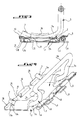
- a lock keeper in accordance with this invention essentially comprises three parts, namely a first plate or lower plate 1, a second plate, or upper plate 2, and a generally U-shaped attachment piece 3 retained between the two plates 1 and 2.
- rod 4 preferably cylindrical, made of rubber or similar material and which in a way forms an elastically deformable key.
- All of the above parts forming the keeper can be maintained and fixed on, for example, the floor of a vehicle by a screw 5 provided with a captive washer 6, as can be seen in FIG. 1.
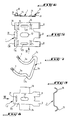
- the U-shaped attachment part 3 as can be seen in FIGS. 4 and 7 in particular, comprises two branches 3a which are bent in two planes substantially parallel and perpendicular to the pivot axis of the leaf (not shown), this axis being parallel to the axis of the cylindrical rod or key 4.
- These two curved or arcuate branches 3a are connected by a part 3b forming in a way a bar on which the bolt or hook of the lock will hang.
- the strip 3b itself has somewhat the shape of a U, the base of which is formed by the strip 3b itself and whose branches 3c are connected to the curved branches 3a.
- the lower plate 1 has on one of its edges a plurality of deformed tongues 8 which cooperate with tongues 9 projecting from one edge of the upper plate 2 to receive the rod or key 4, as can be seen on the Figures 1 to 4.
- the tongues 8 and 9 are interposed and nested so that the rod or key 4 can retain the plates 1 and 2 one against each other.
- the lower plate 1 has on its edge opposite to that carrying the tongues 8, a tab 10 projecting upwards, as can be seen in FIG. 4, and hooking in an opening 11 provided in the upper plate 2.
- the lower plate 1 In its center, and as can be seen in FIG. 5, the lower plate 1 has an oblong orifice 12 on either side of which there is an elongated opening 13 capable of guiding the curved branches 3a of the part d to slide. 'hanging 3 in general U shape.
- the lower plate 1 also comprises four bosses 14 located substantially at the four corners of said plate, the elongated opening 13 on either side of the orifice 12 being located between two bosses, as can be seen in FIG. 5.
- the upper plate 2 as can be seen in Figures 8 and 9, comprises, in addition to the opening 11 formed in a lug 15, and in addition to the tongues 9 which are two in number, two arcuate and opposite tongues 16 which are able to receive the two curved branches 3a of the U forming the attachment part 3.
- an oblong orifice 17 capable of coming into correspondence with the oblong orifice 12 of the lower plate 1 so as to allow the passage of the screw 5 previously mentioned.
- the tab 15 of the plate 2 comprising the opening 11 is inserted between two raised tabs 18 of the plate 1, these two raised tabs 18 being located on either side of the latching tab 10 previously mentioned.
- the keeper constituted by the two plates 1, 2 and by the U-shaped attachment piece 3 forms a whole assembled by the rod or key 4 and by the attachment tab 10.
- This assembly is fixed to the vehicle floor using the screw 5, and this in a relatively loose manner to leave the U-shaped part 3 the possibility of sliding by its branches 3a between the plates 1 and 2, that is to say, more precisely, in the arcuate tongues 16 of the plate 2 and resting on the bosses 14 of the plate 1.
- the boot flap is then closed with sufficient force so as to allow the U-piece 3 to slide and the seal of the boot flap or tailgate to be compressed. Then, we open the tailgate, and we will be sure that the U-shaped part 3 will be in the correct position for hooking the bolt or hook secured to the leaf, and allowing the crushing of the seal surrounding the bay. Then, the tightening of the screw 5 which was in a way an elastic tightening of the two plates 1 and 2 is completed, so as to block the keeper on the floor of the vehicle.
- the keeper according to this invention avoids the numerous adjustments and manipulations of the leaf of the U-shaped part of the keeper, since, from the first closing of the leaf, the self-positioning of the attachment part will be carried out.
- U of the strike thanks to two simultaneous movements of this part, namely a sliding or sliding in one direction and a tilting in the other.
- the keeper of this invention thanks to the simplicity of its adjustment, allows a significant saving of assembly time, requires only one operator and allows the use of fully furnished door leaves.
Landscapes
- Lock And Its Accessories (AREA)
Claims (9)
- Schlossraste zum Beispiel für Kraftfahrzeugstürflügel und der eine Schlenplatte aufweisenden Gattung, mit welcher ein die allgemeine Gestalt eines Us aufweisendes Stück (3) an welchem sich ein Riegel, Haken oder dergleichen anhaken kann, fest verbunden ist, dadurch gekennzeichnet, dass die beiden Schenkel (3a) des Us des Verhakungstückes (3) in zwei senkrecht zur Schwenkachse des Türflügels verlaufenden Ebenen umgebogen sind und die Sohlenplatte aus zwei Platten (1,2) besteht, zwischen welchen die beiden umgebogenen Schenkel (3a) des Us vorher gleitbar angeordnet werden können, um ein Selbstpositionieren des Us unter der Wirkung des Schliessens des Türflügels zu gestatten, während Mittel vorgesehen sind, um die Platten (1, 2) elastisch anzudrücken zum Zweck der Durchführung des vorgenannten Selbstpositionieren des Us und um, nach diesem Selbstpositionieren, das Festsetzen des Us zwischen den beiden Platten (1, 2) und die Befestigung des besagten Platten durchzuführen.
- Schlossraste nach Anspruch 1, dadurch gekennzeichnet, dass die beiden Platten (1,2) mit Hilfe wenigstens eines vorzugsweise zylindrischen, mit, mit einem der Ränder der beiden Platten fest befestigten Zungen (8,9) zusammenwirkenden Stiftes (4) zusammengefügt sind.
- Schlossraste nach Anspruch 2, dadurch gekennzeichnet, dass der Stift (4) aus einem elastische verformbaren Werkstoff, Gummi oder ähnlichen Werkstoff hergestellt ist.
- Schlossraste Nach Anspruch 1 oder 3, dadurch gekennzeichnet, dass eine (1) der Platten wenigstens eine Pratze (10) zum Anhaken dieser Plante in einer Oeffnung (12) der anderen Platte aufweist.
- Schlossraste nach einem der Ansprüche 1 bis 4, dadurch gekennzeichnet, dass eine (2) der Platten an zwei entgegengesetzen Rändern eine bogenförmige Zunge (16) aufweist, die fähig ist, die beiden umgebogenen Schenkel (3a) des das U bildenden vorgenannten Verhakungsstückes (3) aufzunehmen.
- Schlossraste nach einem der Ansprüche 1 bis 5, dadurch gekennzeichnet, dass die unterhalb der die vorgenannten bogenförmigen Zungen (16) aufweisenden Platte (2) gelegene Platte (1) mit Dellen (14) versehen ist, an welchen sich die umgebogenen Schenkel (3a) des Us abstützen können.
- Schlossraste nach einem der Ansprüche 1 bis 6, dadurch gekennzeichnet, dass jeder umgebogene Schenkel (3a) des Us an seinem freien Ende einen Nocken (7) trägt.
- Schlossraste nach einem der Ansprüche 1 bis 7, dadurch gekennzeichnet, dass die beiden Platten (1, 2) jeweils in ihrer Mitte mit einer vorzugsweise länglichen Oeffnung (12, 17) versehen sind, die fähig ist, ein das elastische Anziehen und die Befestigung dieser Platten mit dem U-förmigen Verhakungsstück (3) zum Beispiel an dem Kasten eines Fahrzeugs gestattendes Gewindeelement (5) aufzunehmen.
- Schlossraste nach einem der Ansprüche 1 bis 8, dadurch gekennzeichnet, dass beiderseits der Oeffnung (12) der die vorgenannten Dellen (14) aufweisenden Platte (1) eine die umgebogenen Schenkel (3a) des Us aufnehmende langgestreckte Oeffnung (13) vorgessehen ist.
Applications Claiming Priority (2)
| Application Number | Priority Date | Filing Date | Title |
|---|---|---|---|
| FR8910076A FR2650325B1 (fr) | 1989-07-26 | 1989-07-26 | Gache de serrure pour battant de vehicule automobile par exemple |
| FR8910076 | 1989-07-26 |
Publications (2)
| Publication Number | Publication Date |
|---|---|
| EP0410864A1 EP0410864A1 (de) | 1991-01-30 |
| EP0410864B1 true EP0410864B1 (de) | 1993-02-03 |
Family
ID=9384163
Family Applications (1)
| Application Number | Title | Priority Date | Filing Date |
|---|---|---|---|
| EP19900402113 Expired - Lifetime EP0410864B1 (de) | 1989-07-26 | 1990-07-23 | Schliessblech, z.B. für Kraftfahrzeugflügel |
Country Status (3)
| Country | Link |
|---|---|
| EP (1) | EP0410864B1 (de) |
| DE (1) | DE69000865T2 (de) |
| FR (1) | FR2650325B1 (de) |
Families Citing this family (9)
| Publication number | Priority date | Publication date | Assignee | Title |
|---|---|---|---|---|
| FR2695424B1 (fr) * | 1992-09-10 | 1994-11-04 | Vachette Ymos | Dispositif de gâche réglable. |
| FR2706938A1 (en) * | 1993-06-25 | 1994-12-30 | Coutier Moulage Gen Ind | Adjustable keeper for a motor-vehicle body lock |
| DE10322356B4 (de) * | 2003-05-17 | 2006-12-21 | BÖCO Böddecker & Co. GmbH & Co. KG | Einstellbarer Schließbolzen |
| KR100999157B1 (ko) | 2008-11-07 | 2010-12-08 | 현대자동차주식회사 | 차량의 후드 스트라이커 조립체 |
| FR2952899B1 (fr) * | 2009-11-23 | 2011-12-16 | Peugeot Citroen Automobiles Sa | Renfort de fixation destine a etre monte sur une structure de vehicule automobile et a permettre la fixation d'une piece rapportee. |
| JP6242617B2 (ja) * | 2013-07-12 | 2017-12-06 | 株式会社タチエス | 車両用ストライカ |
| DE102019102392A1 (de) * | 2019-01-30 | 2020-07-30 | Bayerische Motoren Werke Aktiengesellschaft | Schließbügel für ein Kraftfahrzeug-Karosserieschloss, Kraftfahrzeug-Karosserieschloss mit einem solchen Schließbügel sowie entsprechend ausgestattetes Kraftfahrzeug |
| DE102019102393A1 (de) | 2019-01-30 | 2020-07-30 | Bayerische Motoren Werke Aktiengesellschaft | Schließbügel für ein Kraftfahrzeug-Karosserieschloss, Kraftfahrzeug-Karosserieschloss mit einem solchen Schließbügel sowie entsprechend ausgestattetes Kraftfahrzeug |
| DE102019102391A1 (de) | 2019-01-30 | 2020-07-30 | Bayerische Motoren Werke Aktiengesellschaft | Schließbügel für ein Kraftfahrzeug-Karosserieschloss, Kraftfahrzeug-Karosserieschloss mit einem solchen Schließbügel sowie entsprechend ausgestattetes Kraftfahrzeug |
Family Cites Families (3)
| Publication number | Priority date | Publication date | Assignee | Title |
|---|---|---|---|---|
| FR2589188B3 (fr) * | 1985-10-29 | 1988-02-19 | Renault | Serrure pour battant de vehicule automobile |
| FR2606064B1 (fr) * | 1986-10-31 | 1990-06-08 | Renault | Gache de serrure pour un battant de vehicule automobile |
| US4756565A (en) * | 1987-01-12 | 1988-07-12 | General Motors Corporation | Striker assembly |
-
1989
- 1989-07-26 FR FR8910076A patent/FR2650325B1/fr not_active Expired - Fee Related
-
1990
- 1990-07-23 EP EP19900402113 patent/EP0410864B1/de not_active Expired - Lifetime
- 1990-07-23 DE DE1990600865 patent/DE69000865T2/de not_active Expired - Fee Related
Also Published As
| Publication number | Publication date |
|---|---|
| FR2650325A1 (fr) | 1991-02-01 |
| FR2650325B1 (fr) | 1991-11-29 |
| DE69000865T2 (de) | 1993-08-19 |
| EP0410864A1 (de) | 1991-01-30 |
| DE69000865D1 (de) | 1993-03-18 |
Similar Documents
| Publication | Publication Date | Title |
|---|---|---|
| EP0075501B1 (de) | Bindestreifen | |
| EP0681110B1 (de) | Verbesserte Käfigmutter | |
| EP0169772A1 (de) | Klammer zum Verbinden von Stücken, zum Beispiel von Platten | |
| EP0780582A1 (de) | Befestigungs- oder Verschlussvorrichtung mit Überschreitung eines toten Punktes | |
| EP0410864A1 (de) | Schliessblech, z.B. fÀ¼r Kraftfahrzeugflügel | |
| FR2754576A1 (fr) | Ecrou a montage par clippage sur un profile | |
| FR2579693A1 (fr) | Goujon a souder et agrafe se montant sur ce goujon | |
| FR2776721A1 (fr) | Fixation glissante d'une piece en matiere plastique sur un support | |
| FR2544266A1 (fr) | Profile de recouvrement pour une gouttiere emboitee dans un toit de vehicule, pour la reception et la fixation des pieds d'appui d'une galerie de toit | |
| FR2618478A1 (fr) | Capuchon de recouvrement pour une charniere de meuble | |
| FR2732716A1 (fr) | Charniere pour volets de recouvrement dans des vehicules automobiles | |
| JPS62500601A (ja) | ヒンジ | |
| FR2684147A1 (fr) | Attache de fixation d'une piece munie d'une tige sur une paroi. | |
| EP0744316A1 (de) | Verriegelungsvorrichtung für eine Zahnstange | |
| EP1957733B1 (de) | Provisorische Verriegelungsvorrichtung | |
| EP0742329B1 (de) | Verriegelungsvorrichtung für Kraftwagenflügel mit verbesserten Einbaumitteln für Verkleidungskappe | |
| EP1087066B1 (de) | Anordnung zur Befestigung eines Einbauelementes in einer Öffnung einer Trägerplatte | |
| EP0187587B1 (de) | Vorrichtung zum Offenhalten einer Tür | |
| FR2626329A1 (fr) | Ecrou en forme de pince et assemblage realise a l'aide de cet ecrou | |
| EP0860616B1 (de) | Befestigungsvorrichtung eines Bauteils auf einem Träger | |
| FR2665304A1 (fr) | Borne d'alimentation electrique. | |
| FR3010116A1 (fr) | Gache destinee a cooperer avec la serrure d'un ouvrant de vehicule automobile | |
| FR2589188A1 (fr) | Serrure pour battant de vehicule automobile | |
| FR2597915A1 (fr) | Charniere degondable pour portes de vehicules | |
| EP1180570B1 (de) | Gelenkbeschlag für Türen, Fenster oder dergleichen |
Legal Events
| Date | Code | Title | Description |
|---|---|---|---|
| PUAI | Public reference made under article 153(3) epc to a published international application that has entered the european phase |
Free format text: ORIGINAL CODE: 0009012 |
|
| AK | Designated contracting states |
Kind code of ref document: A1 Designated state(s): DE GB IT |
|
| 17P | Request for examination filed |
Effective date: 19910330 |
|
| 17Q | First examination report despatched |
Effective date: 19920709 |
|
| GRAA | (expected) grant |
Free format text: ORIGINAL CODE: 0009210 |
|
| AK | Designated contracting states |
Kind code of ref document: B1 Designated state(s): DE GB IT |
|
| REF | Corresponds to: |
Ref document number: 69000865 Country of ref document: DE Date of ref document: 19930318 |
|
| ITF | It: translation for a ep patent filed | ||
| GBT | Gb: translation of ep patent filed (gb section 77(6)(a)/1977) |
Effective date: 19930512 |
|
| PLBE | No opposition filed within time limit |
Free format text: ORIGINAL CODE: 0009261 |
|
| STAA | Information on the status of an ep patent application or granted ep patent |
Free format text: STATUS: NO OPPOSITION FILED WITHIN TIME LIMIT |
|
| 26N | No opposition filed | ||
| PG25 | Lapsed in a contracting state [announced via postgrant information from national office to epo] |
Ref country code: DE Effective date: 19940401 |
|
| PG25 | Lapsed in a contracting state [announced via postgrant information from national office to epo] |
Ref country code: GB Effective date: 19940723 |
|
| GBPC | Gb: european patent ceased through non-payment of renewal fee |
Effective date: 19940723 |
|
| PG25 | Lapsed in a contracting state [announced via postgrant information from national office to epo] |
Ref country code: IT Free format text: LAPSE BECAUSE OF NON-PAYMENT OF DUE FEES;WARNING: LAPSES OF ITALIAN PATENTS WITH EFFECTIVE DATE BEFORE 2007 MAY HAVE OCCURRED AT ANY TIME BEFORE 2007. THE CORRECT EFFECTIVE DATE MAY BE DIFFERENT FROM THE ONE RECORDED. Effective date: 20050723 |